 conradcn
-
1Step 1
Step 1: Source the parts. This shouldn't be hard, they're mostly from Amazon and Sparkfun.
-
2Step 2
Build the base station using the following simple steps:
Disassemble the outlet controller remote and throw away the plastic casing
Solder wires between the +5v line on the Arduino and the positive battery terminal on the remote.
Do the same with the ground line and the negative battery terminal
De-solder the buttons from the remote.
For each button, solder a wire between the non-power side and a pin on the Arduino Mega. In my setup, they are ordered as (starting with pin 2):
1-on 1-off 2-on 2-off (etc.)
Plug the wireless receiver into the Arduino. Follow the guidelines at http://dlnmh9ip6v2uc.cloudfront.net/datasheets/Wir...
Attach an antenna (I'm using a 9-inch piece of wire) to the antenna pin of the receiver.
Finish up by uploading the base station program to the Arduino (after making any needed pin adjustments)
Images are in the logs below
-
3Step 3
Set up the server to handle IO with the base station by doing the following:
Install IIS and the ASP.NET handlers on the server (Yes, I'm a horrible person for not using Node.JS or something like that)
Copy the web site files (coming soon) into the C:/inetpub/wwwroot folder
If you're comfortable installing windows services, install the duinodaemon service on the same server. Otherwise, set the duinodaemon console app to run at startup and start it up.
Set up the server to have a static IP on your local network (If you're not using a droid, you can skip this step, I'll talk about why in a blog post here).
-
4Step 4
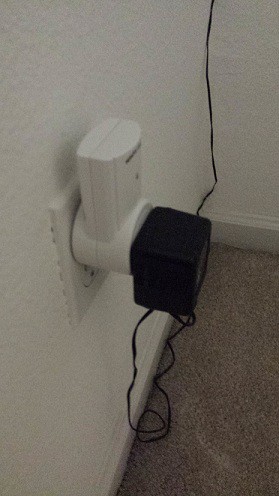
For the end of the base steps: Plug an outlet switch in between each outlet you want to control and whatever you want it to control.
Not that you need a picture, but:
![]()
Congrats! You now have a passable web-based home automation system. Stay tuned for the sci-fi aspect.
-
5Step 5
For each machine where you want speech recognition:
Run the JarvisListBox app, and set it to run at start-up.
If you feel comfortable with code, you can edit its commands in the ListBox constructor to make it more appropriate for your setup.
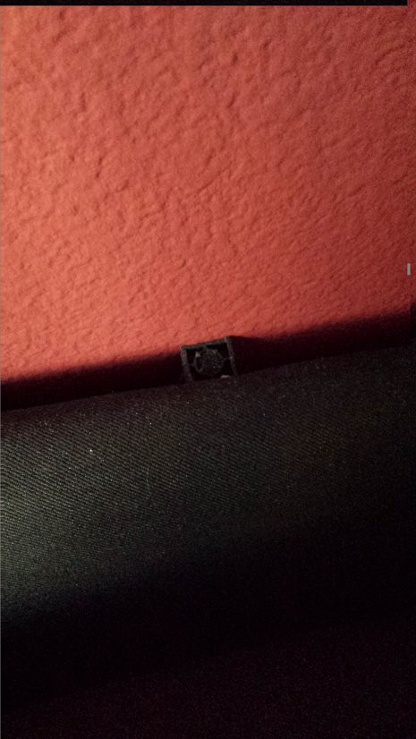
Running microphones around the house will increase its capabilities a lot. I found that each computer could handle 2 microphones spaced about 4 feet apart, and worked from there. I used microphones acquired from AS&S, but their inventory is inconsistent, so YMMV. I hid them behind furniture as shown (with custom wiring, as the microphones I got had a non-standard connector).
![]()
-
6Step 6
For the outlet power detectors:
Cut the connectors off of your two wall warts and solder the grounds together (and to the ground on their Arduino)
Solder the +5v wire of one wall wart to the +5v plug on the Spark core, and the other to digital input 3 (label the first as "Power" and the second as "Control")
Upload the OutletDetector.ino sketch to this one and you should be good to go. To test, plug and unplug the control plug while the power plug is in. You should see the LED (or pin 13) turn on and off as you do this. Depending on your brick, there may be some delay.
You'll need to copy the keys from your Spark.IO account into the DuinoDaemon program for this one to work, but it shouldn't be too much work.
-
7Step 7
For the Androids involved:
This one requires a bit more customization (unless you want a floorplan of my apartment in your system for some reason). You will need to download Unity and adjust the app to your needs. I am not planning on providing complete detail here unless people request it, because the structure of the program should be relatively simple if you're familiar with Unity. As for the art, I will be providing the SVG files in the near future). Otherwise, you could just put a link to the web interface on your home screen.
-
8Step 8
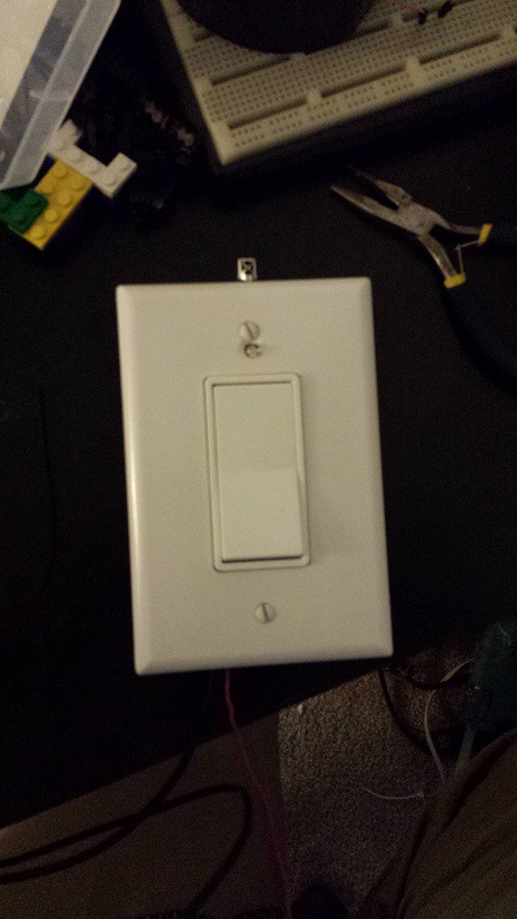
To build the light switches (I'm not using these, but they might work better for those of you who don't rent):
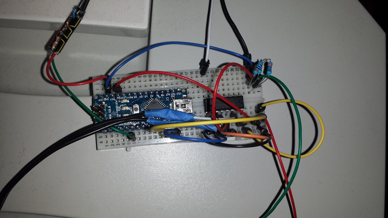
Using the pictues below as guides, solder the relevant wires to the Arduino...
I kid.
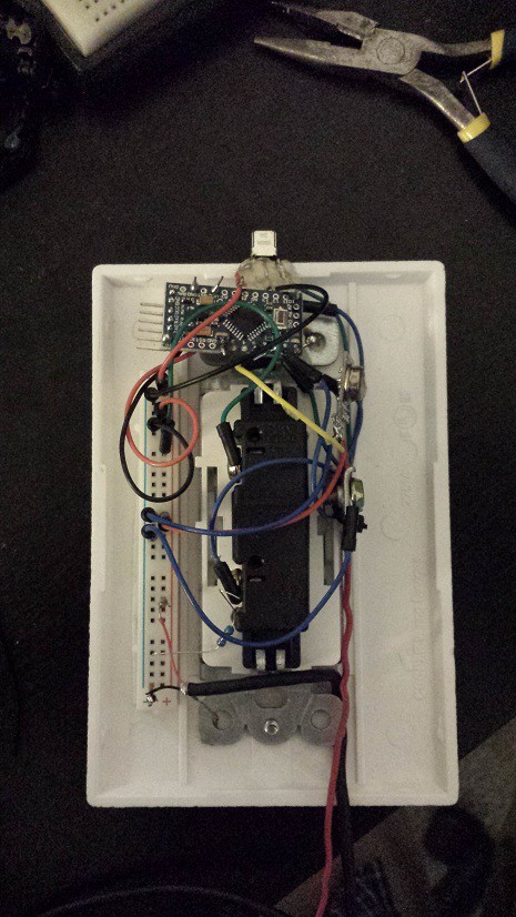
There are a few important parts here: There's the Arduino, the tri-color LED, the IR sensor (only important if you want to use the sonic screwdriver), the RF Transmitter, and the switch itself.
In this case, the pin assignment is actually somewhat important, because this node uses two timers and two PWM outputs, which stretches the poor Arduino Nano to its limits. The switch and IR detector can be put anywhere that isn't used by anything else though. Exact pin locations are on the way.
The other important thing to note here is the wiring of the switch. One side is wired to +5v, the other to the Arduino's input pin and, via a 1Mohm pull-down resistor, to ground. This may be obvious to hardware gurus, but for the rest of us, that stops the analog reading from pulling the switch pin high and throwing off the readings
![]()
![]()
-
9Step 9
Building the blind minder breakout board:
For this one, I think I'm just going to give a picture, a sketch, and the STL files. It's so simple it's not even really worth a full build log.
![]()
Clockwise from the top left, the outbound pairs are:
9V brick (for the blinds)
Motor
LED strip (for the inner glow
IR LED (for TV control)
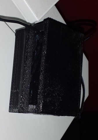
In the case:
![]()
-
10Step 10
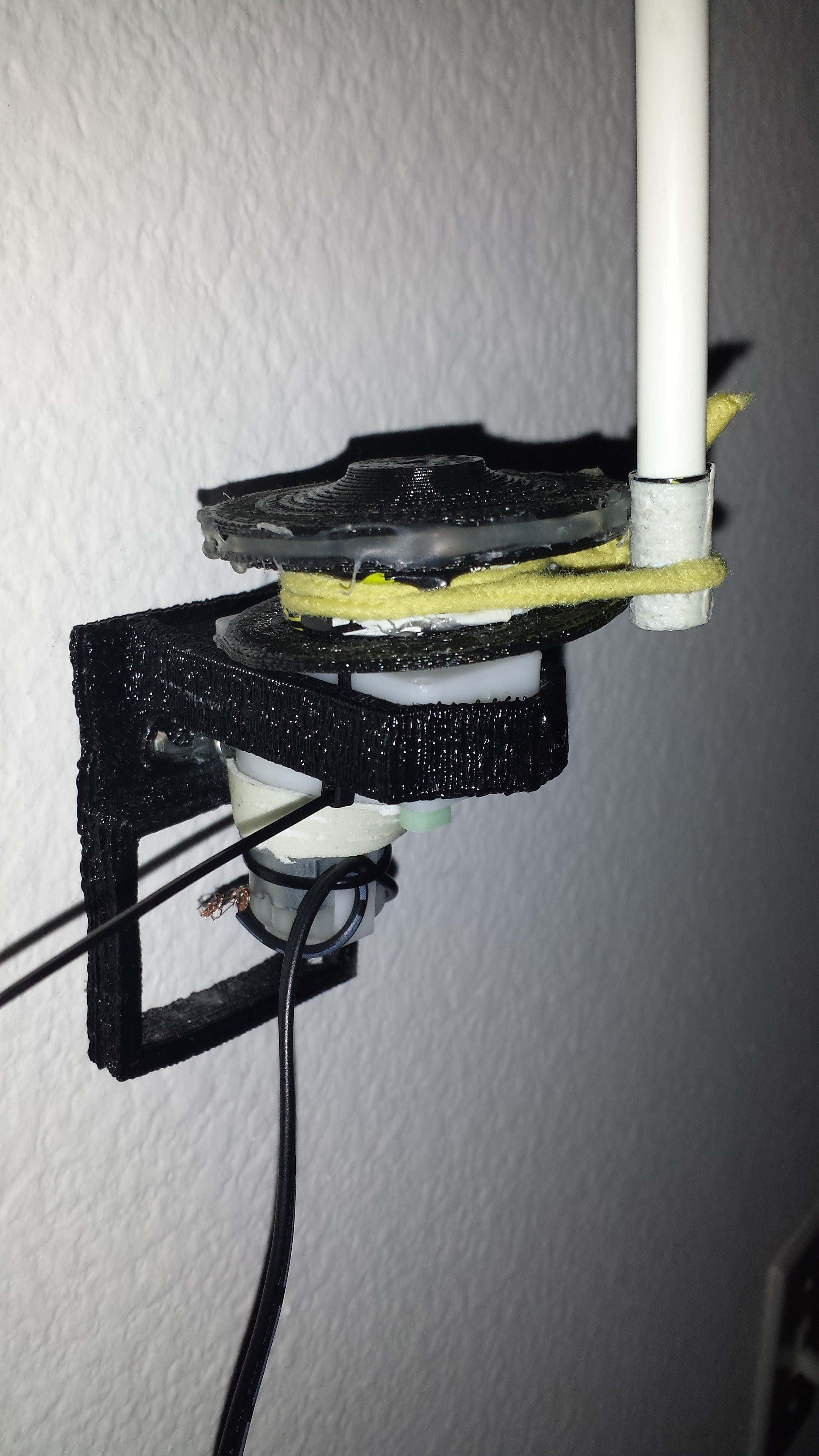
The blind minder itself:
![]()
(STL files in GitHub)
Print the spool
Print the mount
Hot glue the spool directly to the motor shaft
Wrap a piece of duct tape inside-out around the existing stick
Do the same around the inside of the spool
Use your girlfriend's hair tie to band the two together (Important: Don't tell her until afterwards)
Bolt the mount to the wall.
Tape the motor to the mount (Strictly speaking, this could have been avoided with a better mount design, but I was getting lazy, and I still have a game to finish once this is done).
Sci-fi grade Home Automation
A system that ties some home automation with various APIs and hardware hacks.
Discussions
Become a Hackaday.io Member
Create an account to leave a comment. Already have an account? Log In.