-
Brackets for the 'UV Oven'
04/25/2015 at 05:49 • 0 commentsHere's the brackets for the UV Oven Project!
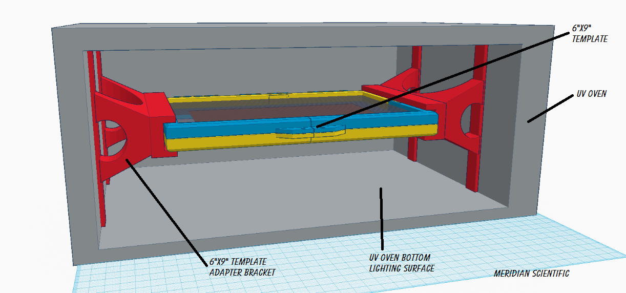
From the front...
![]()
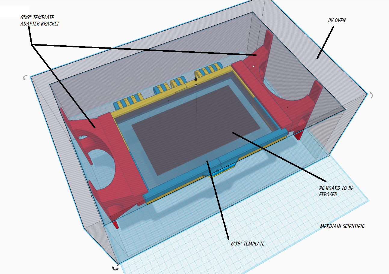
From above...
![]()
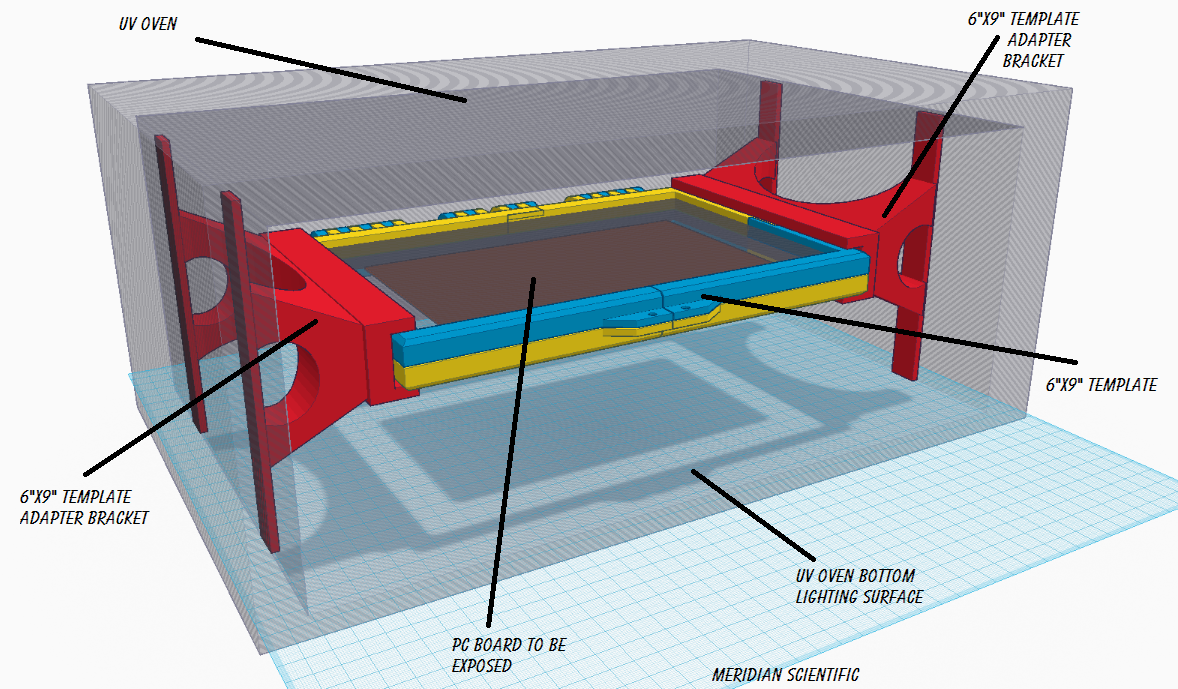
Better front view....
![]()
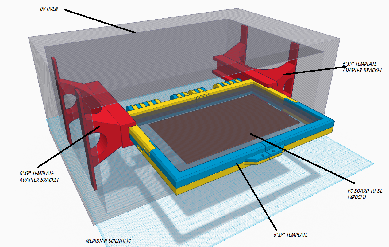
And with the template only half way in....
![]()
And of course, these files are all in the GitHub repo....
-
Files are in the gitHub!
04/24/2015 at 12:19 • 0 commentsThe .stl files for the renderings above are now in the gitHub... I'll obviously be adding to them... But I figured I'd put it out there...
![]()
-
A little better example..
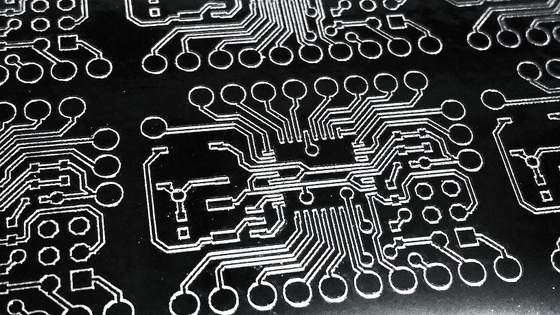
04/24/2015 at 07:56 • 0 commentsThis isn't a negative... but it was tested on glass... But this shows the resolution I'm getting using Chilipeppr now.. I'm quite happy...!
![]()
-
Example
04/11/2015 at 08:10 • 0 commentsSo, this probably should be posted in the other project since this is a positive, not a negative for the glass...but I was testing the parameters... this is on glass, but it's a positive image cut... I just wanted to illustrate the traces...
These are near perfection...
![]()
If you did this on copper instead of the glass like I did here.. this would come out very nice... I'm going to go ahead and try this on copper tomorrow and post it on the other project ( https://hackaday.io/project/3904-tonerless-pcb-etch-resist-direct-to-pcb-method )...
![]()
Getting very close now....
Just need to get chilipeppr to allow layer selection, allow reversing the layer image, and toggle M3 and M5 instead of moving the Z axis...and it'd be awesome...
Anyone wanted to help me fork chilipeppr.com's eagle .brd import to do these things...I'll do just about anything.. =)
-
Small update
04/11/2015 at 07:23 • 0 commentsSo, here's some updated setting I have been using to get better resolution from chilipeppr.... ( this is with my 1watt laser, so the cut speed is pretty high )
Inflate Milling Path By:
	positive +0.05
	negative -0.05

Advanced Inflating
	Inflate SMDs By
		positive checked -0.1
		negative checked -0.1
	Clip wires
		unchecked
	Remove Undefined SMDs
		unchecked
	Inflate Pads By
		checked -0.1
	Inflate Vias By
		unchecked 0

Depth of Milling Traces
	0
Feedrate for Milling Traces
	400
Feedrate for Plunge into Copper
	800
Clearance for Z Axis Moves
	0
Depth of Cutting Out Dimensions
	0
Step Down for Cutting Dimensions
	0
Feedrate for Cutting Dimensions
	400
And here's slightly upgraded python script that lets you use the input and output names as command line arguments.. Pretty basic still...and it still keys off the cut speed, so I need to find a better way...just haven't spent the time yet...
import os import sys total = len(sys.argv) cmdargs = str(sys.argv) inputFile = sys.argv[1] outputFile = sys.argv[2] if os.path.exists(outputFile): os.remove (outputFile) outFile = open(outputFile, 'a') with open(inputFile) as f: for line in f: if line.startswith( 'F400' ): outFile.write("M3" + chr(13) + chr(10)) print ('M3') if line.find( 'G0' ) != -1: outFile.write("M5" + chr(13) + chr(10)) print ('M5') outFile.write(line) print (line) outFile.close() -
A little further...
04/11/2015 at 06:37 • 0 commentsSo, here's some etching into the aluminum I did using the vinyl as a resist layer... I tried various combinations of HCl + H2O2 and ended up going with stragiht HCl ( something like 30% pool variety from home depot )...
Here is a freshly laser cut layer of vinyl on top of the adhesive aluminum....on a test plate of glass....
![]()
Here is the vinyl bits peeled away to expose the aluminum for etching...(remember this is a negative)...
![]()
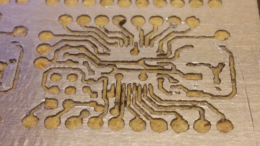
And here it is after etching.... My first try, so it's a little sloppy and undercut...the goop from the vinyl being cut should probably be removed with goo-gone or something before etching...acetone doesn't work well on the vinyl...
![]()
Here's the back... a lot of undercutting...I'll work this out later.. ;)
![]()
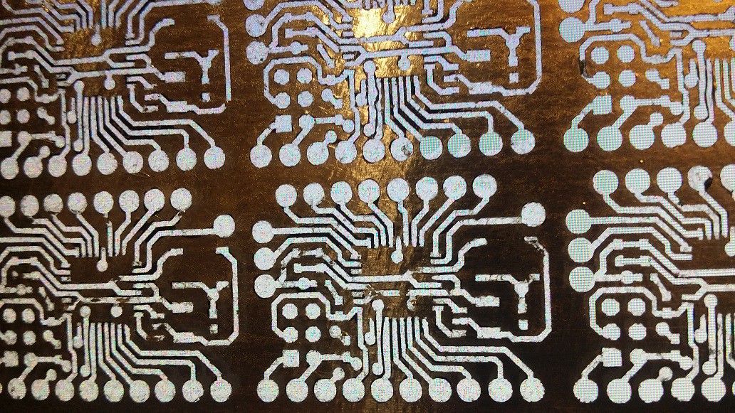
And this is the light from my monitor shining through the glass plate....
![]()
All in all, I think this is a pretty good proof of concept...the resolution on the TQFP32 is pretty good I'd say... Since these pictures have been taken, I refined the settings a little and have managed to make it even better... Keep an eye out!!
-
Experimenting
04/03/2015 at 22:49 • 0 commentsSo, here are some experiments I've done with etching the aluminum negative for the glass plate.... I've converted over 100% to chilipeppr.com since it turns out to be awesome... I've been using the Eagle .brd import feature....with the following settings...
Inflate Milling Path By:
	0

Advanced Inflating
	Inflate SMDs By
		checked -0.12
	Clip wires
		unchecked
	Remove Undefined SMDs
		unchecked
	Inflate Pads By
		checked -0.1
	Inflate Vias By
		unchecked 0

Depth of Milling Traces
	0
Feedrate for Milling Traces
	400
Feedrate for Plunge into Copper
	800

Clearance for Z Axis Moves
	0

Depth of Cutting Out Dimensions
	0
Step Down for Cutting Dimensions
	0
Feedrate for Cutting Dimensions
	400
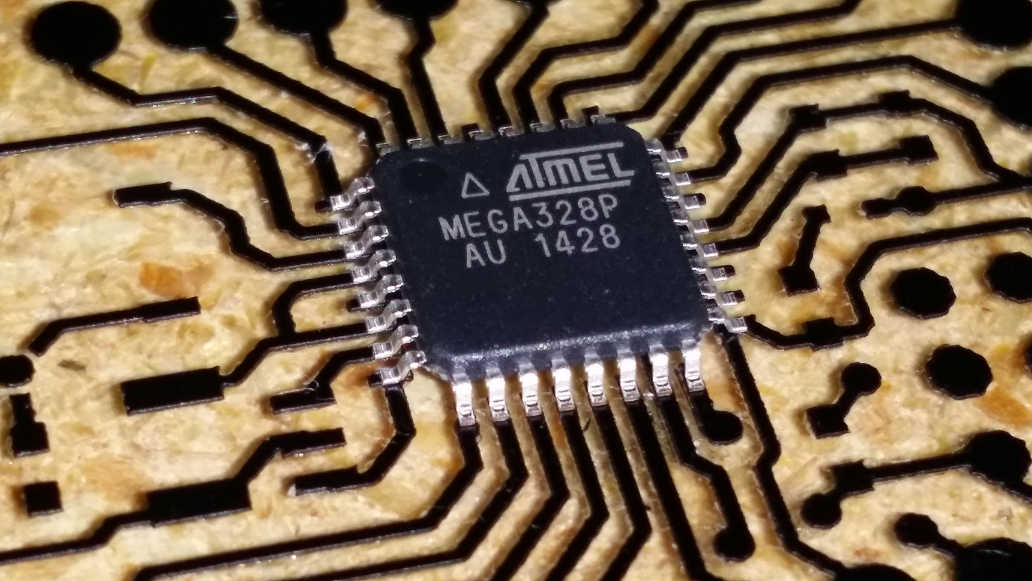
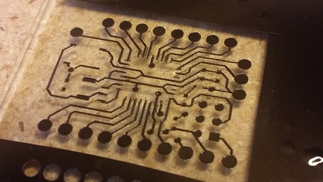
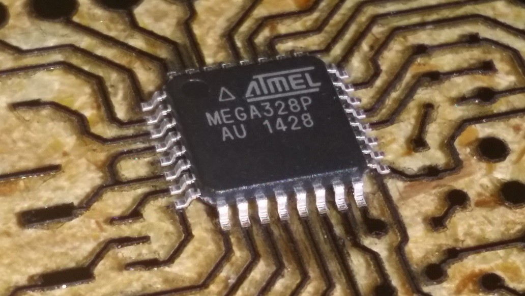
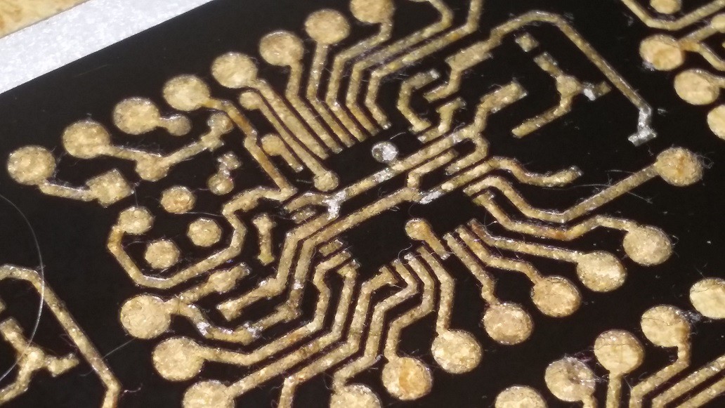
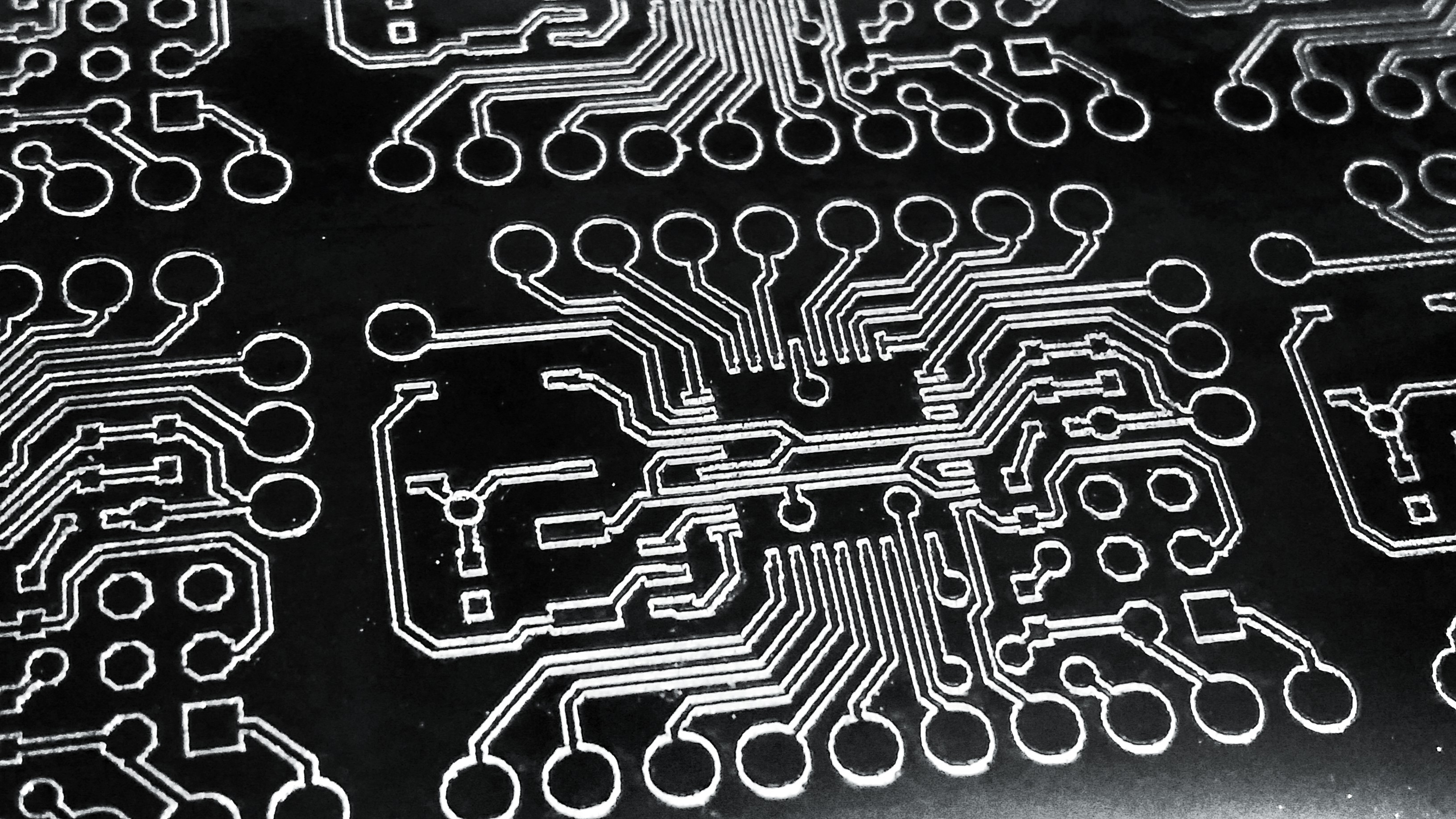
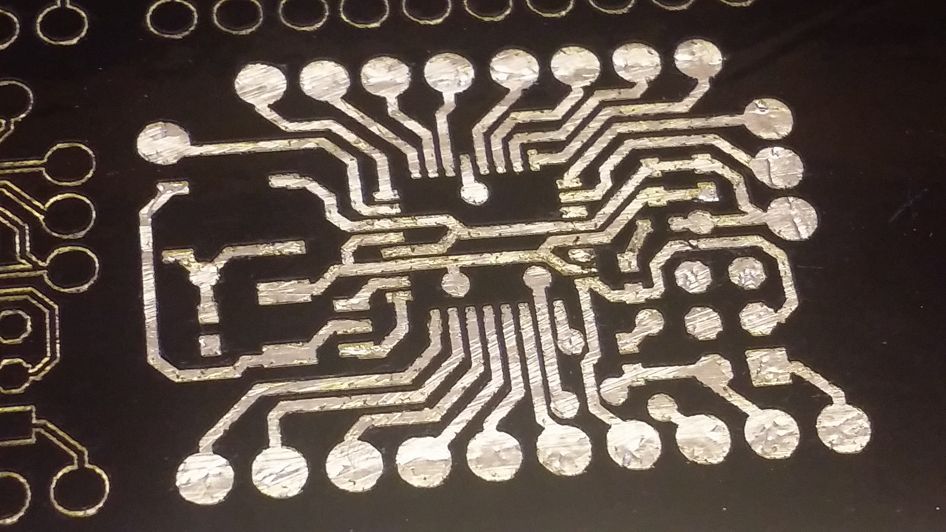
I skip the send gcode to workspace step... copy the gcode from the textbox... I then paste that gcode into a text file...I use a .tap extension... And run a overly simple python script on it to insert my M3 and M5 commands to turn the laser on and off instead of moving the Z Axis.... Here's that code.....it's not great....import os os.remove ('new.tap') outFile = open('new.tap', 'a') with open("mcu_panel.top.etch.tap") as f: for line in f: if line.find( 'Z-' ) != -1: outFile.write("M3" + chr(13) + chr(10)) print ('M3') if line.find( 'Z0' ) != -1: outFile.write("M5" + chr(13) + chr(10)) print ('M5') outFile.write(line) print (line) outFile.close()I then take the new.tap gcode file it creates (I also remove the dimensions section since I haven't added that to the code yet) and drop it back into chilipeppr.... Hopefully this can be streamlined later...but it certainly works for now...This is a TQFP32 for an atMega328.. This is the glass plate with a layer of aluminum tape and a layer of adhesive vinyl on top of that...then cut with a 1w 445nm laser at 400mm/sec... A panel of these goes in about 5-10minutes...
![]()
Here is the same board with the vinyl removed... Take note that this step only has to be done ONCE... After you've done this, then etched the aluminum you'll have a template that can be used indefinitely... Treat it right and you'll never replace it..having used it over and over again...
![]()
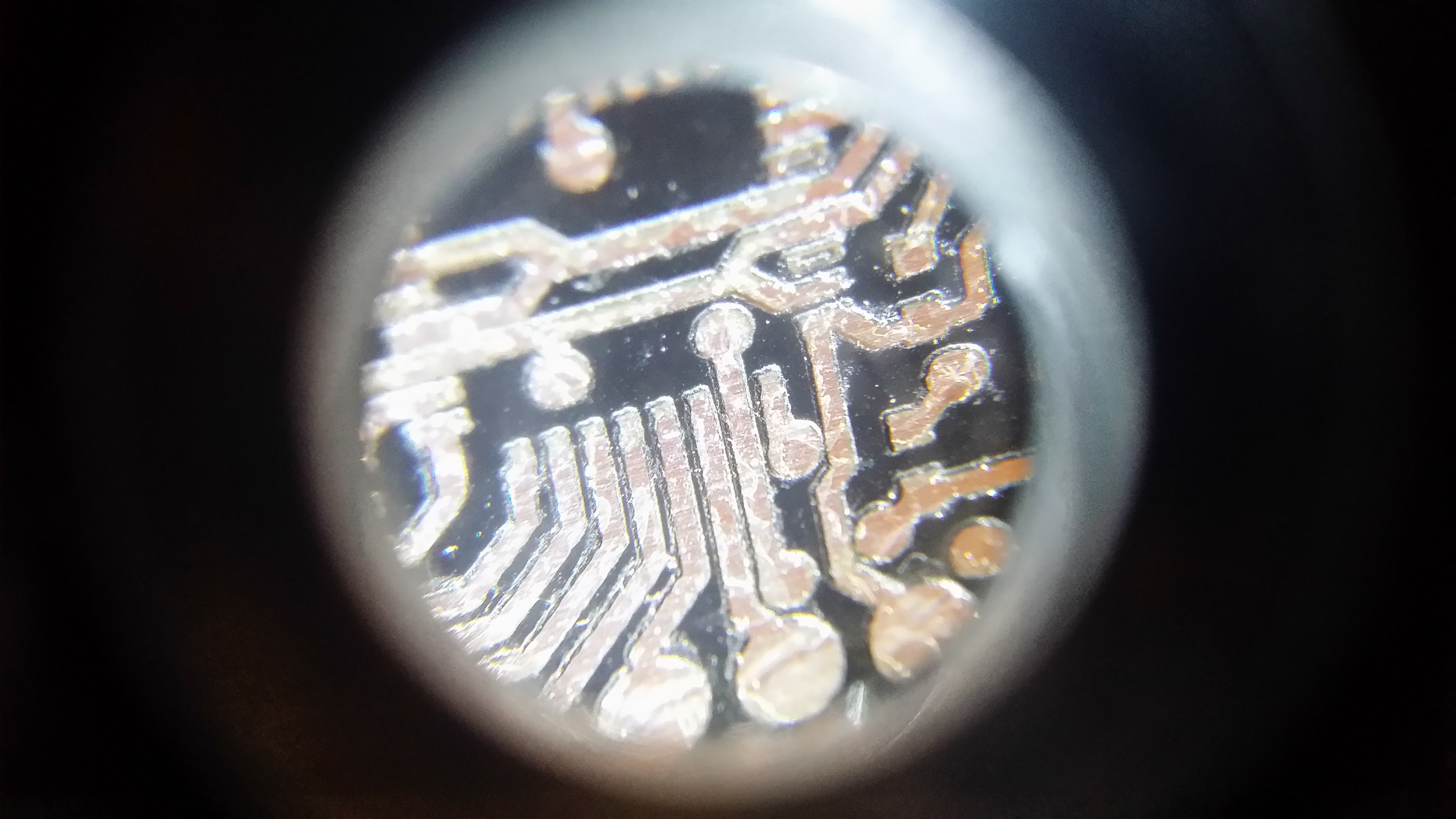
A little closer....
![]()
And there you go for now.. I've started the etching experiments... More on that later, but I am using a HCl + H2O2 mixture... It seems a little weak at a 2 part H2O2 and 1 part HCl... Straight HCl is too aggressive... so I'm trying to find a good balance... with the 2to1 ratio, it worked just a little slow. And keep in mind this will also be an automated process with the desktop etching machine I am designing... yay..
-
Design
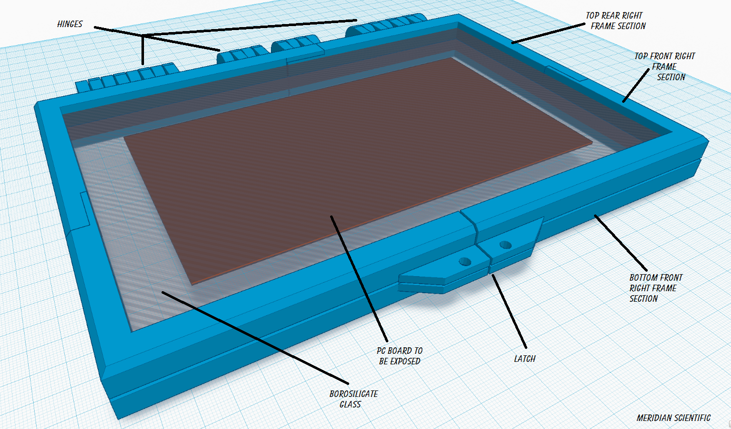
03/21/2015 at 19:46 • 0 commentsSo, I'm starting the design for this now... I want it to be sort of like a book where the PCB fits into an area outlined with the gasket material and the glass presses down and forms a tight fit with the PCB in the center...then clamps down.. then the whole thing slides into the 'UV OVen' and gets exposed.. two sides at once.. and if your board is small enough, you can expose several at once.. I'll keep updating the renderings as I get it going.. The frame will be 3D printed, but may have to be either coated in aluminum foil or something to keep the UV from attacking the plastic... I want these to last a long time....through many exposures..
Tonerless PCB Templates for UV Exposure
A method for creating long life reusable templates for UV exposing PC Boards
 fl@C@
fl@C@