-
An even better idea - Mute circuit
01/15/2019 at 06:25 • 0 commentsThe design files are available in the files section.
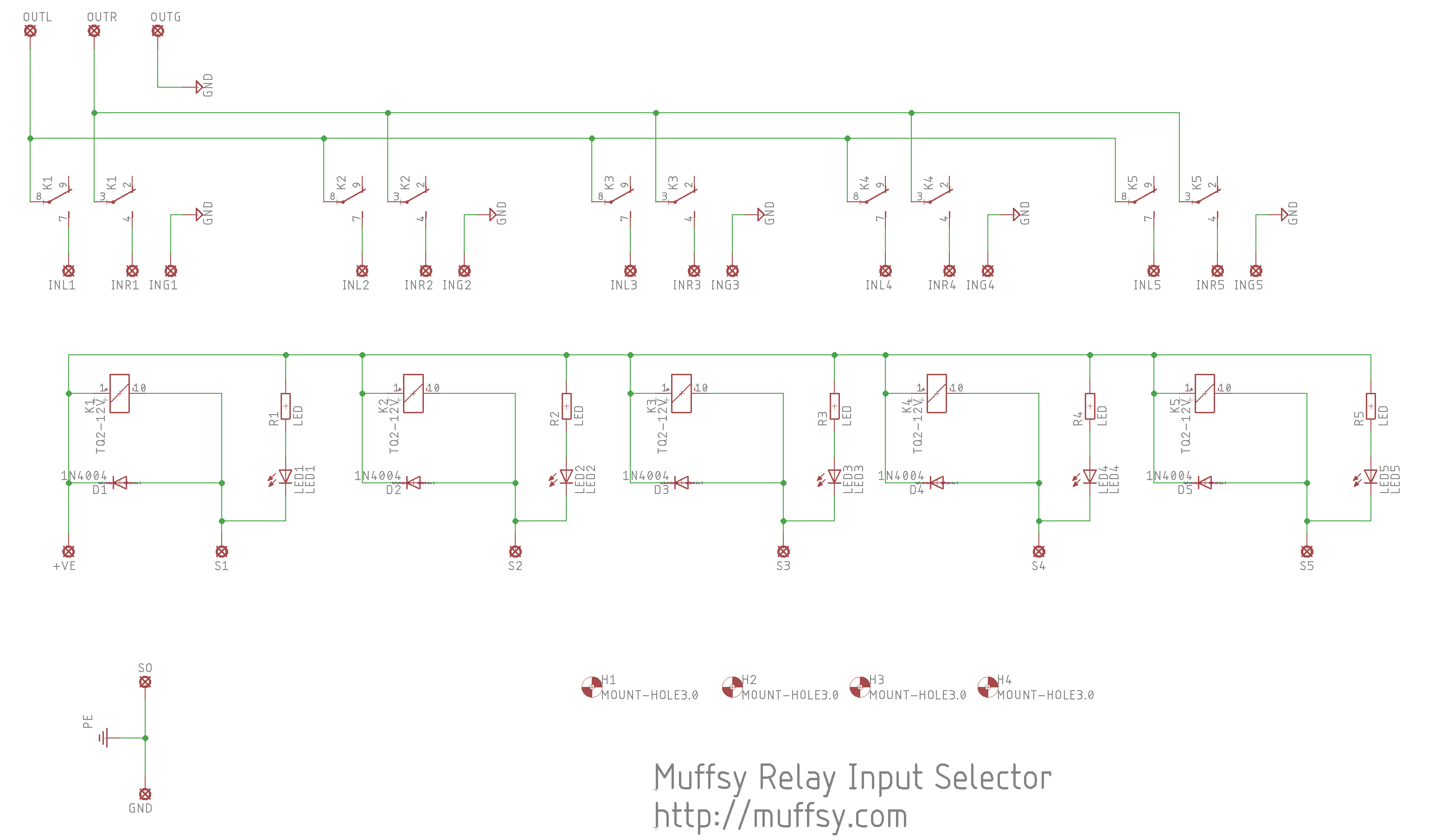
To avoid pops when turning the preamp circuitry on and off, a mute circuit is really useful. So I sacrificed one input and converted the fifth relay to mute.
The functionality of this board is now:
- Four inputs, one input, one mute relay
- All relays (except the SSR control, which technically isn't a relay) have flyback diodes to prevent clicks and pops
- The relays (TQ2-5V) are "make before break", which also prevents clicks and pops when changing to another input
- Separate power and signal GND
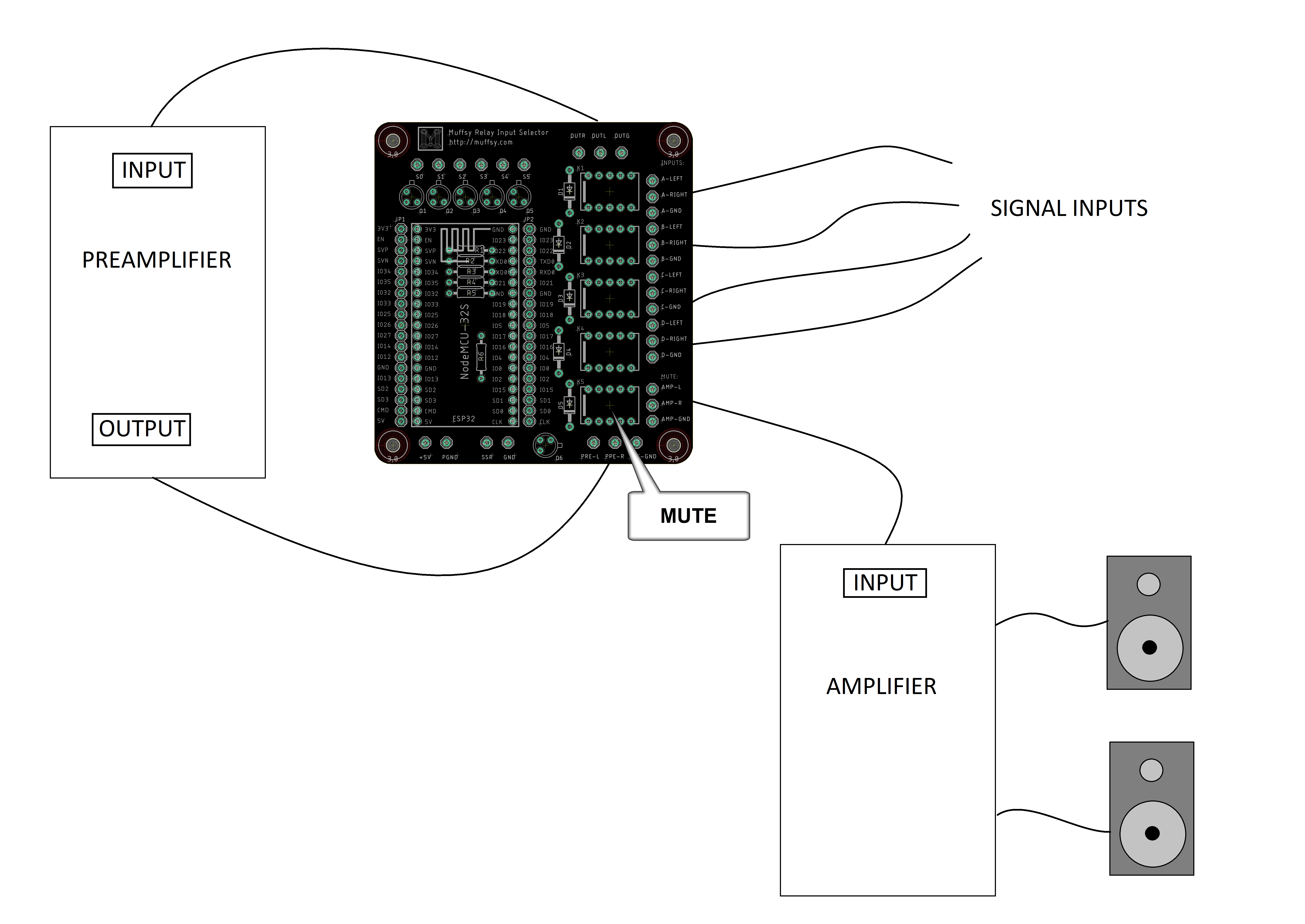
- Mute, goes between the preamp output and the power amp input.
- Control for Solid State Relay (SSR)
- Break-out for all ESP32 pins (even those that are in use for relays)
- Control inputs with rotational switch
or - Control inputs, SSR and mute with ESP32
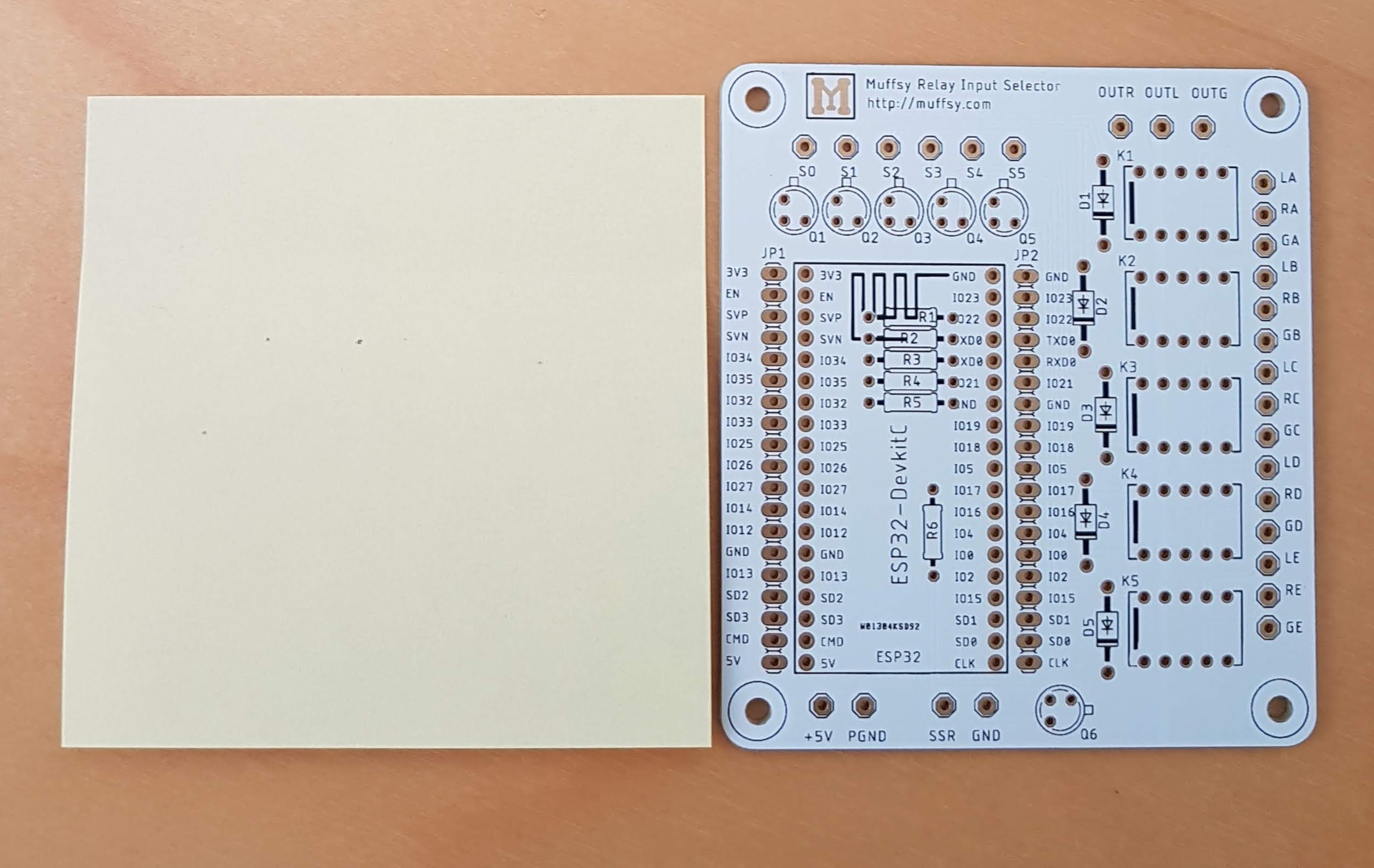
Here's a quick and dirty drawing in MS Paint to show what I mean:
![]()
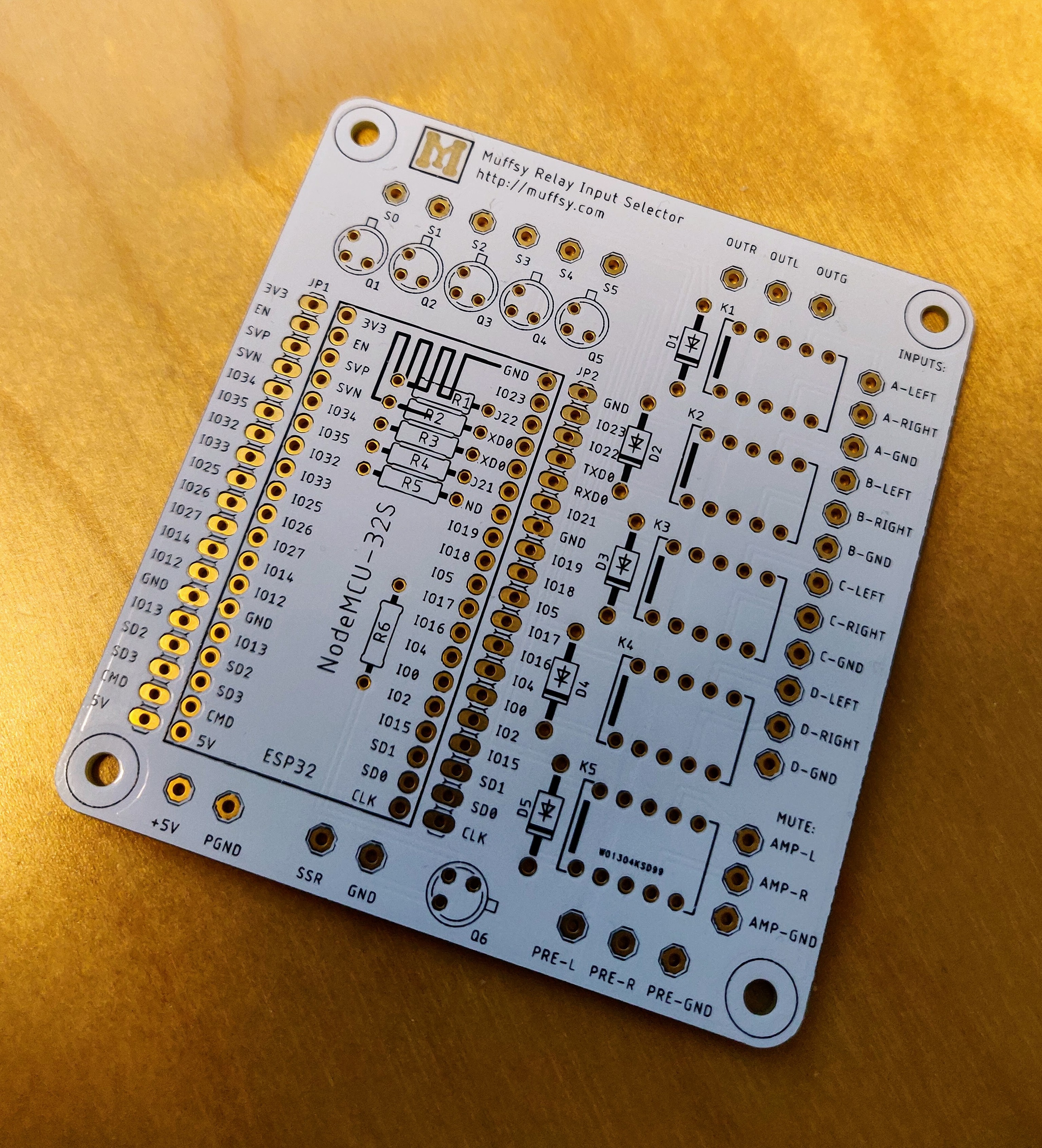
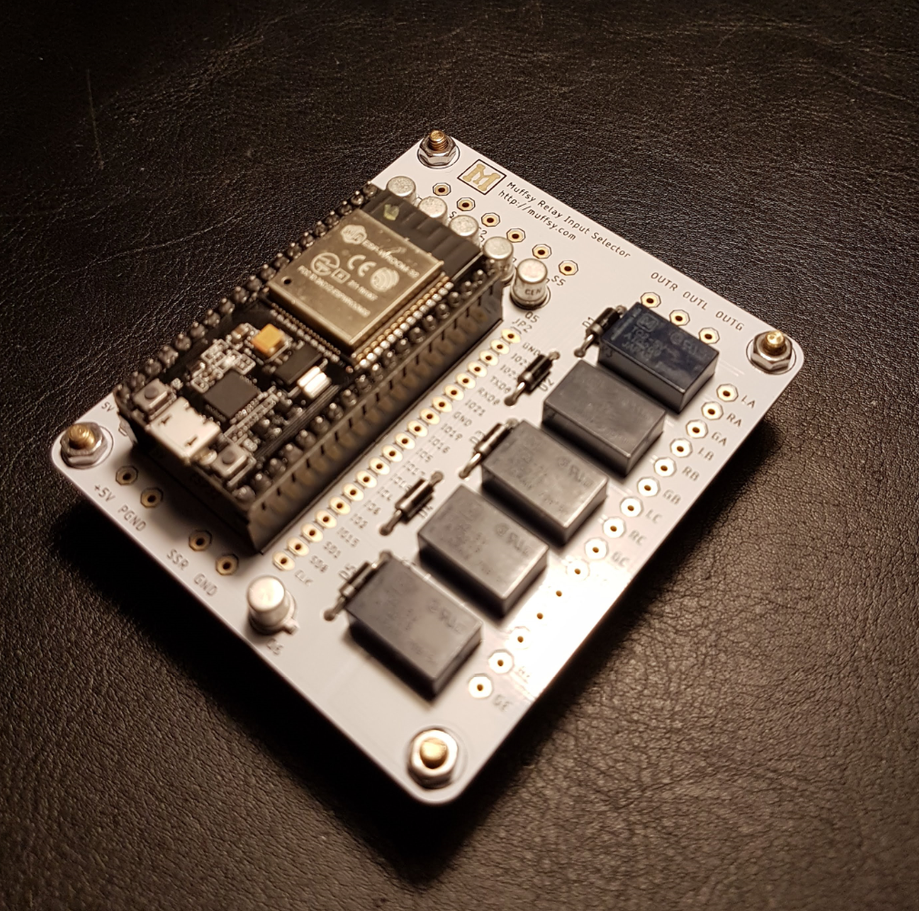
Picture of the actual board:
![]()
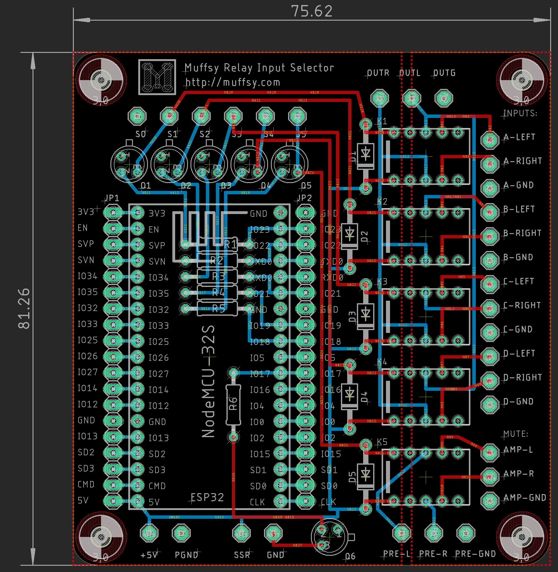
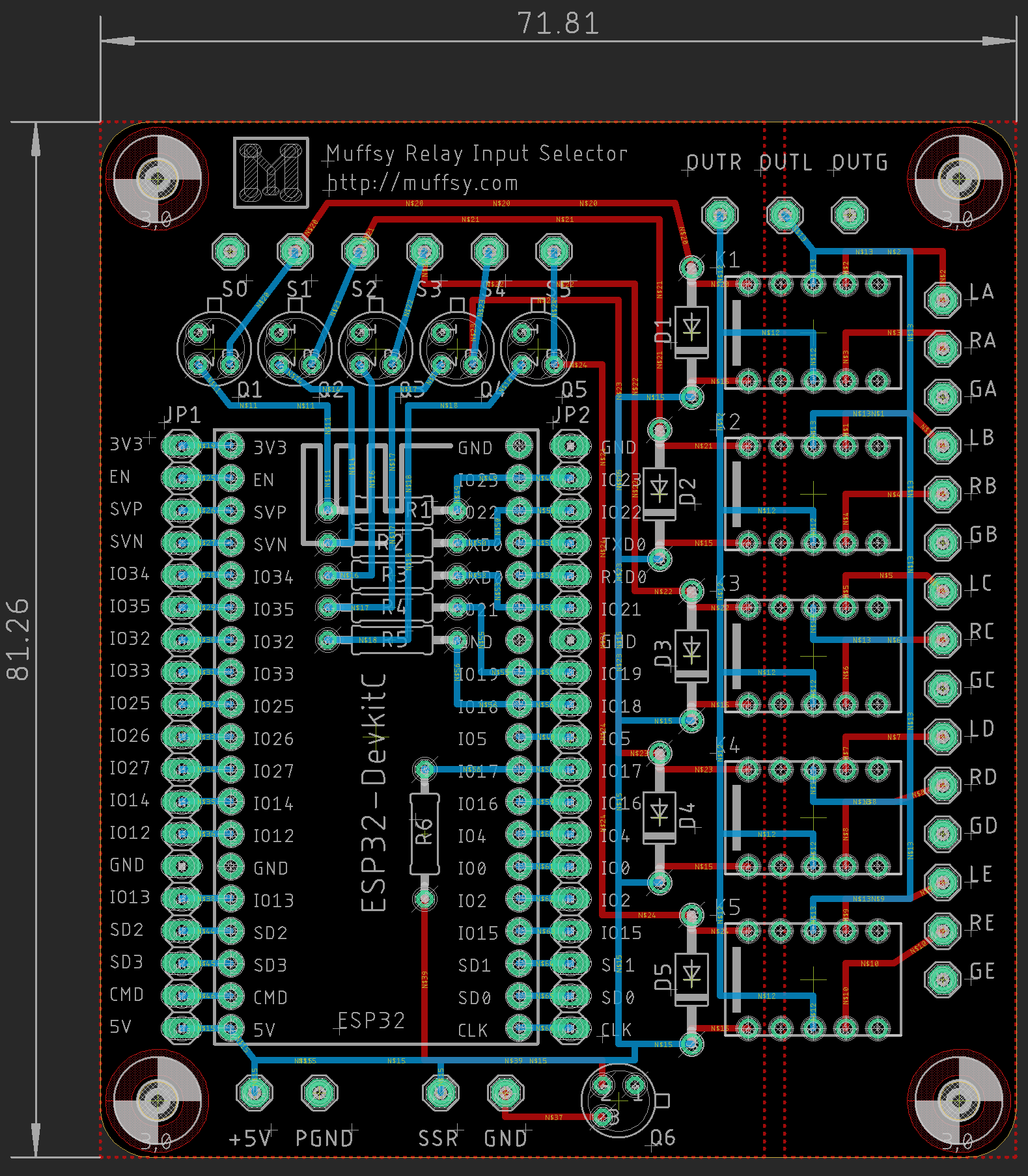
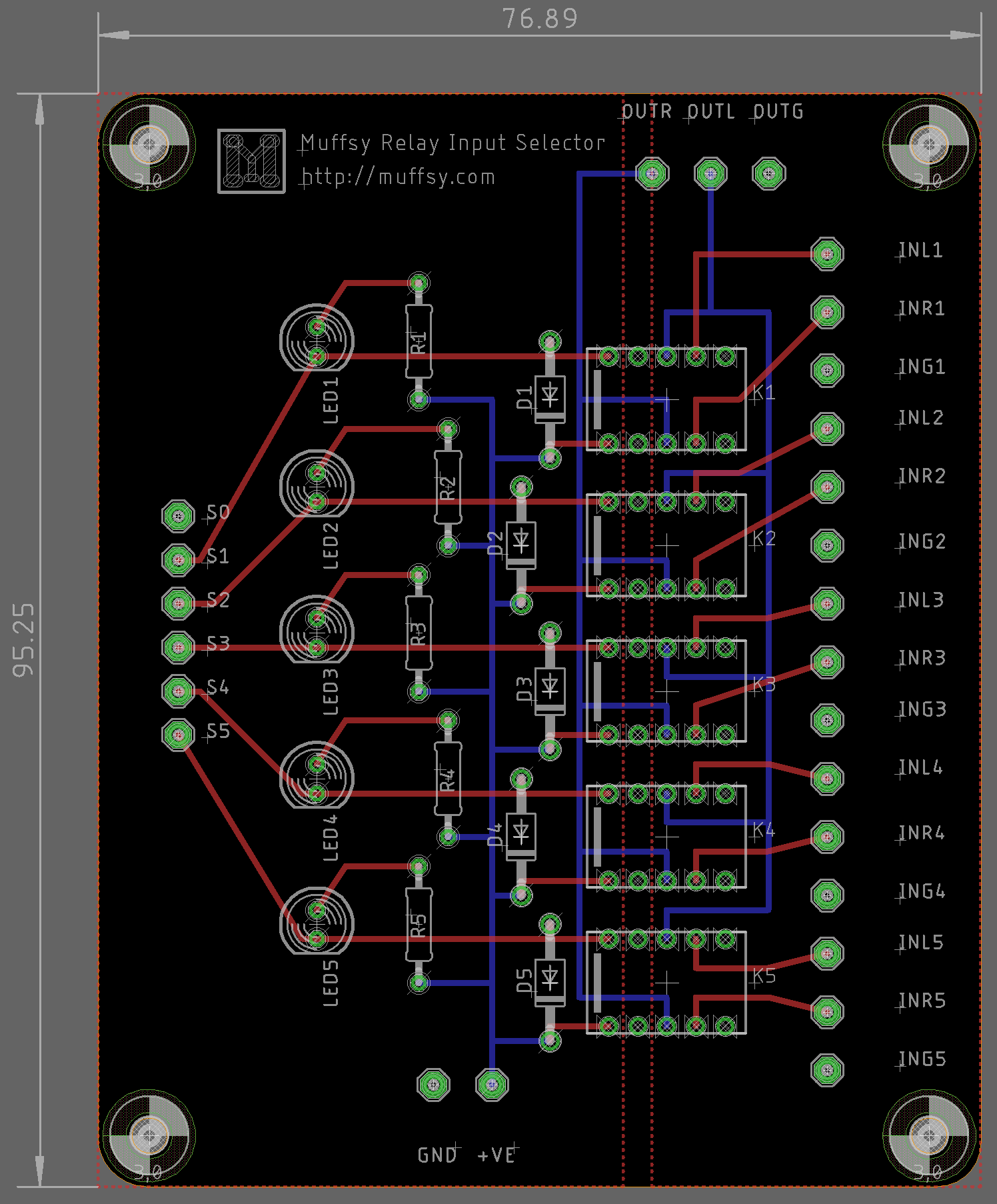
Below is the design in Eagle, the big red rectangles are the two separate ground planes. A Post-IT note is 76x76 mm by the way.
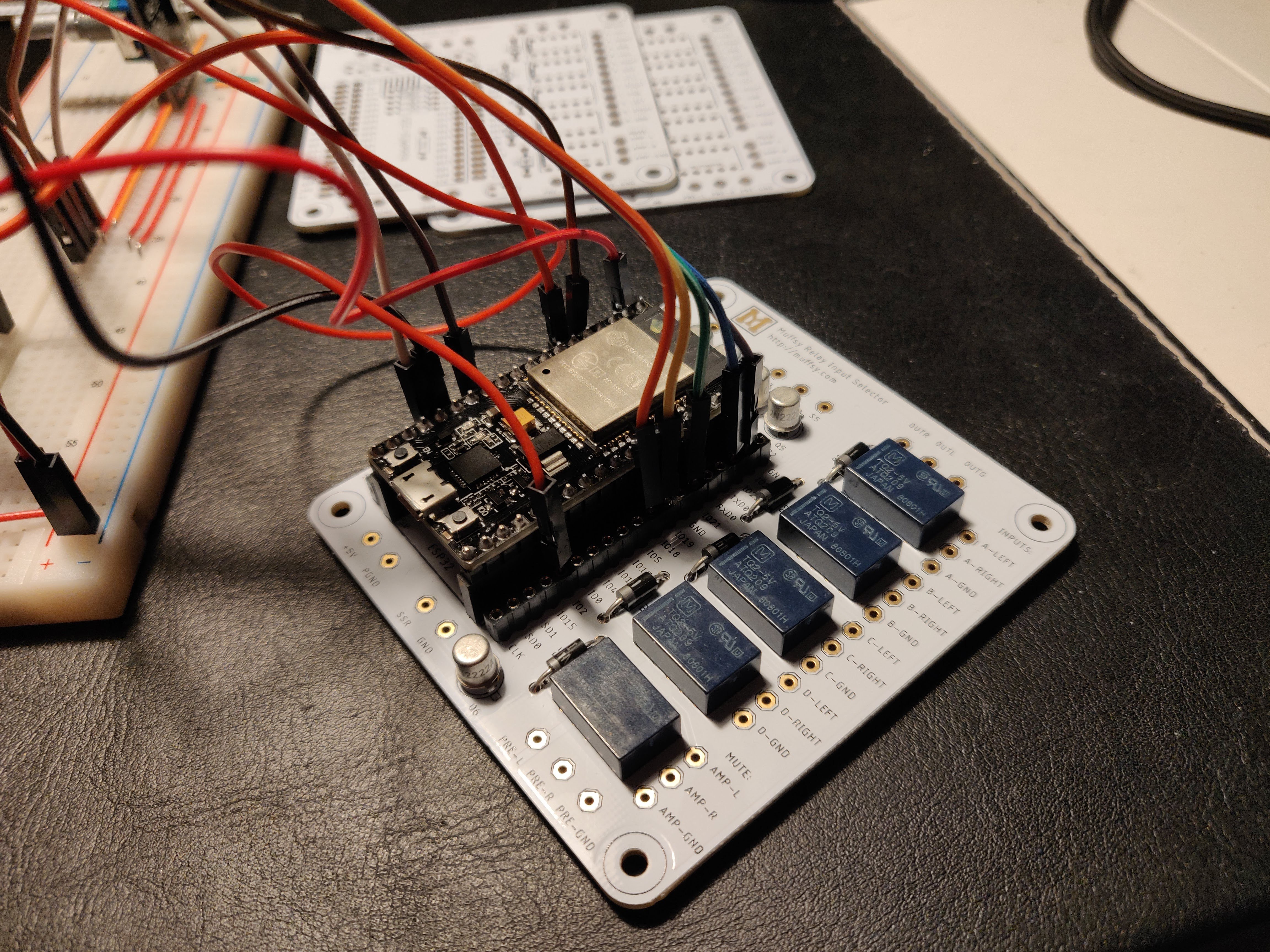
Here's the final build.
![]()
Arduino Code, Four Inputs and Mute
/* Muffsy Relay Input Selector * * Control relays using IR and rotary encoder * Control external power to amp using IR and push button * */ /* * powerState: * * 0: Boot * powerOn() * startup procedure * read NVRAM (relayCount) * set relays to off (previousRelay = relayCount) * set power amp to off, SSR = LOW * * 1: Powered ON * turn on power button LED * set power amp to on, SSR = HIGH * trigger relayOn(): previousRelay = relayCount + 1 * rotaryEncoder() * increases or decreases relayCount depending on rotational direction * pushbutton: Power ON/OFF * does only Power ON if powerState == 2 * irRemote() * input up/down * input direct (buttons 1-5) * power on/off * does only Power ON if powerState == 2 * relayOn() * activates relays based on the relayCount * handles relayCount too high or low * powerControl() * read power button, set powerState accordingly * * 2: Powered OFF * turn off all relays * set power amp to off (SSR = LOW) * powerControl() * read power button, set powerState == 1 if pushed * irRemote() * read power button, set powerState == 1 if pushed */ // Libraries #include <IRremote.h> // IR Remote Library #include <EEPROM.h> // EEPROM Library // Size: 1 (relayCount) #define EEPROM_SIZE 1 // Variables, pin definitions // Onboard LED/Power LED #define LED 2 // IR Receiver pin and setup #define IR_Recv 13 IRrecv irrecv(IR_Recv); decode_results results; // Power button #define poweronButton 14 // Pins for the rotary encoder: #define rotaryA 35 #define rotaryB 34 // Relays #define R1 23 #define R2 22 #define R3 21 #define R4 19 #define R5 18 //Solid State Relay #define SSR 17 // Rotary Encoder variables int counter = 0; int previous = 0; int aState; int aPreviousState; // Relay Array int relays[] = {23, 22, 21, 19, 18}; // Relay variables int relayCount; int previousRelay; int relayNumber; // Power/Mute variables int powerState; int buttonState = 1; // the current reading from the input pin int lastButtonState = 1; // the previous reading from the input pin unsigned long lastDebounceTime = 0; // the last time the output pin was toggled unsigned long debounceDelay = 50; // the debounce time; increase if the output flickers int mute = 0; // Mute on/off (1/0) // Setup void setup() { // Power button pinMode (poweronButton,INPUT_PULLUP); // Onboard LED pinMode (LED,OUTPUT); // Rotary Encoder pinMode (rotaryA,INPUT); pinMode (rotaryB,INPUT); // Reads the initial state of the rotaryA aPreviousState = digitalRead(rotaryA); // Relays pinMode (R1,OUTPUT); pinMode (R2,OUTPUT); pinMode (R3,OUTPUT); pinMode (R4,OUTPUT); pinMode (R5,OUTPUT); pinMode (SSR,OUTPUT); // Relay variables EEPROM.begin(EEPROM_SIZE); relayCount = EEPROM.read(0); previousRelay = relayCount + 1; // Start out not matching relayCount??? // Start the IR Receiver //pinMode(IR_Recv, INPUT_PULLDOWN); irrecv.enableIRIn(true); // Starts the receiver /* * powerStates: * 0: Powering on * 1: Powered on * 2: Powered off */ powerState = 0; mute = 0; // Mute on/off (1/0) // Serial monitor Serial.begin (115200); } /* * Main program */ void loop() { if (powerState == 0) { powerOn(); } else if (powerState == 1){ relayOn(); rotaryEncoder(); // Include Push = MUTE powerControl(); // Read power button irRemote(); // Up, Down, Direct, Volume, MUTE, Power } else { rotaryEncoder(); // Rotary push button is temporarily power button??? powerControl(); // Read power button irRemote(); // Power on/off only } } /* * Turn on current relay */ void relayOn() { // If relayCount has changed: Turn on the selected relay (next, previous, direct) // If previousRelay has changed: Turn on the last selected relay if (relayCount != previousRelay) { // Rollover 3 or 0 if (relayCount > 3) { relayCount = 0; } else if (relayCount < 0) { relayCount = 3; } // Turn off all relays, then turn on relayCount relayOff(); digitalWrite(relays[relayCount], HIGH); // Stop IR, write relayCount to memory, start IR irrecv.enableIRIn(false); EEPROM.write(0,relayCount); EEPROM.commit(); irrecv.enableIRIn(true); Serial.print("[http://muffsy.com]: Written \"relayCount = "); Serial.print(relayCount); Serial.println("\" to save slot 0"); // Reset counters, output relayNumber previousRelay = relayCount; relayNumber = relayCount + 1; Serial.print("[http://muffsy.com]: Activated relay #"); Serial.println(relayNumber); Serial.println(); // If circuit is muted, unmute if (mute == 1) { Serial.println("[http://muffsy.com]: Waiting 1.5 seconds before turning off mute"); delay(1500); toggleMute(); } } } /* * Power on amplifier */ void powerOn() { // Only called if powerState is 0 (Powering on) Serial.println("\n --- http://muffsy.com ---\n"); Serial.println("The Muffsy Relay Input Selector has woken up!\n"); Serial.print(" ** Reading saved relay state from NVRAM: "); Serial.println(relayCount); digitalWrite(relays[4],LOW); mute = 1; Serial.println("\n ** Mute Relay turned ON"); Serial.println(" ** All input relays are turned OFF"); relayOff(); Serial.println(" ** Solid State Relay is turned OFF\n"); digitalWrite (SSR,LOW); Serial.println(" ** Startup completed - waiting for Power ON\n"); Serial.println(" -------------------------\n"); // Set powerState to 2 (Powered off): powerState = 2; } /* * Read powerbutton, turn on or off */ void toggleMute() { if (mute == 0) { Serial.println("[http://muffsy.com]: Mute relay turned ON\n"); digitalWrite(relays[4],LOW); mute = 1; } else { Serial.println("[http://muffsy.com]: Mute relay turned OFF\n"); digitalWrite(relays[4],HIGH); mute = 0; } } /* * Read powerbutton, turn on or off */ void powerControl() { int reading = digitalRead(poweronButton); if (reading != lastButtonState) { lastDebounceTime = millis(); } if ((millis() - lastDebounceTime) > debounceDelay) { // whatever the reading is at, it's been there for longer than the debounce // delay, so take it as the actual current state: // if the button state has changed: if (reading != buttonState) { buttonState = reading; // only toggle the LED if the new button state is HIGH if (buttonState == 1) { Serial.println("[http://muffsy.com]: Power button pushed"); if (powerState == 1) { // Turning power OFF: All relays OFF, power amp OFF powerState = 2; digitalWrite (SSR,LOW); digitalWrite (LED,LOW); relayOff(); if (mute == 0) { toggleMute(); } Serial.println("[http://muffsy.com]: Solid State Relay OFF"); Serial.println("[http://muffsy.com]: Power OFF\n"); } else if (powerState == 2) { // Turning power ON: Last selected relay ON, power amp ON powerState = 1; digitalWrite (SSR,HIGH); digitalWrite (LED,HIGH); previousRelay = relayCount + 1; // Trigger relayOn() Serial.println("[http://muffsy.com]: Power ON"); Serial.println("[http://muffsy.com]: Solid State Relay ON\n"); } } } } lastButtonState = reading; } /* * IR Remote */ void irRemote() { // Start irRemote function // Decode the infrared input // Decodes the infrared input if (irrecv.decode(&results)) { long int decCode = results.value; Serial.print("[http://muffsy.com]: Received IR code: "); Serial.print(decCode); Serial.println(); // Switch case to use the selected remote control button switch (results.value) { // Start switch/case case 7770223: // Relay 1 { Serial.println("[http://muffsy.com]: Button \"1\""); if (powerState == 1) { relayCount = 0; } else { Serial.println("[http://muffsy.com]: Powered off, doing nothing...\n"); } break; } case 7774303: // Relay 2 { Serial.println("[http://muffsy.com]: Button \"2\""); if (powerState == 1) { relayCount = 1; } else { Serial.println("[http://muffsy.com]: Powered off, doing nothing...\n"); } break; } case 7766143: // Relay 3 { Serial.println("[http://muffsy.com]: Button \"3\""); if (powerState == 1) { relayCount = 2; } else { Serial.println("[http://muffsy.com]: Powered off, doing nothing...\n"); } break; } case 7787053: // Relay 4 { Serial.println("[http://muffsy.com]: Button \"4\""); if (powerState == 1) { relayCount = 3; } else { Serial.println("[http://muffsy.com]: Powered off, doing nothing...\n"); } break; } case 7748293: // Mute { Serial.println("[http://muffsy.com]: Button \"Mute\""); if (powerState == 1) { toggleMute(); } else { Serial.println("[http://muffsy.com]: Powered off, doing nothing...\n"); } break; } case 7742173: // Channel UP { Serial.println("[http://muffsy.com]: Button \"UP\""); if (powerState == 1) { relayCount++; } else { Serial.println("[http://muffsy.com]: Powered off, doing nothing...\n"); } break; } case 7738093: // Channel DOWN { Serial.println("[http://muffsy.com]: Button \"DOWN\""); if (powerState == 1) { relayCount--; } else { Serial.println("[http://muffsy.com]: Powered off, doing nothing...\n"); }; break; } case 7745743: // Power button { Serial.println("[http://muffsy.com]: Button \"POWER\""); if (powerState == 1) { powerState = 2; digitalWrite (SSR,LOW); digitalWrite (LED,LOW); relayOff(); if (mute == 0) { toggleMute(); } Serial.println("[http://muffsy.com]: Solid State Relay OFF"); Serial.println("[http://muffsy.com]: Power OFF\n"); } else { powerState = 1; digitalWrite (SSR,HIGH); digitalWrite (LED,HIGH); previousRelay = relayCount + 1; // Trigger relayOn() Serial.println("[http://muffsy.com]: Power ON"); Serial.println("[http://muffsy.com]: Solid State Relay ON\n"); } break; } default: { Serial.println("[http://muffsy.com]: Going back to waiting for IR remote keypress\n"); } } // End switch/case irrecv.resume(); // Receives the next value from the button you press } } // End irRemote function /* * Mute (turn off all relays) */ void relayOff() { for (int off = 0; off <= 3; off++) { digitalWrite(relays[off], LOW); } } /* * Rotary Encoder Control of Relays */ void rotaryEncoder() { aState = digitalRead(rotaryA); // Reads the "current" state of the rotaryA // If the previous and the current state of the rotaryA are different, that means a Pulse has occured if (aState != aPreviousState){ // If the rotaryB state is different to the rotaryA state, that means the encoder is rotating clockwise if (digitalRead(rotaryB) != aState) { counter ++; } else { counter --; } } // What to do if rotating Right of Left if (previous != counter) { if (counter > 1) { // Since the encoder gives two signals when turning Serial.print("[http://muffsy.com]: Rotational encoder turned "); Serial.println("clockwise"); if (powerState == 1) { // Increase relayCount relayCount++; } else { Serial.println("[http://muffsy.com]: Powered off, doing nothing...\n"); // Powered off??? } } else if (counter < -1) { // Since the encoder gives two signals when turning Serial.print("[http://muffsy.com]: Rotational encoder turned "); Serial.println("counter-clockwise"); if (powerState == 1) { // Increase relayCount relayCount--; } else { Serial.println("[http://muffsy.com]: Powered off, doing nothing...\n"); // Powered off??? } } } // Reset counters previous = counter; if (counter < -1) { counter = 0; previous = 0; } else if (counter > 1){ counter = 0; previous = 0; } // Updates the previous state of the rotaryA with the current state aPreviousState = aState; } -
Full Functionality - Rotational Encoder and Remote Control
12/06/2018 at 23:36 • 1 commentHere's my test setup:
More about this below. But first, getting there was not all that easy:
IRremote.h and the ESP32
IRremote.h does not want to play nice with ANY library saving anything to the NVS memory. That's sort of a letdown if you'd like to use an infrared remote AND save preferences or states to the ESP32's internal storage.
Here's what happens (continuously, like every 0.2 of a second), showing only one instance of the error:
ets Jun  8 2016 00:22:57

rst:0x3 (SW_RESET),boot:0x13 (SPI_FAST_FLASH_BOOT)
configsip: 0, SPIWP:0xee
clk_drv:0x00,q_drv:0x00,d_drv:0x00,cs0_drv:0x00,hd_drv:0x00,wp_drv:0x00
mode:DIO, clock div:1
load:0x3fff0018,len:4
load:0x3fff001c,len:808
load:0x40078000,len:6084
load:0x40080000,len:6696
entry 0x400802e4
Guru Meditation Error: Core  1 panic'ed (Cache disabled but cached memory region accessed)
Core 1 register dump:
PC      : 0x400d0d78  PS      : 0x00060034  A0      : 0x40081664  A1      : 0x3ffc0be0
A2      : 0x00000001  A3      : 0x00000002  A4      : 0x000000ff  A5      : 0x40086d14
A6      : 0xf0000040  A7      : 0x00290000  A8      : 0x80081188  A9      : 0x3ff5f024
A10     : 0x3ffc1044  A11     : 0x20000000  A12     : 0x00000400  A13     : 0x3ffb1e60
A14     : 0x00000020  A15     : 0xffffffff  SAR     : 0x00000015  EXCCAUSE: 0x00000007
EXCVADDR: 0x00000000  LBEG    : 0x400012e5  LEND    : 0x40001309  LCOUNT  : 0x800d3245
Core 1 was running in ISR context:
EPC1    : 0x4008a377  EPC2    : 0x00000000  EPC3    : 0x00000000  EPC4    : 0x400d0d78

Backtrace: 0x400d0d78:0x3ffc0be0 0x40081661:0x3ffc0c00 0x4008a374:0x00000000

Rebooting...
I tried using EEPROM.h and Preferences.h. It still behaves the same, so I guess the problem must lie with IRremote.h.
The Solution
Sure enough, here's somebody who's encountered the same problem. Not only that, he's also solved it:
https://github.com/espressif/arduino-esp32/issues/928
His solution lets you turn off the IR Receiver when you do an EEPROM.commit, and turn it on again afterwards.
A small problem though, the instructions were a little off. Here's how to make IRremote.h work on the ESP32:
Change the File IRremote.h
On Windows, you'll find the file in Documents\Arduino\Libraries\IRremote\IRremote.h. Search for the following line:
void enableIRIn ( ) ;Replace it with:
void enableIRIn (bool enable) ;Don't forget to do the changes described here as well:
At the end of the file IRremote.h, find this piece of code:
#else
const int sendPin = SEND_PIN;
#endif
} ;
Replace the first line (#else) with:
#elif defined(SEND_PIN)Replace the File esp32.cpp
On Windows, you'll find the file in Documents\Arduino\Libraries\IRremote\esp32.cpp. Replace everything in the file with this code:
#ifdef ESP32

// This file contains functions specific to the ESP32.

#include "IRremote.h"
#include "IRremoteInt.h"

// "Idiot check"
#ifdef USE_DEFAULT_ENABLE_IR_IN
#error Must undef USE_DEFAULT_ENABLE_IR_IN
#endif

hw_timer_t *timer;
void IRTimer(); // defined in IRremote.cpp, masqueraded as ISR(TIMER_INTR_NAME)

//+=============================================================================
// initialization
//
void  IRrecv::enableIRIn (bool enable)
{
    // Interrupt Service Routine - Fires every 50uS
    // ESP32 has a proper API to setup timers, no weird chip macros needed
    // simply call the readable API versions :)
    // 3 timers, choose #1, 80 divider nanosecond precision, 1 to count up

    if (enable) {

        timer = timerBegin(1, 80, 1);
        timerAttachInterrupt(timer, &IRTimer, 1);
        // every 50ns, autoreload = true
        timerAlarmWrite(timer, 50, true);
        timerAlarmEnable(timer);
}
    else {

        timerEnd(timer);
        timerDetachInterrupt(timer);
    }

    // Initialize state machine variables
    irparams.rcvstate = STATE_IDLE;
    irparams.rawlen = 0;

    // Set pin modes
    pinMode(irparams.recvpin, INPUT);
}

#endif // ESP32
The Program
Before we begin, here's how I've hooked up everything:
IR Receiver: TSOP4838
- Pin 1: GPIO13
- Pin 2: GND
- Pin 3: 3.3V
Rotary Encoder: KY-040
I'm using the KY-040 rotary encoder, and connecting the pins to the ESP32 this way:
- GND: GND
- +: 3.3V
- SW: GPIO14
- DT: GPIO34
- CLK: GPIO35
Power ON LED
- GPIO2 (will also control the onboard LED)
Code
I'll readily admit that I'm relatively bad at programming. This code has a good basic structure though, and everything is done as functions. It should be reasonably understandable, and quite easy to modify.
It all revolves around the function relayOn():
- relayOn() gets called if the variable relayCount changes:
- It then changes to a new input relay
- relayOn() gets called if the variable previousRelay changes:
- Used when the unit powers on, to turn on the previously selected input relay
- The functions irRemote(), rotaryEncoder() and powerControl() will change the variables relayCount and previousRelay only if the power is set to ON (powerState == 1)
- relayOn() handles relayCount < 0 and relayCount > 4, any changes to relayCount can be done as relayCount++, relayCount-- and relayCount = relay#.
The code will most likely change (there's probably stuff that's left over from testing), but here's the current functionality:
- When the ESP32 boots, it will read the saved channel so it starts up where you left off.
- It will start "powered off", all relays are off and nothing will happen until you power on using the rotational encoder's push-button or the IR remote ON/OFF button.
- The rotational encoder turned right or left will increase or decrease the input channel
- The IR remote's UP/DOWN buttons will increase or decrease the input channel
- The IR remote's buttons 1-5 will choose the channels directly
- All remote control button presses will be shown on the serial console, so that you can change the values in the irRemote() function
Enough talk, here's the code:
/* Muffsy Relay Input Selector
 *
 *  Control relays using IR and rotary encoder
 *  Control external power to amp using IR and push button
 *
 */

 /*
  * powerState:
  *
  *   0: Boot
  *     powerOn()
  *       startup procedure
  *       read NVRAM (relayCount)
  *       set relays to off (previousRelay = relayCount)
  *       set power amp to off, SSR = LOW
  *
  *   1: Powered ON
  *       turn on power button LED
  *       set power amp to on, SSR = HIGH
  *       trigger relayOn(): previousRelay = relayCount + 1
  *     rotaryEncoder()
  *       increases or decreases relayCount depending on rotational direction
  *       pushbutton: Power ON/OFF
  *       does only Power ON if powerState == 2
  *     irRemote()
  *       input up/down
  *       input direct (buttons 1-5)
  *       power on/off
  *       does only Power ON if powerState == 2
  *     relayOn()
  *       activates relays based on the relayCount
  *       handles relayCount too high or low
  *     powerControl()
  *       read power button, set powerState accordingly
  *
  *    2: Powered OFF
  *     turn off all relays
  *     set power amp to off (SSR = LOW)
  *     powerControl()
  *       read power button, set powerState == 1 if pushed
  *     irRemote()
  *       read power button, set powerState == 1 if pushed
  */

 // Libraries
 #include <IRremote.h> // IR Remote Library
 #include <EEPROM.h> // EEPROM Library

 //  Size: 1 (relayCount)
 #define EEPROM_SIZE 1

 // Variables, pin definitions

 // Onboard LED/Power LED
 #define LED 2

 // IR Receiver pin and setup
 #define IR_Recv 13
 IRrecv irrecv(IR_Recv);
 decode_results results;

 // Power button
 #define poweronButton 14

 // Pins for the rotary encoder:
 #define rotaryA 35
 #define rotaryB 34

 // Relays
 #define R1 23
 #define R2 22
 #define R3 21
 #define R4 19
 #define R5 18

 //Solid State Relay
 #define SSR 17

 // Rotary Encoder variables
 int counter = 0;
 int previous = 0;
 int aState;
 int aPreviousState;

 // Relay Array
 int relays[] = {23, 22, 21, 19, 18};

 // Relay variables
 int relayCount;
 int previousRelay;
 int relayNumber;

 // Power/Mute variables
 int powerState;
 int buttonState = 1;       // the current reading from the input pin
 int lastButtonState = 1;   // the previous reading from the input pin
 unsigned long lastDebounceTime = 0;  // the last time the output pin was toggled
 unsigned long debounceDelay = 50;    // the debounce time; increase if the output flickers
 int mute = 0; // Mute on/off (1/0)

 // Setup
 void setup() {

   // Power button
   pinMode (poweronButton,INPUT_PULLUP);

   // Onboard LED
   pinMode (LED,OUTPUT);

   // Rotary Encoder
   pinMode (rotaryA,INPUT);
   pinMode (rotaryB,INPUT);

   // Reads the initial state of the rotaryA
   aPreviousState = digitalRead(rotaryA);

   // Relays
   pinMode (R1,OUTPUT);
   pinMode (R2,OUTPUT);
   pinMode (R3,OUTPUT);
   pinMode (R4,OUTPUT);
   pinMode (R5,OUTPUT);
   pinMode (SSR,OUTPUT);

   // Relay variables
   EEPROM.begin(EEPROM_SIZE);
   relayCount = EEPROM.read(0);
   previousRelay = relayCount + 1; // Start out not matching relayCount???

   // Start the IR Receiver
   //pinMode(IR_Recv, INPUT_PULLDOWN);
   irrecv.enableIRIn(true); // Starts the receiver

   /*
    * powerStates:
      * 0: Powering on
      * 1: Powered on
      * 2: Powered off
    */
   powerState = 0;
   mute = 0; // Mute on/off (1/0)

   // Serial monitor
   Serial.begin (115200);
 }

 /*
 * Main program
 */
 void loop() {
  if (powerState == 0) {
    powerOn();
  } else if (powerState == 1){
    relayOn();
    rotaryEncoder(); // Include Push = MUTE
    powerControl(); // Read power button
    irRemote(); // Up, Down, Direct, Volume, MUTE, Power
  } else {
    rotaryEncoder(); // Rotary push button is temporarily power button???
    powerControl(); // Read power button
    irRemote(); // Power on/off only
  }
 }

 /*
  * Turn on current relay
  */
void relayOn() {

  // If relayCount has changed: Turn on the selected relay (next, previous, direct)
  // If previousRelay has changed: Turn on the last selected relay
  if (relayCount != previousRelay) {

    // Rollover 4 or 0
    if (relayCount > 4) {
      relayCount = 0;
    } else if (relayCount < 0) {
      relayCount = 4;
    }

    // Turn off all relays, then turn on relayCount
    relayOff();
    digitalWrite(relays[relayCount], HIGH);

    // Stop IR, write relayCount to memory, start IR
    irrecv.enableIRIn(false);
    EEPROM.write(0,relayCount);
    EEPROM.commit();
    irrecv.enableIRIn(true);
    Serial.print("[http://muffsy.com]: Written \"relayCount = ");
    Serial.print(relayCount);
    Serial.println("\" to save slot 0");

   // Reset counters, output relayNumber
   previousRelay = relayCount;
   relayNumber = relayCount + 1;
   Serial.print("[http://muffsy.com]: Activated relay #");
   Serial.println(relayNumber);
   Serial.println();
  }
}

/*
 * Power on amplifier
 */
void powerOn() { // Only called if powerState is 0 (Powering on)
    Serial.println("\n       --- http://muffsy.com ---\n");
    Serial.println("The Muffsy Relay Input Selector has woken up!\n");
    Serial.print(" ** Reading saved relay state from NVRAM: ");
    Serial.println(relayCount);
    Serial.println("\n ** All input relays are turned OFF");
    relayOff();
    Serial.println(" ** Power amplifier is turned OFF\n");
    digitalWrite (SSR,LOW);
    Serial.println(" ** Startup completed - waiting for Power ON\n");
    Serial.println("       -------------------------\n");

    // Set powerState to 2 (Powered off):
    powerState = 2;
}

/*
 * Read powerbutton, turn on or off
 */
void powerControl() {
    int reading = digitalRead(poweronButton);

    if (reading != lastButtonState) {
      lastDebounceTime = millis();
    }

    if ((millis() - lastDebounceTime) > debounceDelay) {
    // whatever the reading is at, it's been there for longer than the debounce
    // delay, so take it as the actual current state:

    // if the button state has changed:
    if (reading != buttonState) {
      buttonState = reading;

      // only toggle the LED if the new button state is HIGH
      if (buttonState == 1) {
        Serial.println("[http://muffsy.com]: Power button pushed");

        if (powerState == 1) { // Turning power OFF: All relays OFF, power amp OFF
          powerState = 2;
          digitalWrite (SSR,LOW);
          digitalWrite (LED,LOW);
          relayOff();
          Serial.println("[http://muffsy.com]: Power amplifier OFF");
          Serial.println("[http://muffsy.com]: Power OFF\n");

        } else if (powerState == 2) { // Turning power ON: Last selected relay ON, power amp ON
          powerState = 1;
          digitalWrite (SSR,HIGH);
          digitalWrite (LED,HIGH);
          previousRelay = relayCount + 1; // Trigger relayOn()
          Serial.println("[http://muffsy.com]: Power ON");
          Serial.println("[http://muffsy.com]: Power amplifier ON\n");
        }
      }
    }
  }
  lastButtonState = reading;
}

 /*
  * IR Remote
  */
void irRemote() { // Start irRemote function

    // Decode the infrared input
      // Decodes the infrared input
  if (irrecv.decode(&results)) {
    long int decCode = results.value;
    Serial.print("[http://muffsy.com]: Received IR code: ");
    Serial.print(decCode);
    Serial.println();
    // Switch case to use the selected remote control button
    switch (results.value) { // Start switch/case

      case 7770223: // Relay 1
        {
          Serial.println("[http://muffsy.com]: Button \"1\"");
          if (powerState == 1) {
            relayCount = 0;
          } else {
            Serial.println("[http://muffsy.com]: Powered off, doing nothing...\n");
          }
          break;
        }

      case 7774303: // Relay 2
        {
          Serial.println("[http://muffsy.com]: Button \"2\"");
          if (powerState == 1) {
            relayCount = 1;
          } else {
            Serial.println("[http://muffsy.com]: Powered off, doing nothing...\n");
          }
          break;
        }

      case 7766143: // Relay 3
        {
          Serial.println("[http://muffsy.com]: Button \"3\"");
          if (powerState == 1) {
            relayCount = 2;
          } else {
            Serial.println("[http://muffsy.com]: Powered off, doing nothing...\n");
          }
          break;
        }

      case 7787053: // Relay 4
        {
          Serial.println("[http://muffsy.com]: Button \"4\"");
          if (powerState == 1) {
            relayCount = 3;
          } else {
            Serial.println("[http://muffsy.com]: Powered off, doing nothing...\n");
          }
          break;
        }

      case 7791133: // Relay 5
        {
          Serial.println("[http://muffsy.com]: Button \"5\"");
          if (powerState == 1) {
            relayCount = 4;
          } else {
            Serial.println("[http://muffsy.com]: Powered off, doing nothing...\n");
          }
          break;
        }

      case 7742173: // Channel UP
        {
          Serial.println("[http://muffsy.com]: Button \"UP\"");
          if (powerState == 1) {
            relayCount++;
          } else {
            Serial.println("[http://muffsy.com]: Powered off, doing nothing...\n");
          }
          break;
        }

      case 7738093: // Channel DOWN
        {
          Serial.println("[http://muffsy.com]: Button \"DOWN\"");
          if (powerState == 1) {
            relayCount--;
          } else {
            Serial.println("[http://muffsy.com]: Powered off, doing nothing...\n");
          };
          break;
        }

      case 7745743: // Power button
        {
          Serial.println("[http://muffsy.com]: Button \"POWER\"");
          if (powerState == 1) {
            powerState = 2;
            digitalWrite (SSR,LOW);
            digitalWrite (LED,LOW);
            relayOff();
            Serial.println("[http://muffsy.com]: Power amplifier OFF");
            Serial.println("[http://muffsy.com]: Power OFF\n");

          } else {
            powerState = 1;
            digitalWrite (SSR,HIGH);
            digitalWrite (LED,HIGH);
            previousRelay = relayCount + 1; // Trigger relayOn()
            Serial.println("[http://muffsy.com]: Power ON");
            Serial.println("[http://muffsy.com]: Power amplifier ON\n");
          }
          break;
        }

      default:
      {
        Serial.println("[http://muffsy.com]: Going back to waiting for IR remote keypress\n");
      }
    } // End switch/case
    irrecv.resume(); // Receives the next value from the button you press
  }

  } // End irRemote function


 /*
  * Mute (turn off all relays)
  */
   void relayOff() {
      for (int off = 0; off <= 4; off++) {
      digitalWrite(relays[off], LOW);
      }
   }


 /*
 * Rotary Encoder Control of Relays
 */
 void rotaryEncoder() {
   aState = digitalRead(rotaryA); // Reads the "current" state of the rotaryA

   // If the previous and the current state of the rotaryA are different, that means a Pulse has occured
   if (aState != aPreviousState){

     // If the rotaryB state is different to the rotaryA state, that means the encoder is rotating clockwise
     if (digitalRead(rotaryB) != aState) {
       counter ++;
     } else {
       counter --;
     }
    }

   // What to do if rotating Right of Left
   if (previous != counter) {
     if (counter > 1) { // Since the encoder gives two signals when turning
       Serial.print("[http://muffsy.com]: Rotational encoder turned ");
       Serial.println("clockwise");

       if (powerState == 1) {
        // Increase relayCount
        relayCount++;
       } else {
        Serial.println("[http://muffsy.com]: Powered off, doing nothing...\n"); // Powered off???
       }

     } else if (counter < -1) { // Since the encoder gives two signals when turning
       Serial.print("[http://muffsy.com]: Rotational encoder turned ");
       Serial.println("counter-clockwise");

       if (powerState == 1) {
        // Increase relayCount
        relayCount--;
       } else {
        Serial.println("[http://muffsy.com]: Powered off, doing nothing...\n"); // Powered off???
       }
     }
   }

   // Reset counters
   previous = counter;
   if (counter < -1) {
    counter = 0;
    previous = 0;
   } else if (counter > 1){
    counter = 0;
    previous = 0;
   }

   // Updates the previous state of the rotaryA with the current state
   aPreviousState = aState;
 }
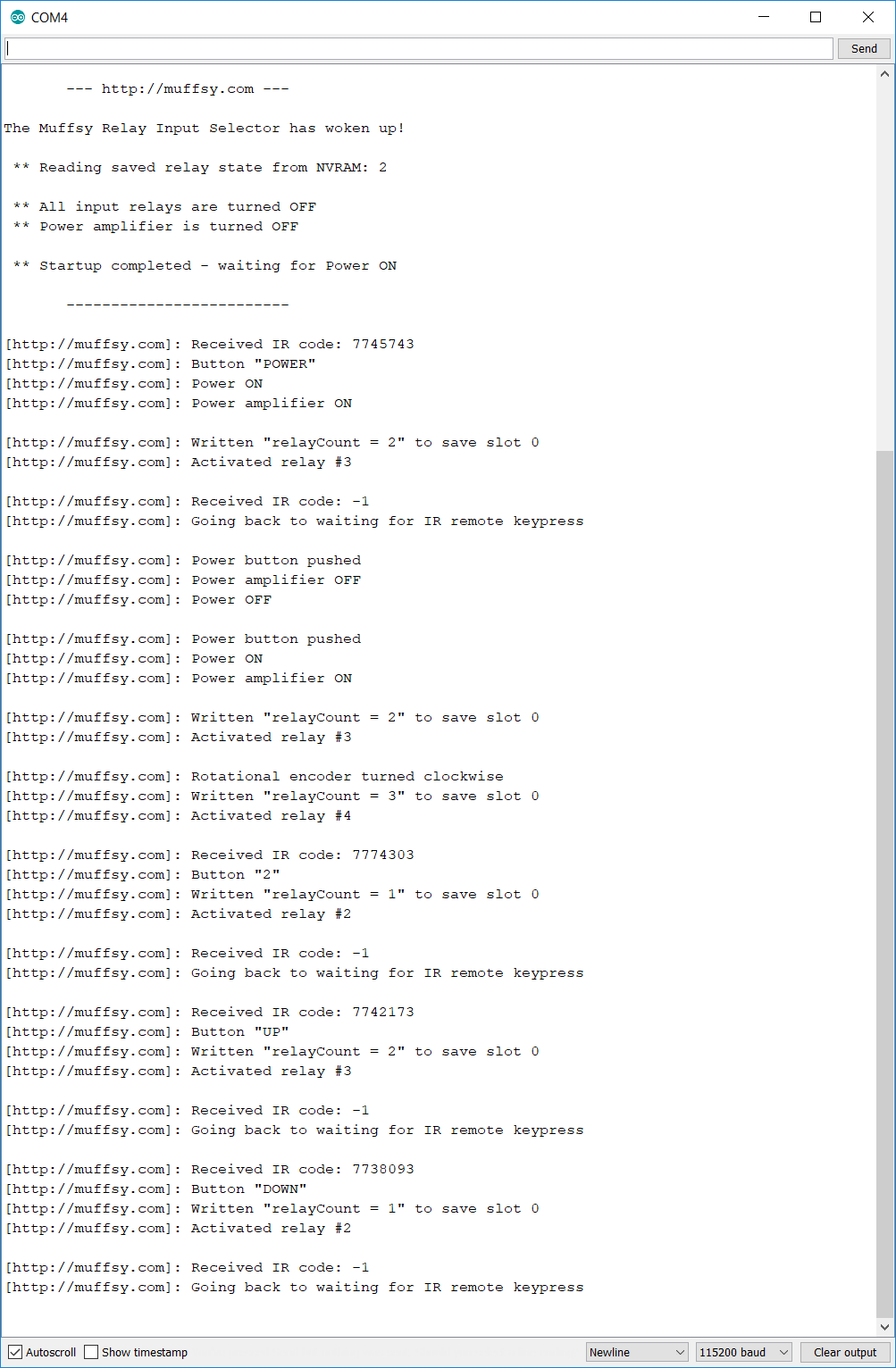
You can get an idea of what's going on by looking at the serial console:
![]()
-skrodahl
-
Example Code - IR Controlled SSR
11/13/2018 at 20:36 • 0 commentsThe new, smaller board can control a solid state relay (or turn on/off 5V to anything else) on port IO17. Here's some example code using an IR remote to control that port.
This code can be changed into controlling the input relays as well, of course.
Pressing one button on your remote turns the SSR on, another button turns it off. Read below to decide which buttons they are.The on-board LED lights up when the SSR is turned on.
Getting the code to compile
Note that IRremote.h won't compile unless you change it according to this forum post:
https://github.com/z3t0/Arduino-IRremote/issues/582
Change the end of IRremote.h (probably in your Documents\Arduino\libraries\IRremote folder) from:
#else
const int sendPin = SEND_PIN;
#endif
} ;
to:
#elif defined(SEND_PIN)
const int sendPin = SEND_PIN;
#endif
} ;
Note that it's only the first row that's changed, the rest is there to make sure you find the right section of the code.
IR Receiver
I've used a TSOP4838 (not sure if others will work), and connected pin 1 to IO13 on the ESP32. The IR receiver's pin 2 connects to GND and pin 3 to +3.3V.
Open the Serial Monitor in the Arduino IDE, and it will print the IR codes it receives. Use them directly in the program below, the lines are commented with "Button chosen for "ON" / "OFF". Recompile and transfer it to the ESP32.
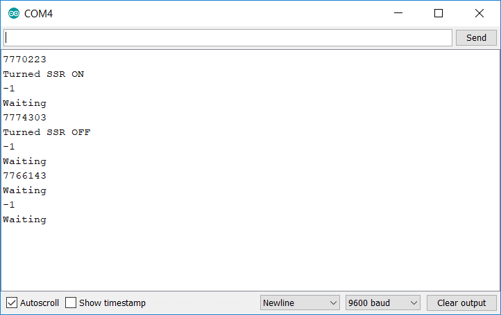
Here's me pressing "1", "2" and "3" on my remote control. "1" and "2" are already configured as "ON" and "OFF":
The first output, "7770223", is the "1"-button on my remote control. So I added it to the row that says "Button chosen for "ON"". The next number shown, "7774303", is the "2"-button on my remote. It was added to the row that says "Button chosen for "OFF"". I even pressed "3" on my remote, "7766143", but did nothing with that value.
Example Code
/* * Muffsy Relay Input Selector * Turn a solid state relay ON or OFF using IR * * Pin 1 on TSOP4838 IR receiver is connected to IO13 on the Relay Board * (Pins 2 and 3, GND and 3.3V respectively) * * 2018-11-13 http://muffsy.com * Creative Commons Attribution 4.0 International * https://creativecommons.org/licenses/by/4.0/ * https://www.muffsy.com/blogs/post/Information-on-muffsy-com-Now-Explicitly-Open-Source/ * * IRremote.h can be installed directly in the Arduino IDE, * using "Tools -> Manage library". Search for IRremote, * select the one by Ken Shiriff * * The ESP32 board on the Muffsy Relay Input Selector is called * "NodeMCU-32S" in the Arduino IDE */ #include <IRremote.h> int IR_Recv = 13; // IR Receiver, IO13 int SSR = 17; // Solid State Relay, IO17 int LED = 2; // Onboard LED, Pin IO2 int SSRState; // Declare integer variable for SSRState IRrecv irrecv(IR_Recv); decode_results results; void setup() { Serial.begin(9600); // Starts serial communication irrecv.enableIRIn(); // Starts the receiver pinMode(SSR, OUTPUT); // Sets the SSR pin as output pinMode(LED, OUTPUT); // Sets the onboard LED pin as output SSRState = 0; // Start with the SSR set to "OFF" } void loop() { // Turn SSR and LED "OFF" if SSRState is 0, "ON" if SSRState is 1 if (SSRState == 0) { digitalWrite(SSR, LOW); digitalWrite(LED, LOW); } else { digitalWrite(SSR, HIGH); digitalWrite(LED, HIGH); } // Decodes the infrared input if (irrecv.decode(&results)) { long int decCode = results.value; Serial.println(decCode); // Switch case to use the selected remote control button switch (results.value) { case 7770223: // Button chosen for "ON" { digitalWrite(SSR, HIGH); digitalWrite(LED, HIGH); Serial.println("Turned SSR ON"); // Set SSRState to 1 ("ON") SSRState = 1; break; } case 7774303: // Button chosen for "OFF" { digitalWrite(SSR, LOW); digitalWrite(LED, LOW); Serial.println("Turned SSR OFF"); // Set SSRState to 0 ("OFF") SSRState = 0; break; } default: Serial.println("Waiting"); } irrecv.resume(); // Receives the next value from the button you press } } -
Smaller version, New Software
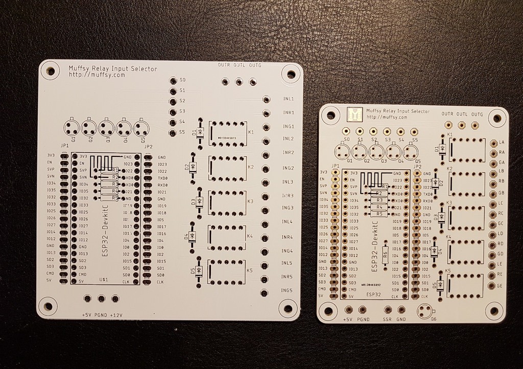
11/02/2018 at 09:22 • 0 commentsI found that I needed a smaller board, so I've shaved of about an inch of the PCB's width. It's now about the size of a standard Post-It.
I've also added another 5V controllable output on IO17, since I need to use a solid state relay to power on and off a power amp.
The Eagle design files and Gerber files are available in the Files section as MuffsyRelayInput2-Eagle.zip.
![]()
Improved software for the ESP32 is available on github.
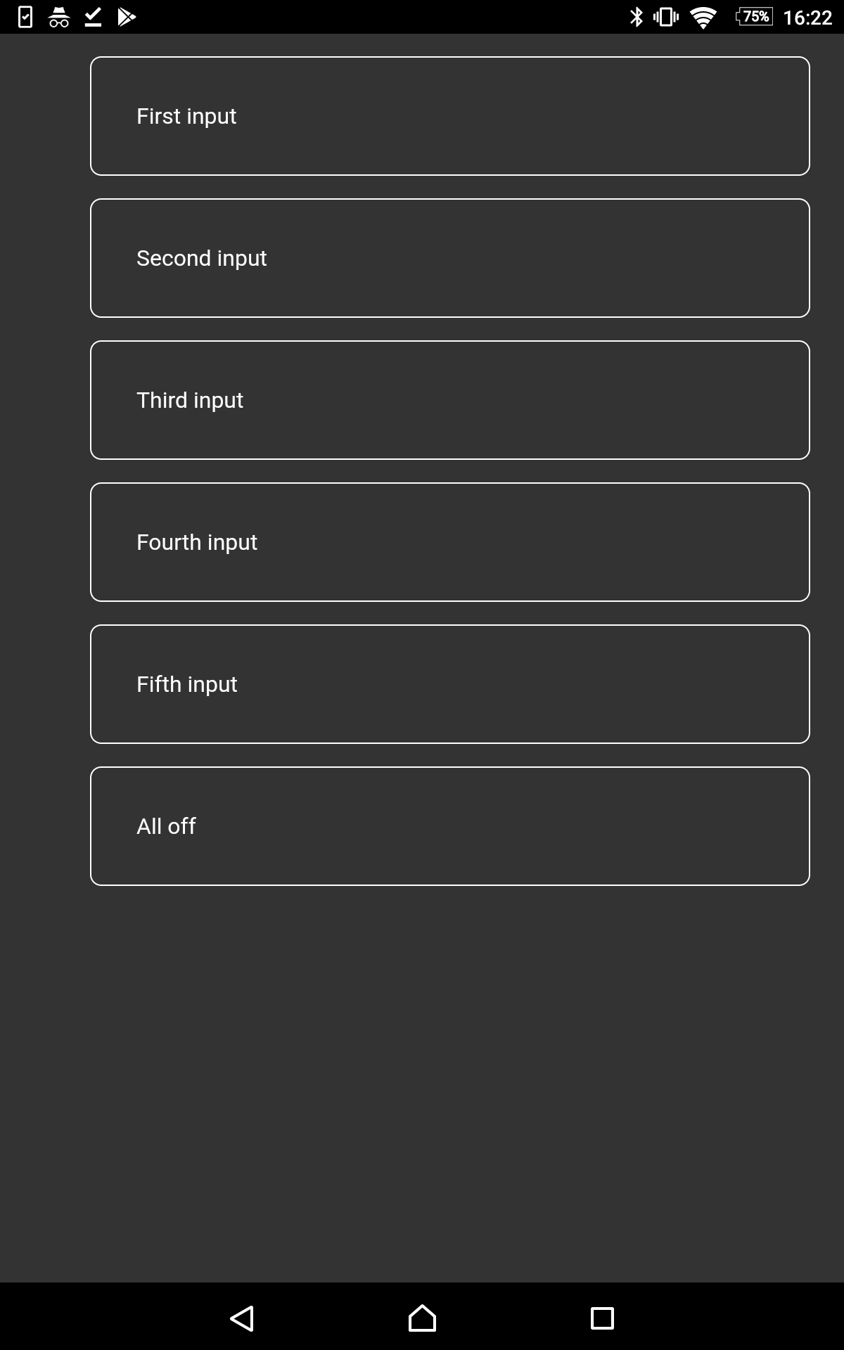
The ESP connects to your wireless networks and presents a web page with buttons to select inputs. It also has an HTTP GET API if you want to make your own web page for it.
-
Combating the 250V peak when turning off the relay
05/25/2018 at 08:01 • 0 commentsI just found this video that shows very clearly why the diodes on the relays are needed. Worst case, you'll get a 250V peak without them. This can harm your electronics, and will create very audible pops.
The Muffsy Relay Input Selector combats this by using the flyback diodes, of course, and separating the power and signal grounds. -
Lo Tech Muffsy Stereo Relay Input Selector - Without ESP32
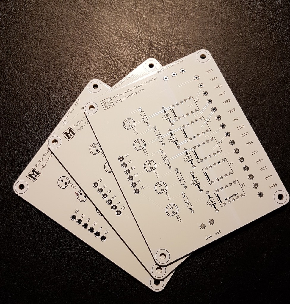
04/15/2018 at 15:22 • 0 commentsA version that excludes the ESP32 and adds LEDs has been requested. So I made one. Eagle project files and Gerbers are available in the files section.
Here it is (just imagine the drum roll first):
![]()
![]()
![]()
-
Wifi problem gives great cable for rotary switch - The Muffsy Input Switch is now fully tested
04/06/2018 at 13:27 • 0 commentsThis project log discusses using the relay board without the ESP32. There's now a board designed specifically for this: https://hackaday.io/project/46280/log/144065-lo-tech-muffsy-stereo-relay-input-selector-without-esp32
One problem with projects like these is that the wiring has a tendency to end up as a heap of spaghetti.
So I've been wondering about how I should do the rotary switch in particular (in a setup without the ESP32 module). This is the simplest setup, and you don't have to write any code at all.
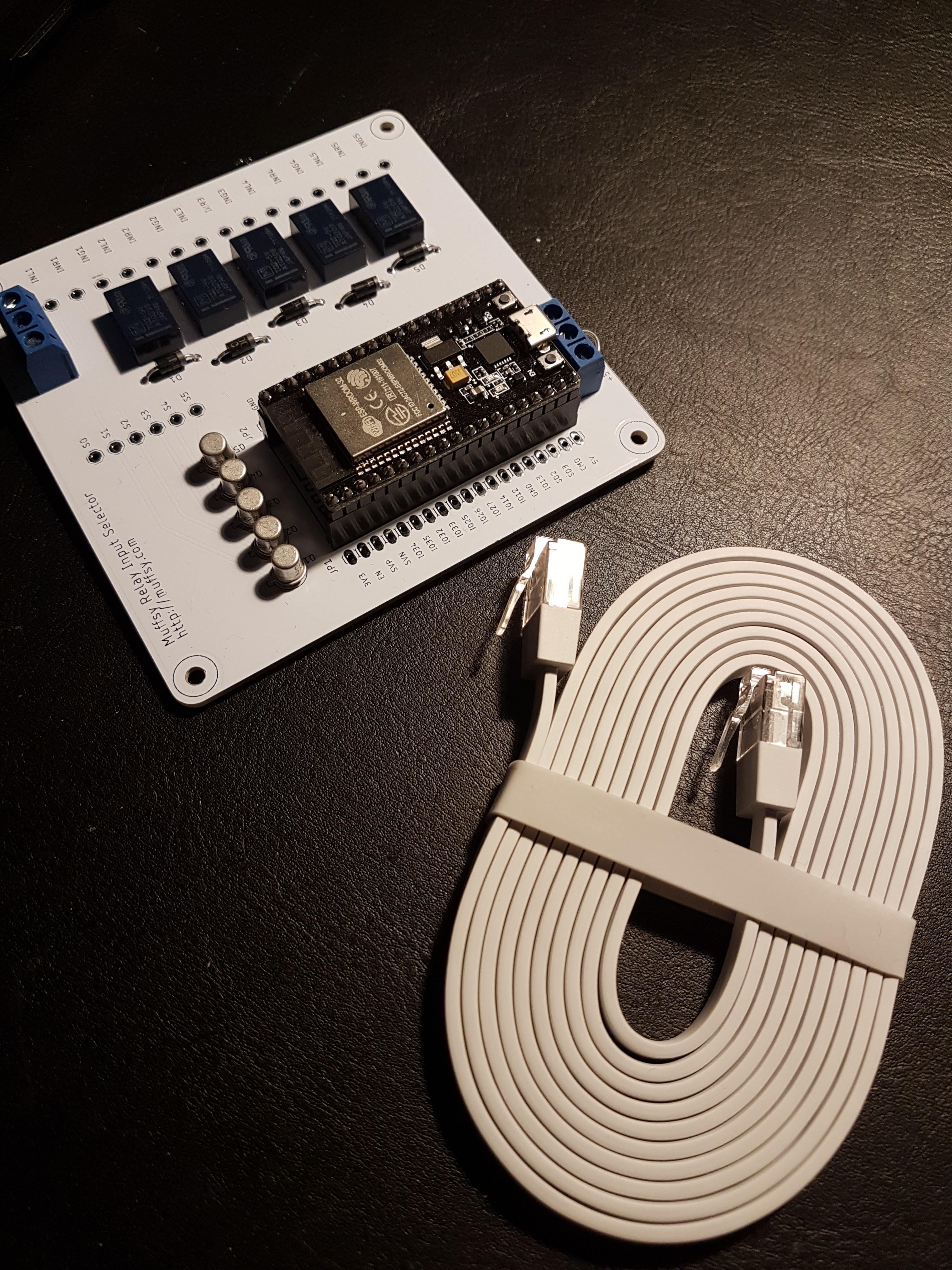
Coinciding with this, wireless coverage isn't that great in my new house. So I bought a Google Wifi bundle, and look what came with it:
![]()
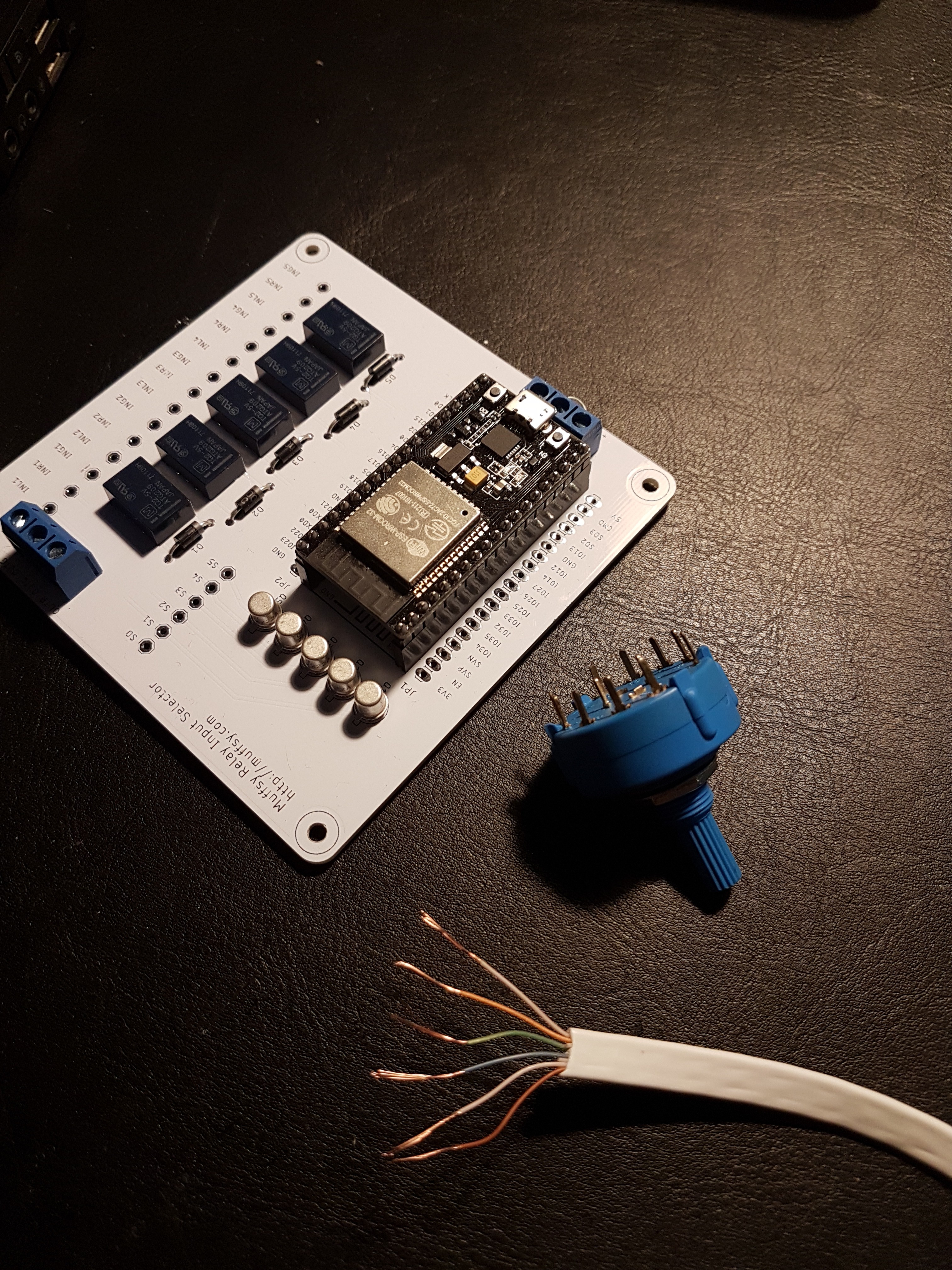
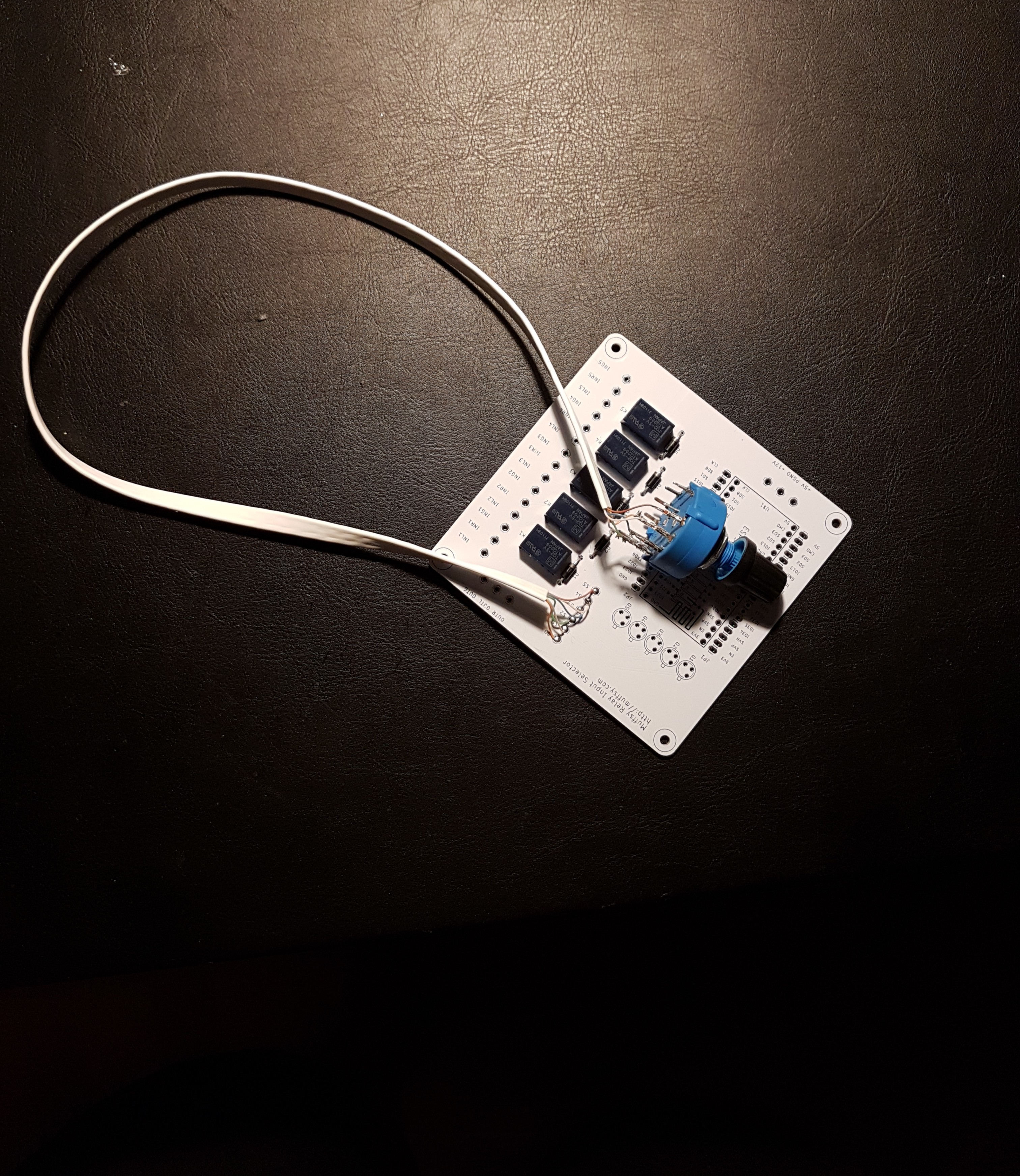
Yup, a very flat network cable. Great timing, hey? Let's get snipping!
![]()
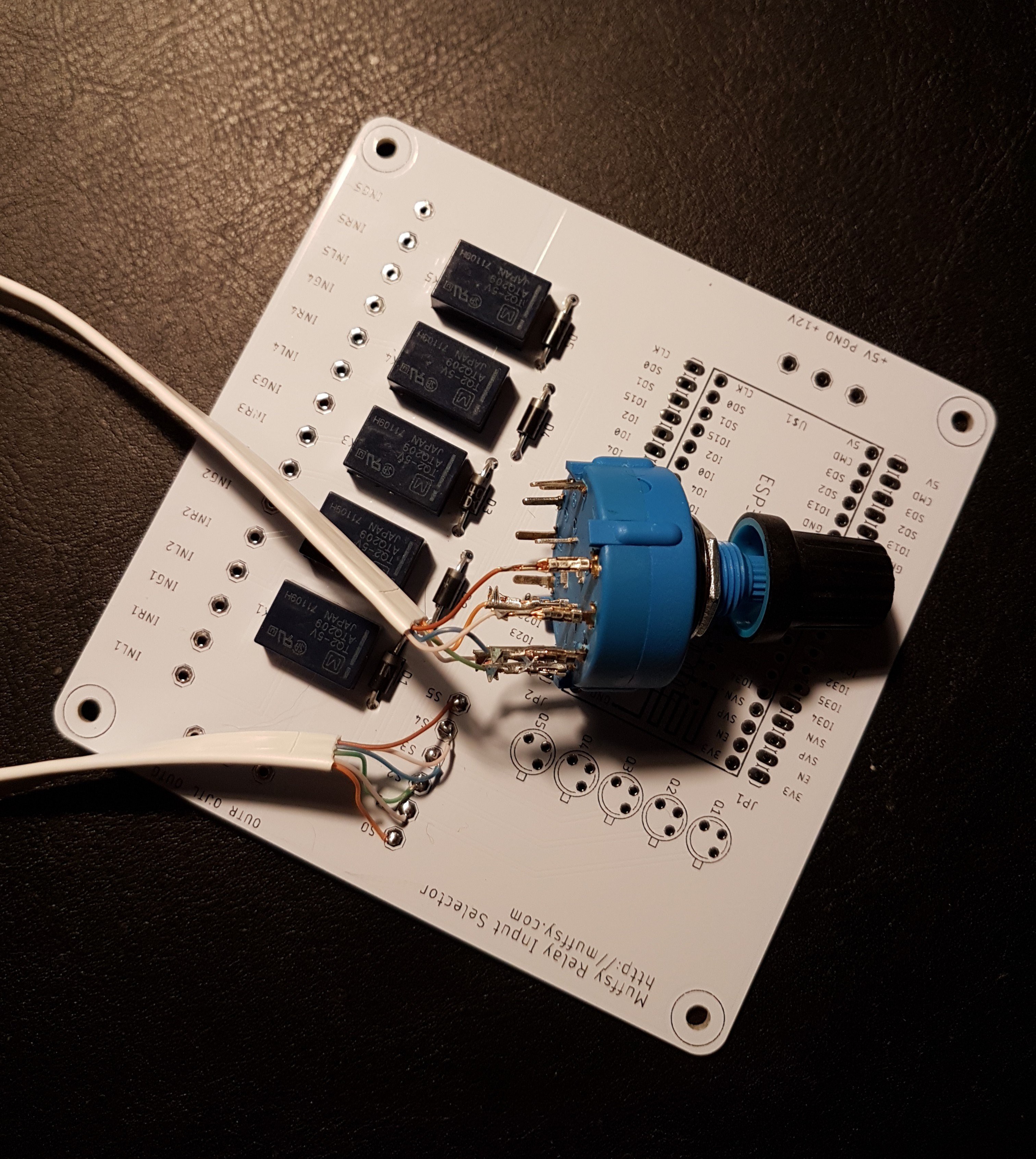
I kept the white leads on each side, and cut the white ones in the middle. The switch is 2P5T, I'll only use one of the poles. Yeah, and the ESP32 module will be removed.
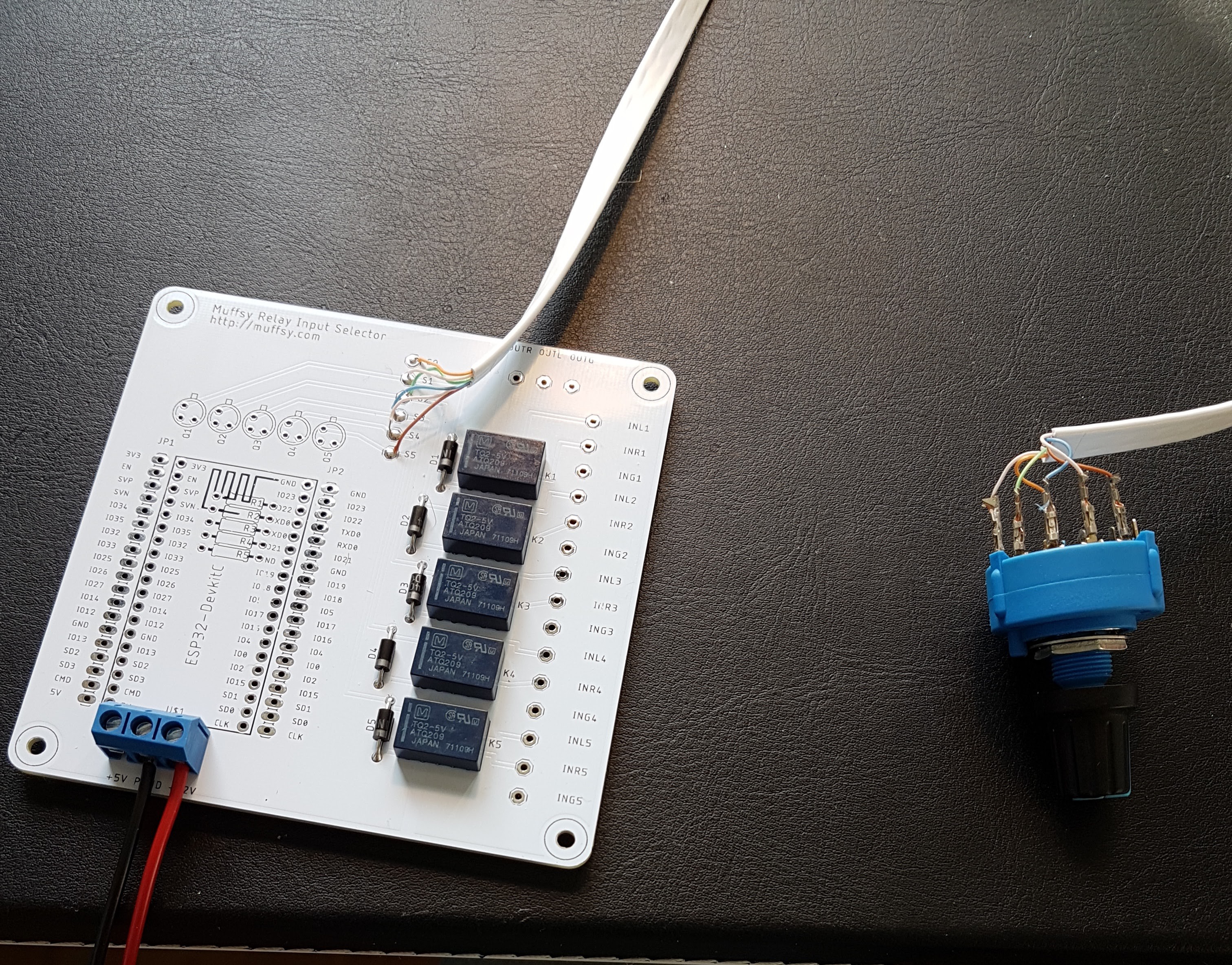
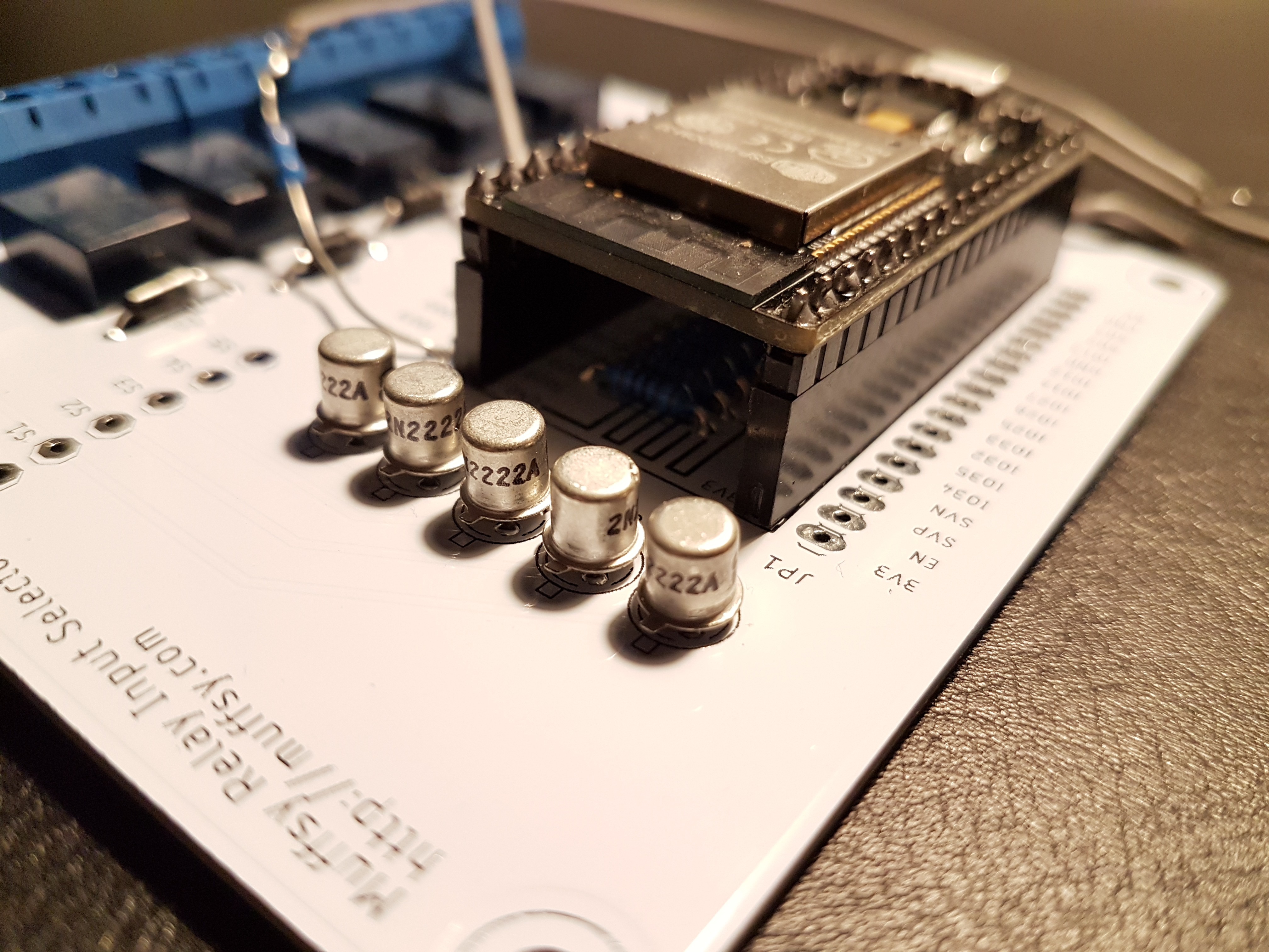
Here's the board without the ESP32 and the transistors, cable fully connected:
![]()
There are crimp connectors on the rotary switch, since it's fairly sensitive to heat (such as from a soldering iron). That's it, apart from connecting power to the relays, connect inputs and output, and cut the flat cable to the correct length.
![]()
Finally, with power connected. The rotary switch works perfectly, turn it to slowly and it will break one channel before connecting the other one. So no two channels mixed at any time.
![]()
There you have it. A stereo relay input switch that can be controlled by either an ESP32-module or a rotary switch. Fully tested and all.
-
Simple sketch - Switch between Relay1 and 2, every 4 seconds
03/31/2018 at 15:53 • 0 commentsThis sketch will:
- Define all the relays, and the ESP32's internal LED
- Turn on Relay1, blink internal LED once
- Wait four seconds
- Turn off Relay1, turn on Relay2, blink internal LED twice
- Wait four seconds, turn off Relay2 and start over
- It also writes to the serial monitor when a relay is turned on or off, and uses two different ways of blinking the LED
This shows how to turn on and off relays. Remember, you can connect an LED between the relay1-5 IO pins together with a 330 ohms resistor to GND. This LED will light up when the corresponding relay is active.
The ESP32 has the capability to store the last selected relay, so it can be selected directly if the device is turned off and on again. (not shown here)
Instead of just looping through the relays you can use push buttons, a potentiometer or a rotary encoder (and lots of other things that can hook up to the ESP32) to decide which relay is turned on.
#define LED 2 // Internal LED #define relay1 23 // relay1 on IO23 #define relay2 22 // relay2 on IO22 #define relay3 21 // relay3 on IO21 #define relay4 19 // relay4 on IO19 #define relay5 18 // relay5 on IO18 void setup() { pinMode(relay1, OUTPUT); pinMode(relay2, OUTPUT); pinMode(relay3, OUTPUT); pinMode(relay4, OUTPUT); pinMode(relay5, OUTPUT); pinMode(LED, OUTPUT); Serial.begin(115200); } void loop() { // Turn on relay1 Serial.println("Relay #1 - ON"); digitalWrite(relay1, HIGH); // Blink internal LED once digitalWrite(LED, HIGH); delay(200); digitalWrite(LED, LOW); // Wait 4 seconds delay(4000); // Turn off relay1 // Turn on relay2 Serial.println("Relay #1 - OFF"); digitalWrite(relay1, LOW); Serial.println("Relay #2 - ON"); digitalWrite(relay2, HIGH); // Blink internal LED twice for (int counter=0; counter<2; counter = counter+1){ digitalWrite(LED, HIGH); delay(200); digitalWrite(LED, LOW); delay(200); } // Wait 4 seconds delay(4000); // Turn off Relay2 Serial.println("Relay #2 - OFF"); digitalWrite(relay2, LOW); } -
Eagle Project Files and Gerbers
02/26/2018 at 15:13 • 0 commentsEagle project files and Gerbers are now available in the files section.
-
First Test of Audio Switching - Success
02/25/2018 at 21:30 • 0 commentsThe ESP32S is now mounted on pin headers:
![]()
Testing with an oscilloscope and the QA401 audio analyzer reveals that there's no switching noise, nor any clicks or pops injected in the audio channels. And, it does of course switch the left and right stereo channels. :)
Muffsy Stereo Relay Input Selector
Open Source, versatile audio relay input selector controlled by an ESP32
