-
Boards Received and Assembled
02/19/2018 at 21:11 • 0 commentsThe slow boat parked outside my house today and brought with it some shiny white PCBs.
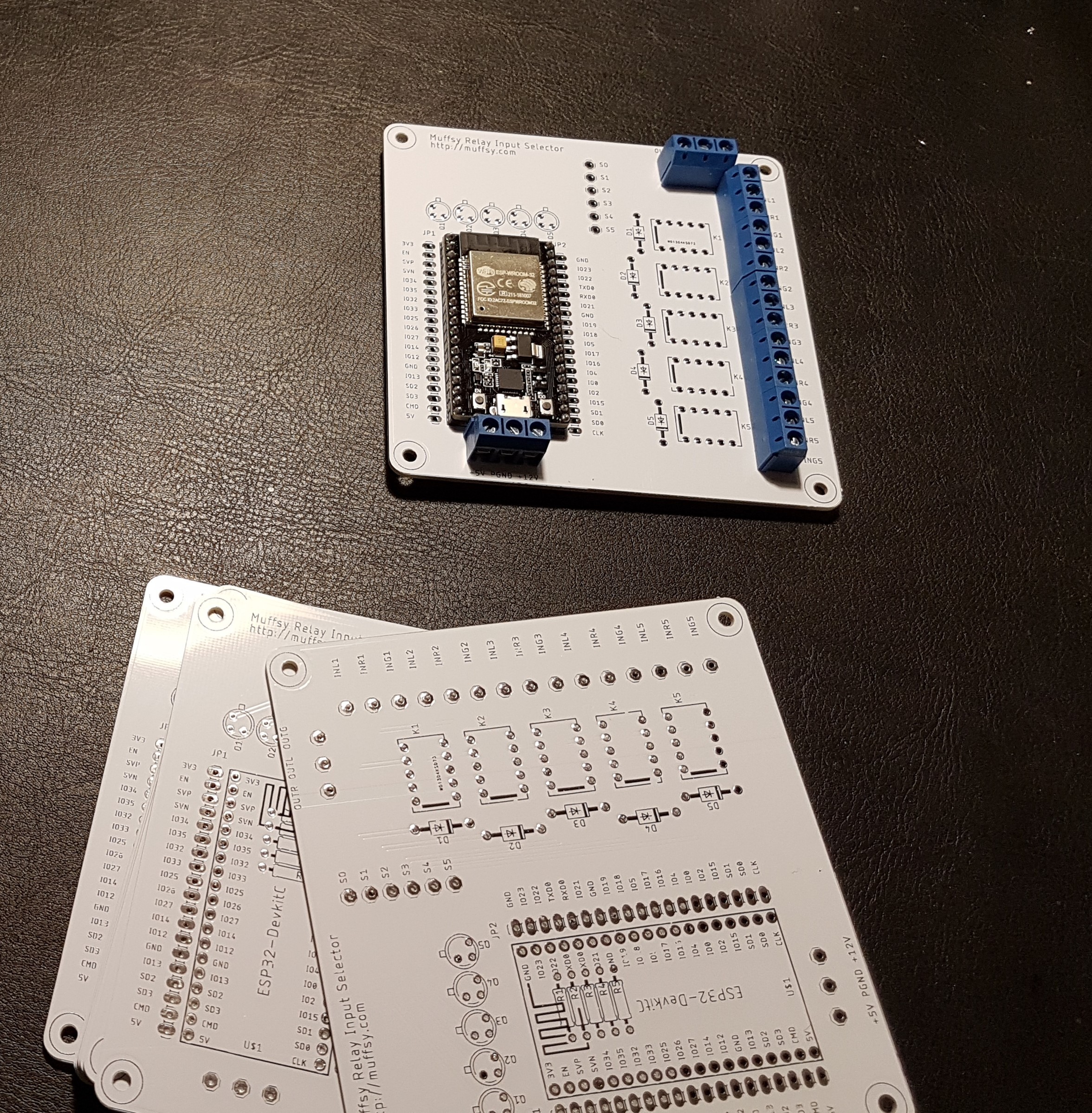
As you can see from the pictures, it's already built. The board was tested successfully using a short loop turning the relays on sequentially. I was able to verify that each relay turned on and off using the continuity tester on my multimeter.
This first picture shows a test mounting of the ESP32S and the terminal blocks for signal input/output.
![]()
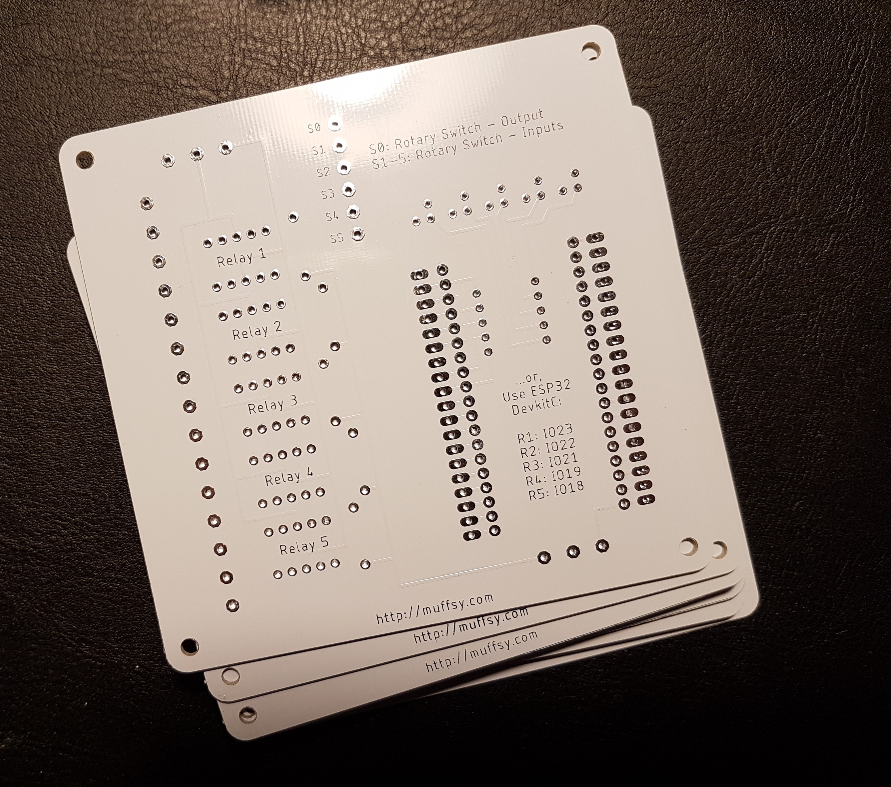
A first for me, silk screen on the back:
![]()
Stuffing the board was a quick job. Since my pin headers haven't arrived yet (and I am quite excited to see if it works), I soldered the ESP32S to the board.
I need to either skip the terminal block for input power, or be really convinced that my programming is correct before I mount it. The screw terminals will block the USB connector of the ESP when in place. Of course, I am going to build a few more, so I might just consider this the prototype.
Here's the completed board, without any kind of sensors or mechanics for actually switching channels:
![]()
-
Project Coder: Zeev Glozman
02/09/2018 at 11:12 • 0 commentsI am not the best programmer there is, so I'm happy to say that @Zeev Glozman kindly volunteered to do the ESP32 coding for this project.
Thanks Zeev!
-
Test - Controlling a relay with ESP32
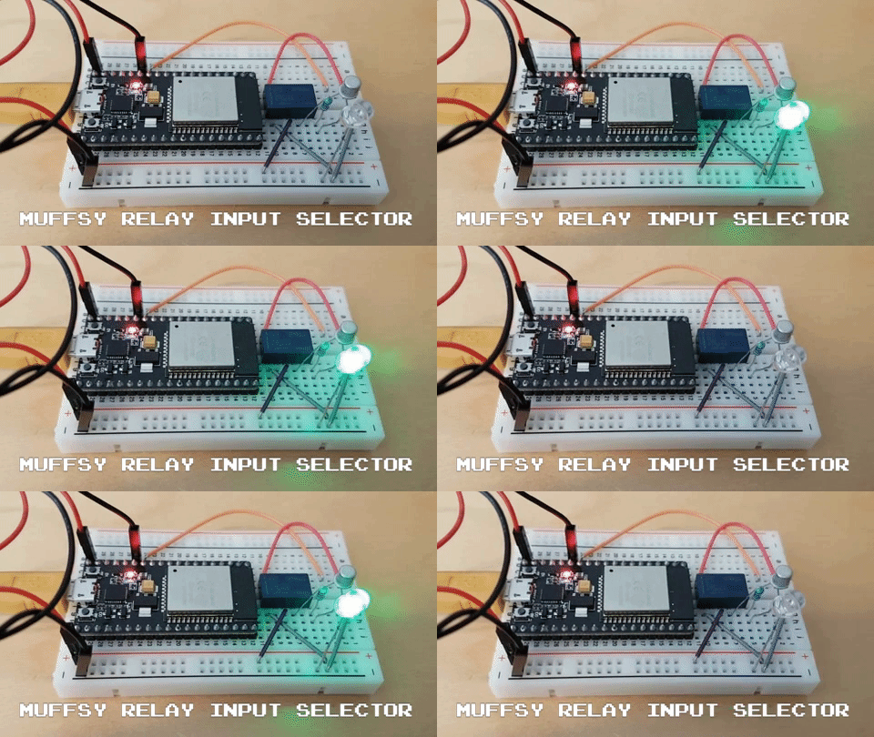
02/05/2018 at 09:21 • 0 commentsThe ESP32 switches the relay on and off, just as a proof of concept:
![]()
-
ESP32S Devkit - Eagle Library
02/04/2018 at 22:38 • 10 commentsI couldn't find the footprint for the ESP32S Devkit anywhere, so I made my own.
You'll find it in the files section.
![]()
-
Schematic
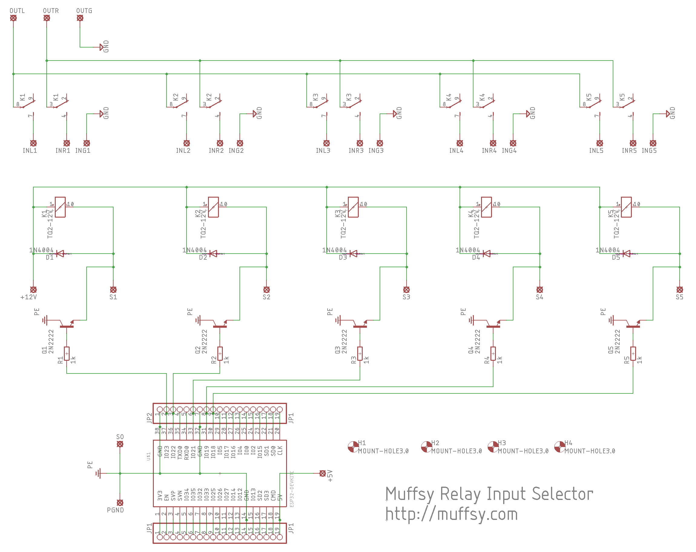
02/04/2018 at 22:27 • 0 commentsHere are the five relays, all controlled by the ESP32 (or a rotational switch, using S0 to S5, S0 being the center pin).
Five stereo inputs, one stereo output.
The ESP32 switches the relay power to GND using transistors connected to IO23, IO22, IO21, IO19 and IO18.
Power ground and signal ground are separate.
![]()
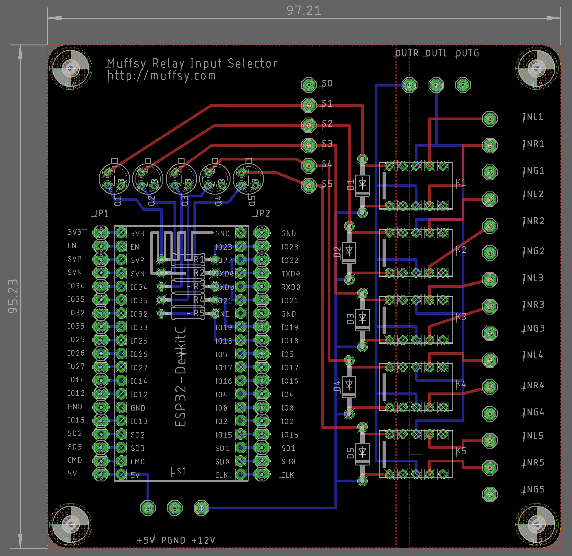
Here's the routed board with dimensions in mm:
![]()
Power inputs and signal inputs/output have 5.08 mm pitch (0.2") to accomodate screw terminals.
The solder pads for the rotational switch (S0-25) and ESP32 break-outs have 2.54 mm pitch (0.1").
Muffsy Stereo Relay Input Selector
Open Source, versatile audio relay input selector controlled by an ESP32
