Close
0%
0%

Nixie Clock #3

a Nixie Clock using Burroughs 5870ST tubes.

Similar projects worth following
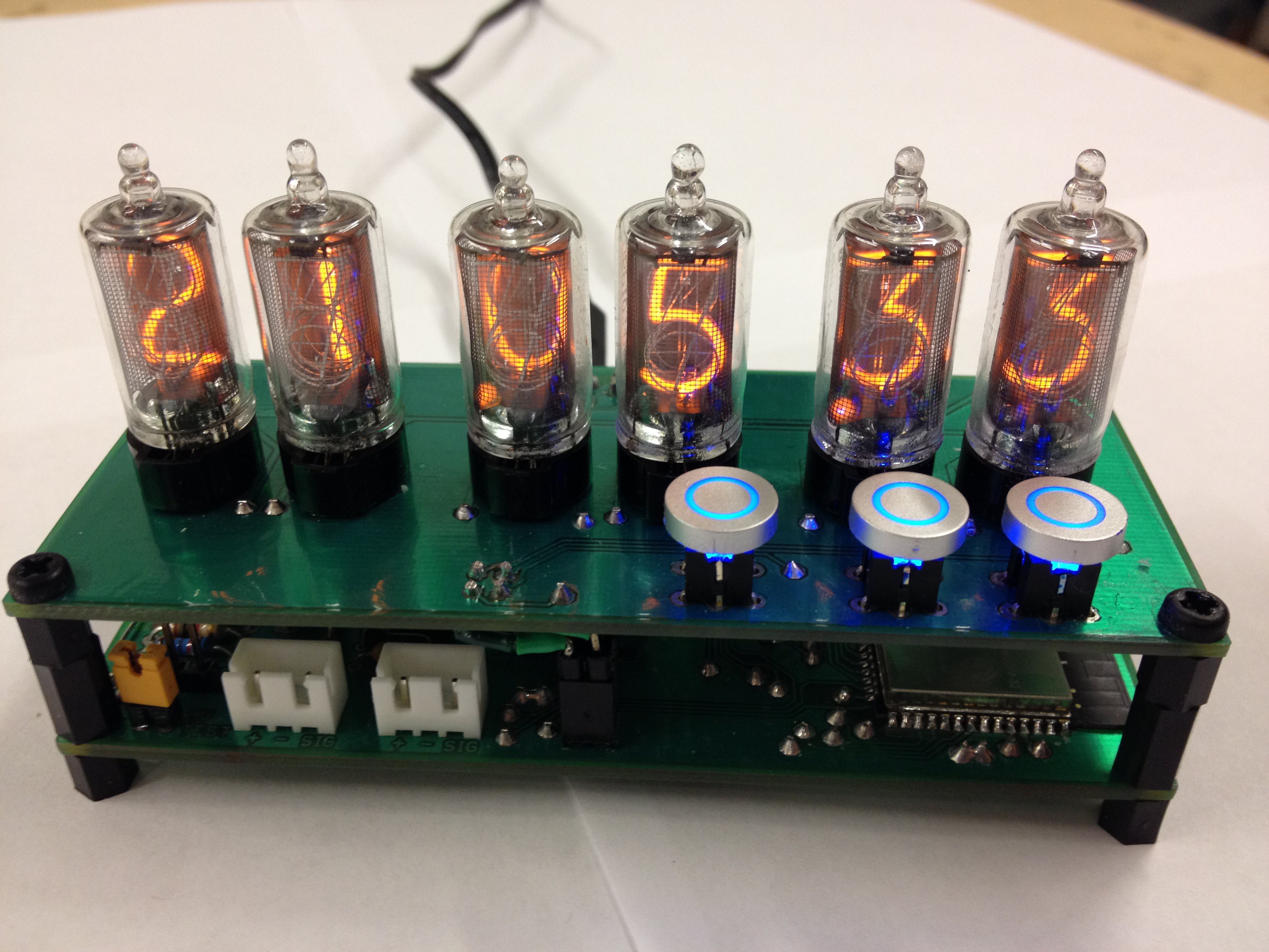
Currently working on my 3rd Nixie Clock. This time using some Burroughs 5870ST tubes. My previous clocks used Soviet tubes (IN12 and IN8)

The clock comprises two circuit boards.  There's a board that holds the tubes and buttons.  There's another board that has the power supply and other various components.  The high voltage power supply I copied from a kit I got from ebay.  I simply copied the circuit into my schematic and used the components from the kit on the PCB I made.

My first clocks used the common Russian driver chips and I used multiplexing in order to achieve dimming of the tubes.

This time I wanted to use some HV5530 chips that I had read about from other people using them for clocks.  They work really well and are a LOT simpler to integrate and dimming is achieved by the ability for the chip(s) to blank.  So it's a straight forward matter to just vary the tubes on and off cycles via this blanking feature.

So from there all I had to do was design the rest of the circuit and make a couple circuit boards and then assemble it.


I Tested the look of it with a piece of black acrylic which seems to look pretty decent.


Now I need to make some sort of case for it!
tube_board.sch.pdf

PDF version of the tube board schematic NOTE: where it says 5V on this board is actually 3.3V

Adobe Portable Document Format - 30.95 kB - 02/17/2018 at 03:21

Preview

main_board.sch.pdf

PDF Version of the main board schematic

Adobe Portable Document Format - 29.29 kB - 02/17/2018 at 03:21

Preview

tube_board.sch

Eagle schematic for the tube board

sch - 721.82 kB - 02/16/2018 at 21:17

Download

main_board.sch

Eagle schematic of the main board. Thanks again to the person that designed the high voltage part (i bought a kit from ebay and used that circuit in my own schematic)

sch - 1.05 MB - 02/16/2018 at 21:17

Download

  • Assembled and functioning

    myte02/16/2018 at 20:56 0 comments

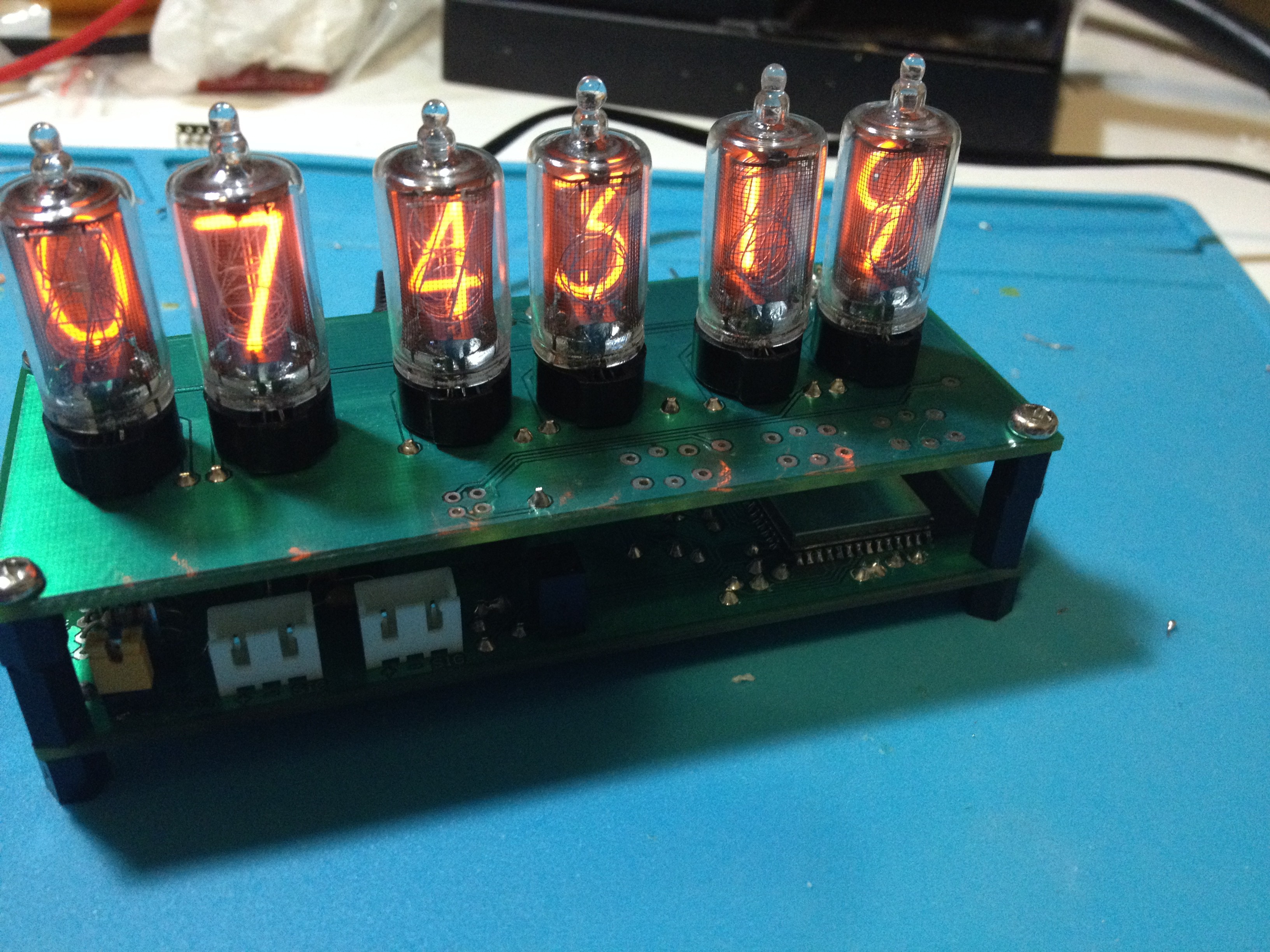
    Here's a pic after assembling and now functioning correctly.

    At this point it gets NTP time via Wifi and I can control it via  bluetooth with an app I made for my phone that for now simply adjusts brightness of the tubes and buttons and can set the timezone and daylight savings setting for NTP time.  It can also increment hours and minutes for if I wasn't using NTP to set the time.

    There's space on the main board for some potentiometers to control brightness for tubes and buttons but I'm not sure if I Want those or am OK with adjusting via my phone or with a light sensor.

    After this I'll need to make a case for it to be housed in!

  • Assembling the tube board

    myte02/16/2018 at 20:54 0 comments

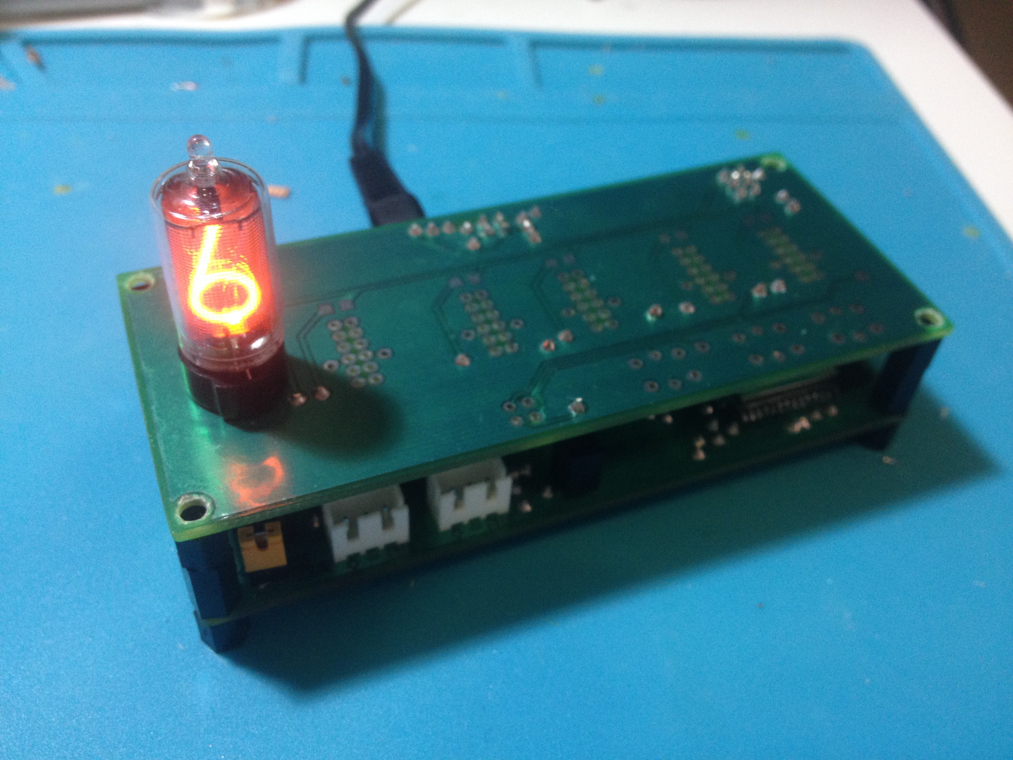
    I got the components on the board and then placed one tube so I Could test it in conjunction with the main board and make sure I Was able to actually make it display OK.

    This was the moment I had the necessary components on the tube board and a single tube placed and sorted out sending data to the HV5530 chips to make a digit display properly!  It took quite some time :)

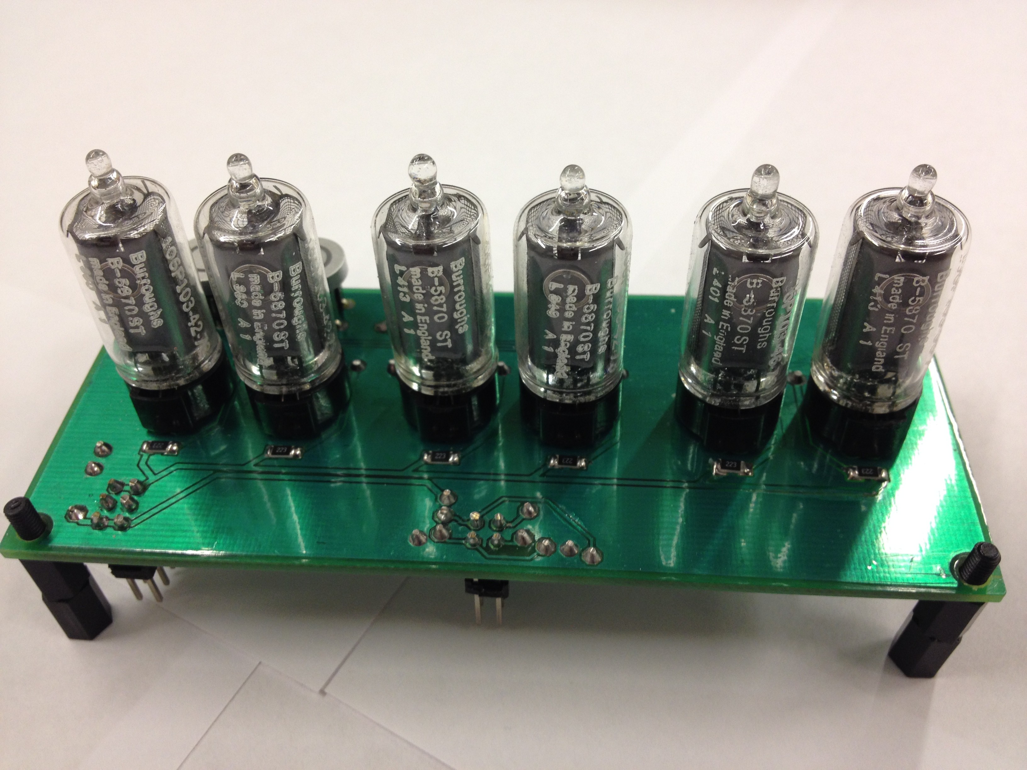
    And then after all tubes placed and tested.  This was a good day!


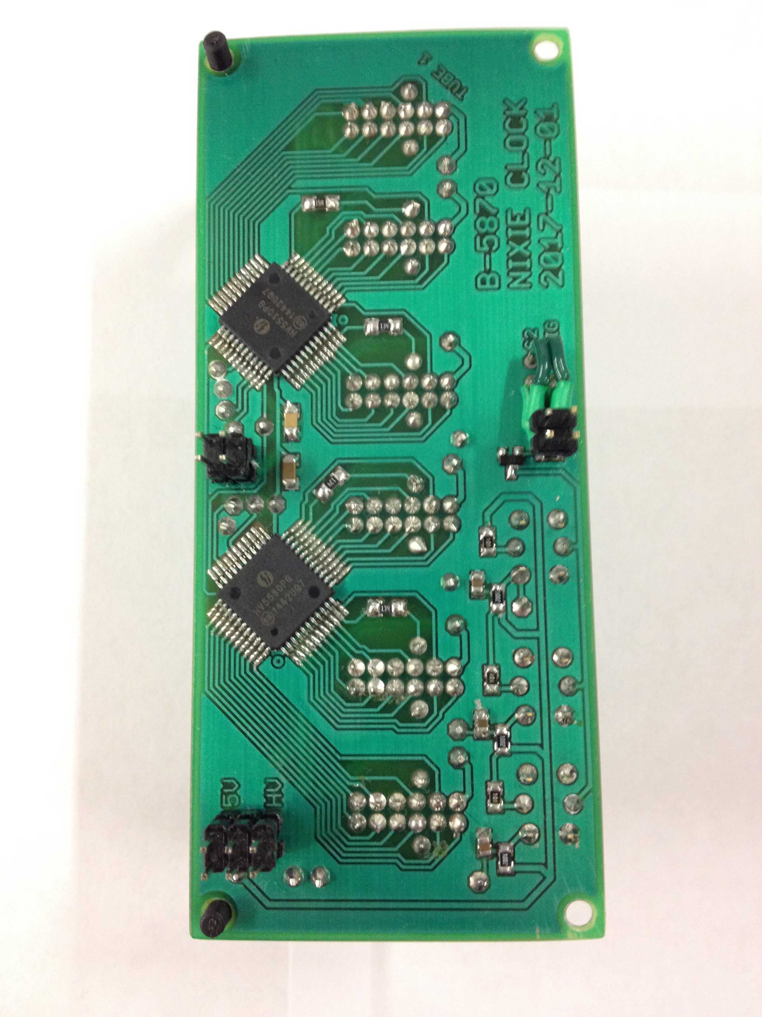
    Bottom of board after assembly was finished and everything attached.

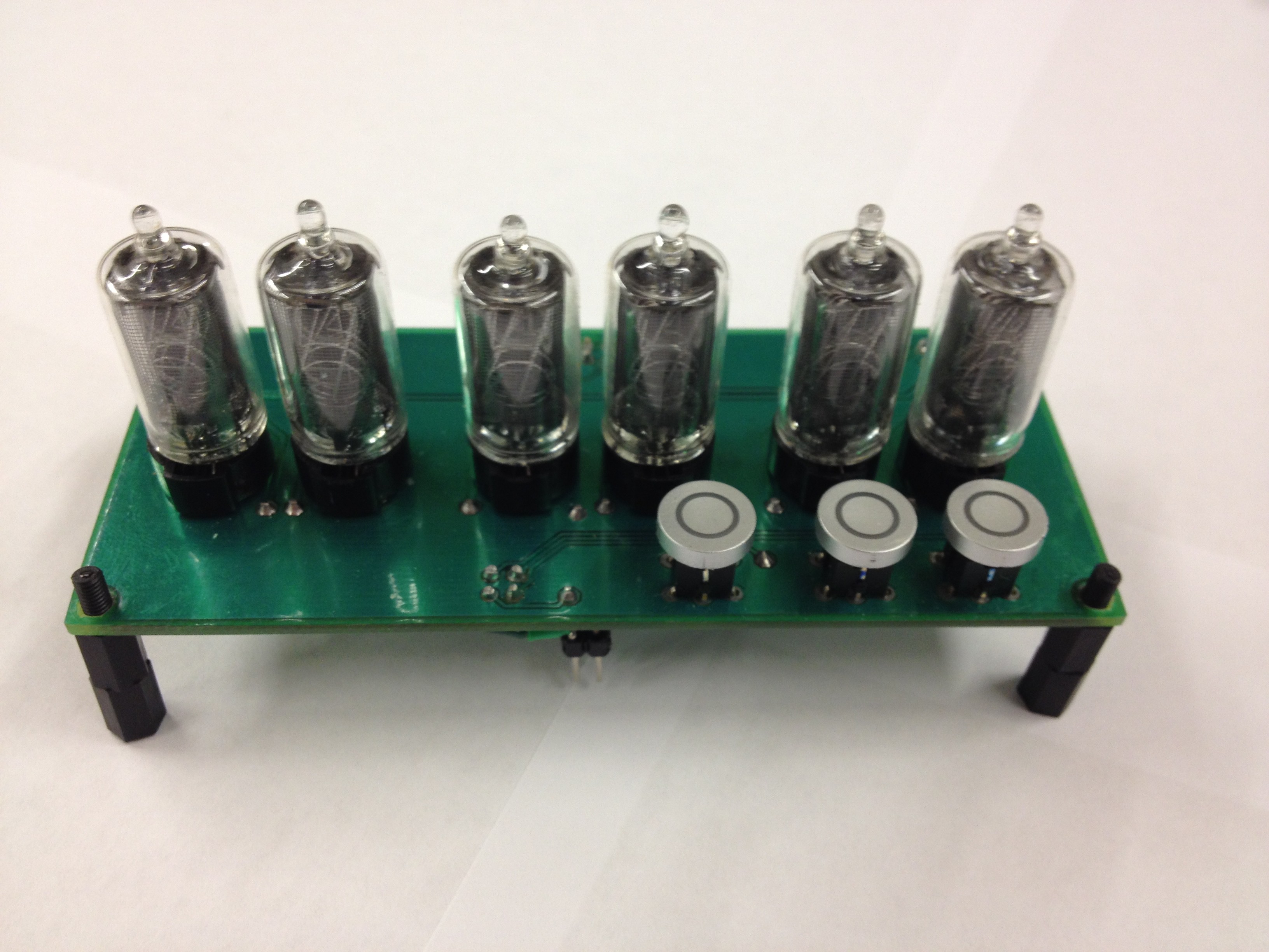
    And then a couple pics of the top of board after assembly.

    From the Front


    From the Back

  • Main board Assembled

    myte02/16/2018 at 20:44 0 comments

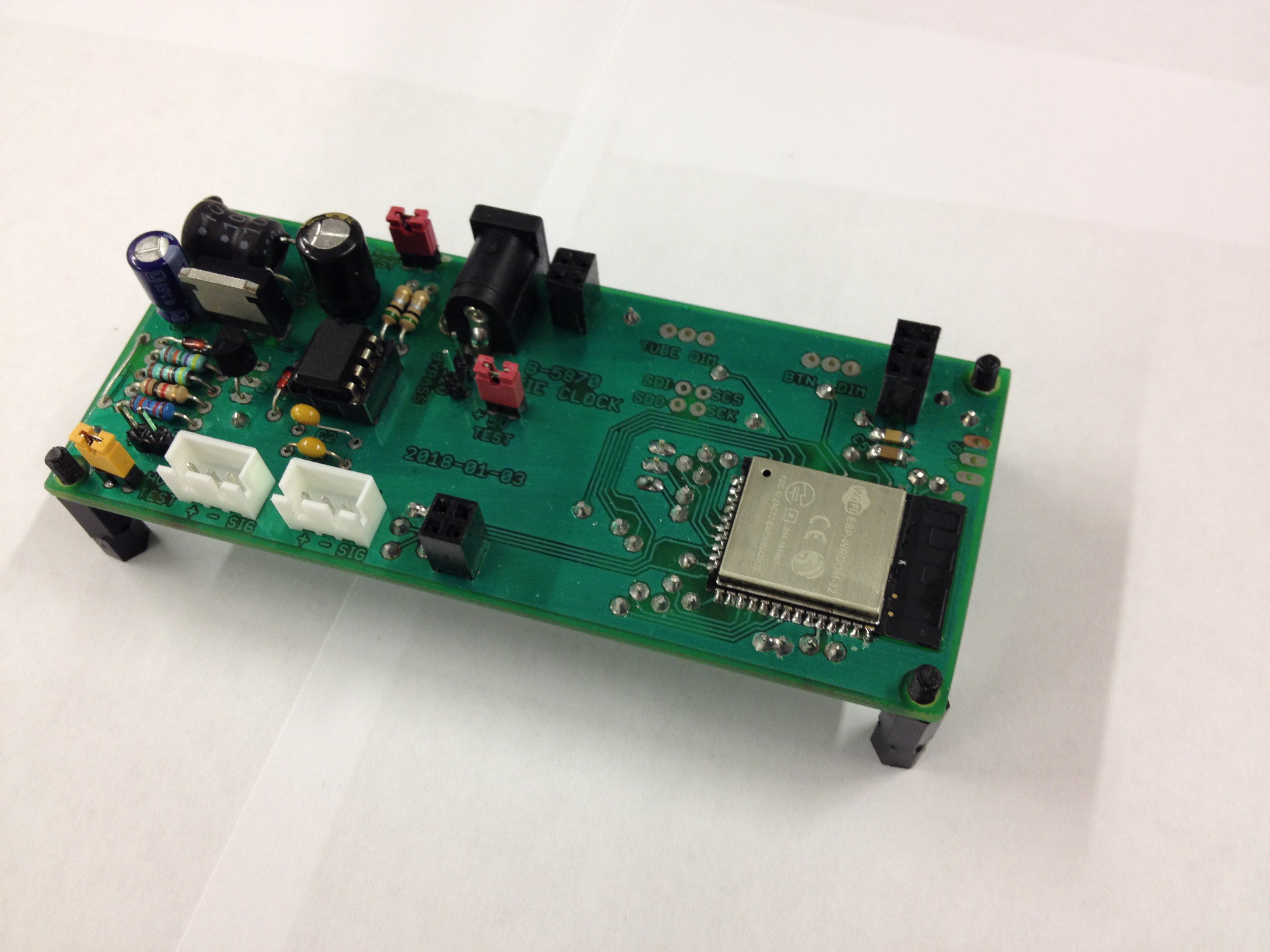
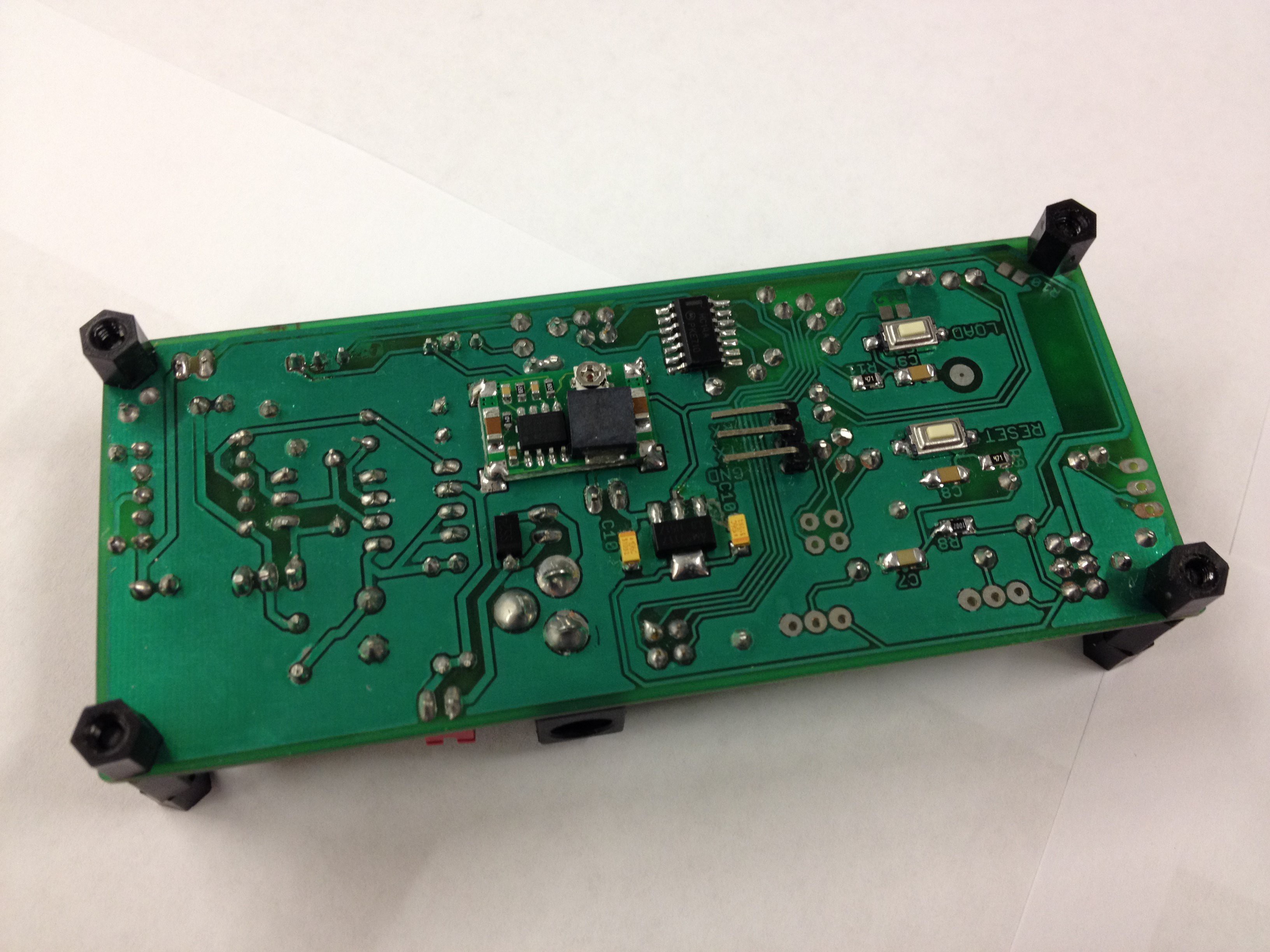
    Some pics after assembling the main board and after having tested the high voltage supply and making sure the ESP32 was functioning correctly and able to be programmed.


    Top

    Bottom

  • Making the main PCB

    myte02/16/2018 at 20:40 1 comment

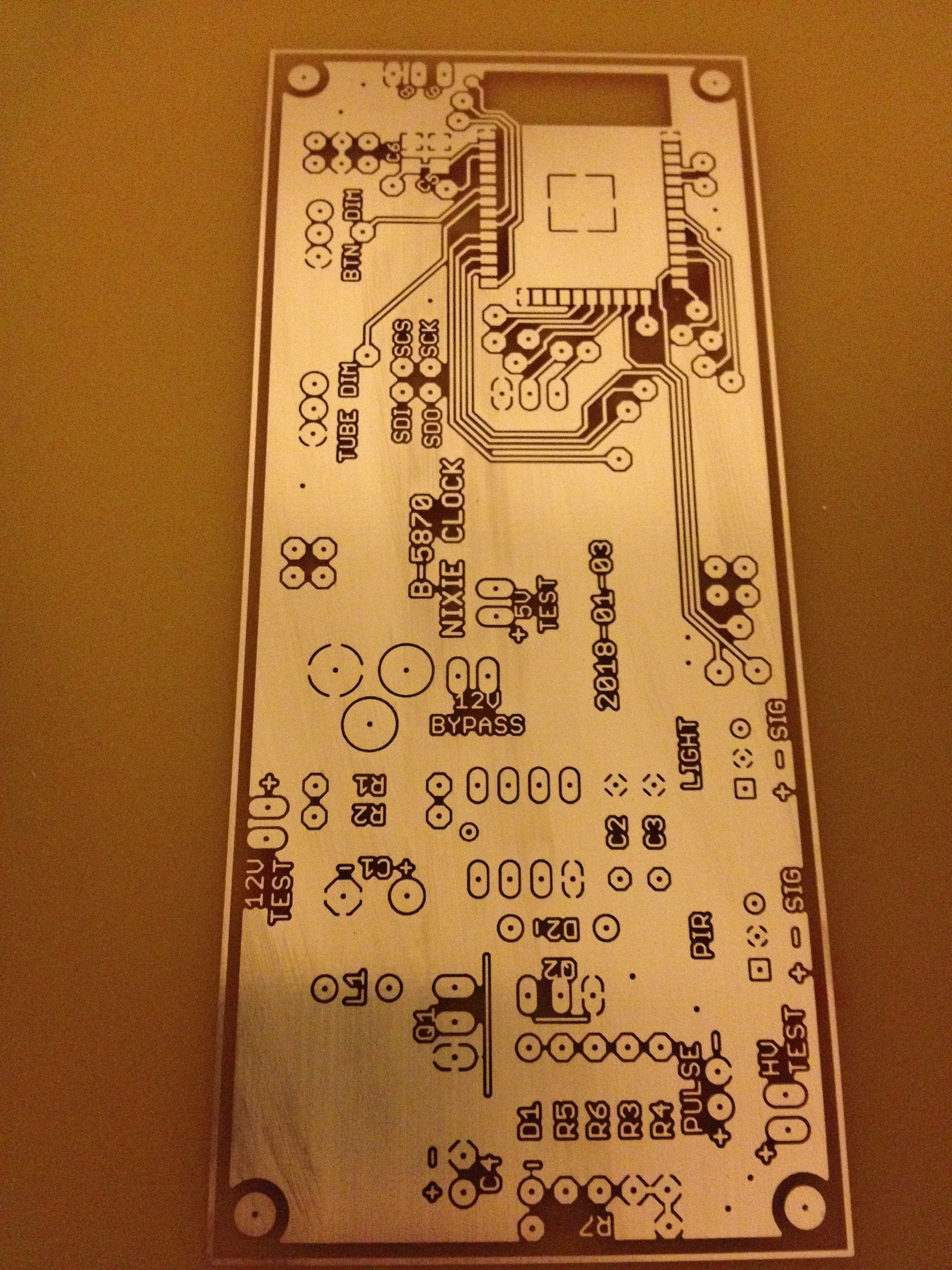
    Next came making the main PCB

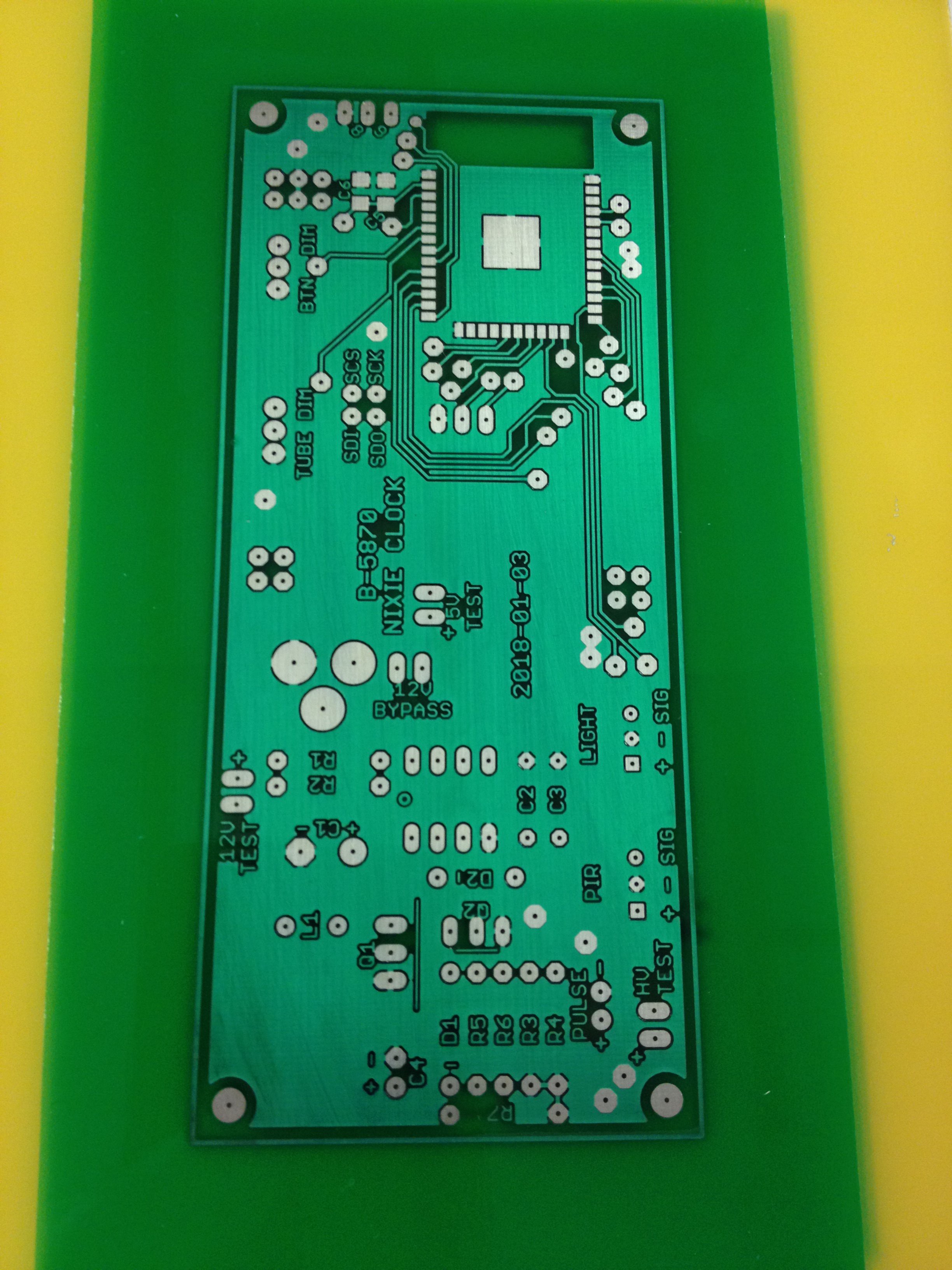
    Top after etching and tinning

    Top after applying solder mask

    Bottom after applying solder mask

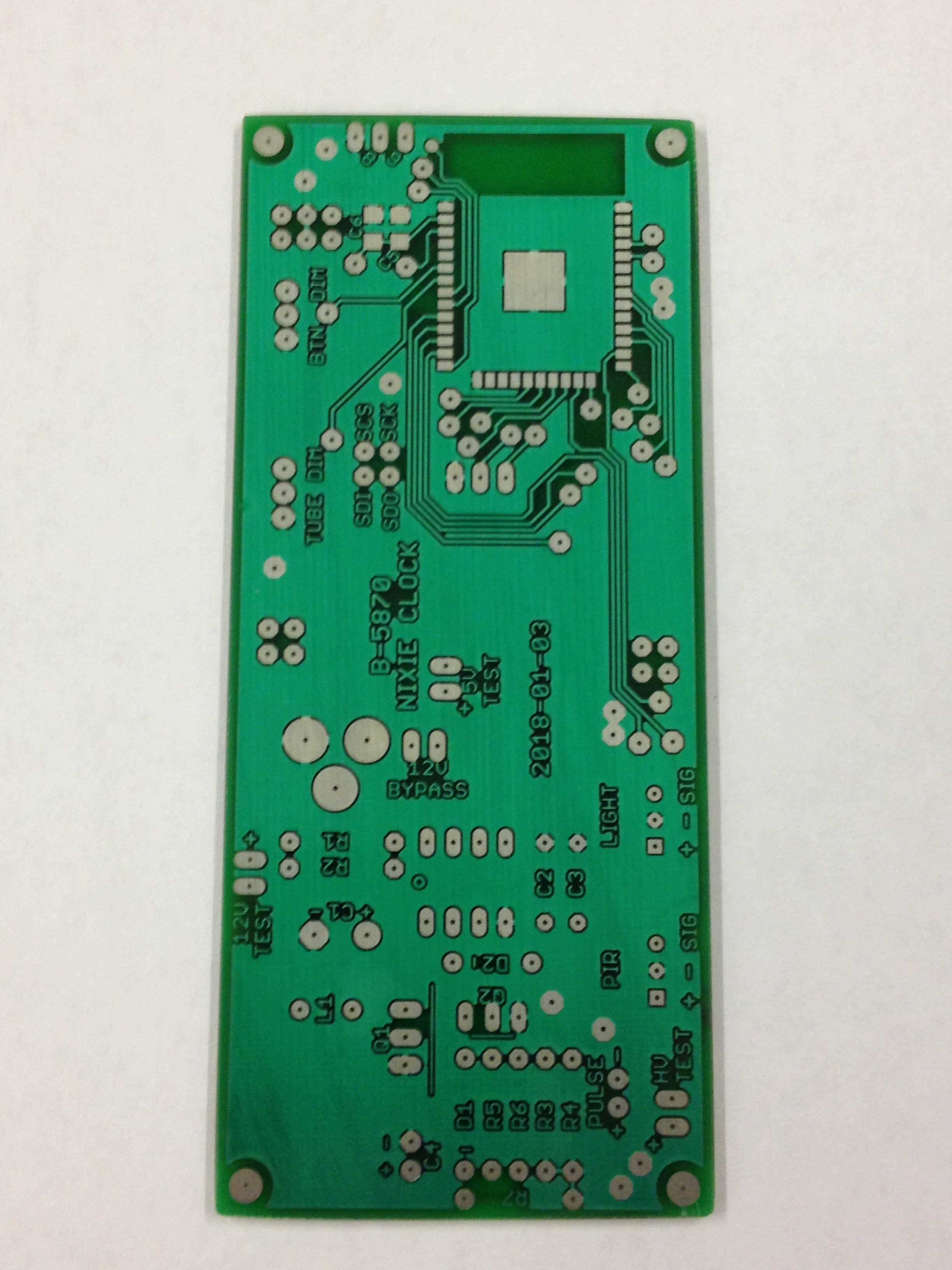
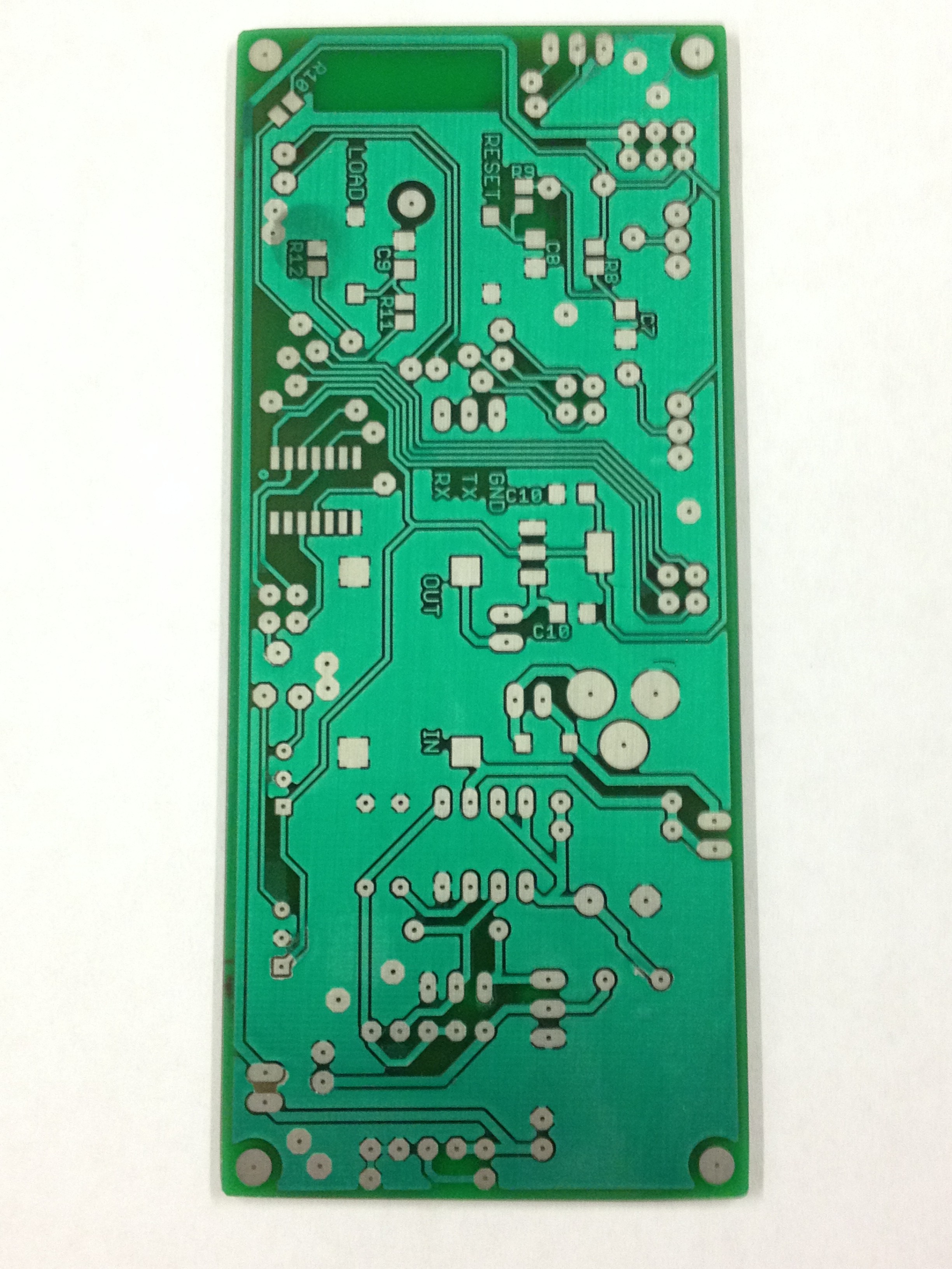
    Top after cutting to size

    Bottom after cutting to size

  • Making the PCB for the Tubes

    myte02/16/2018 at 20:35 0 comments

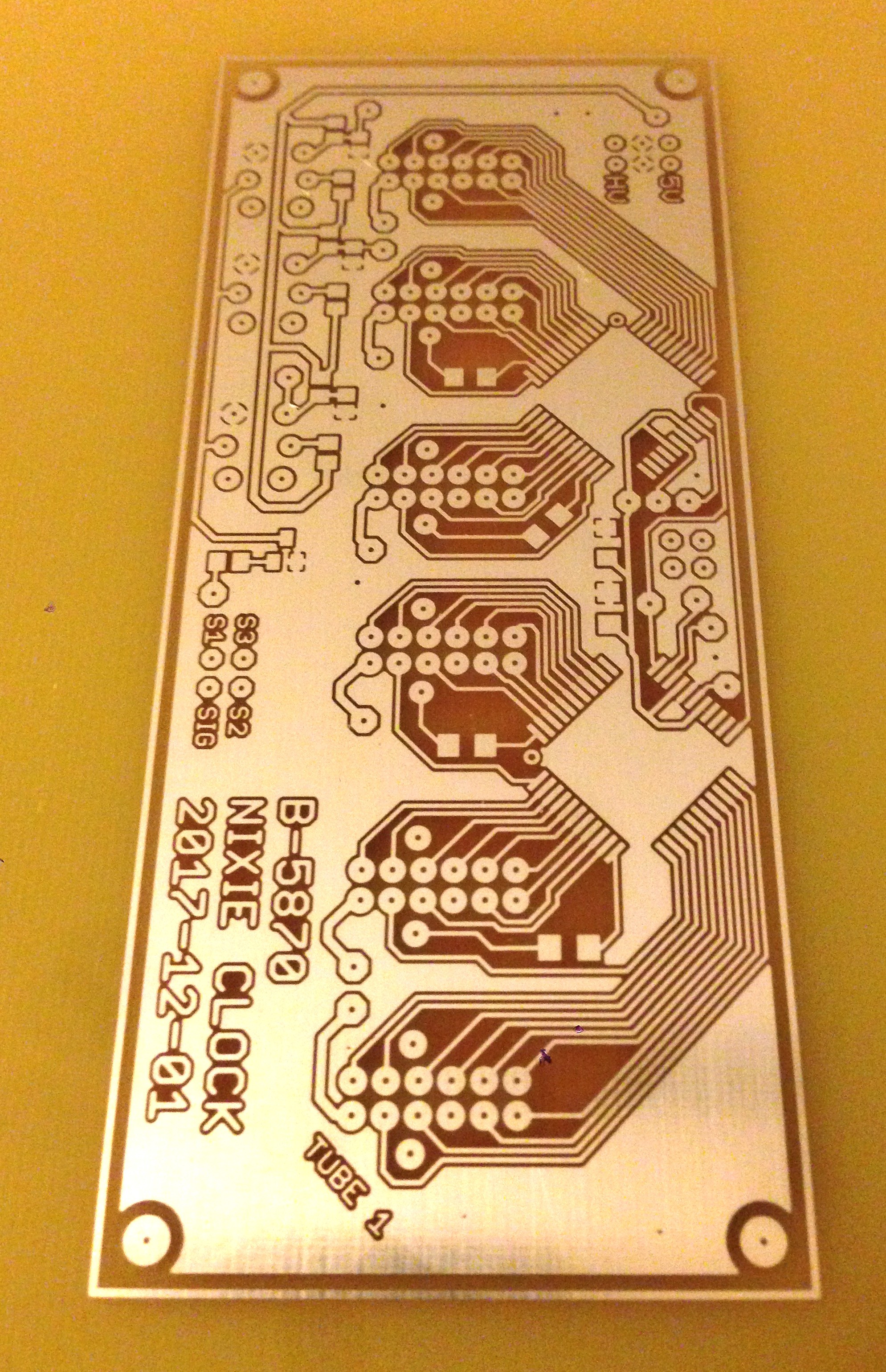
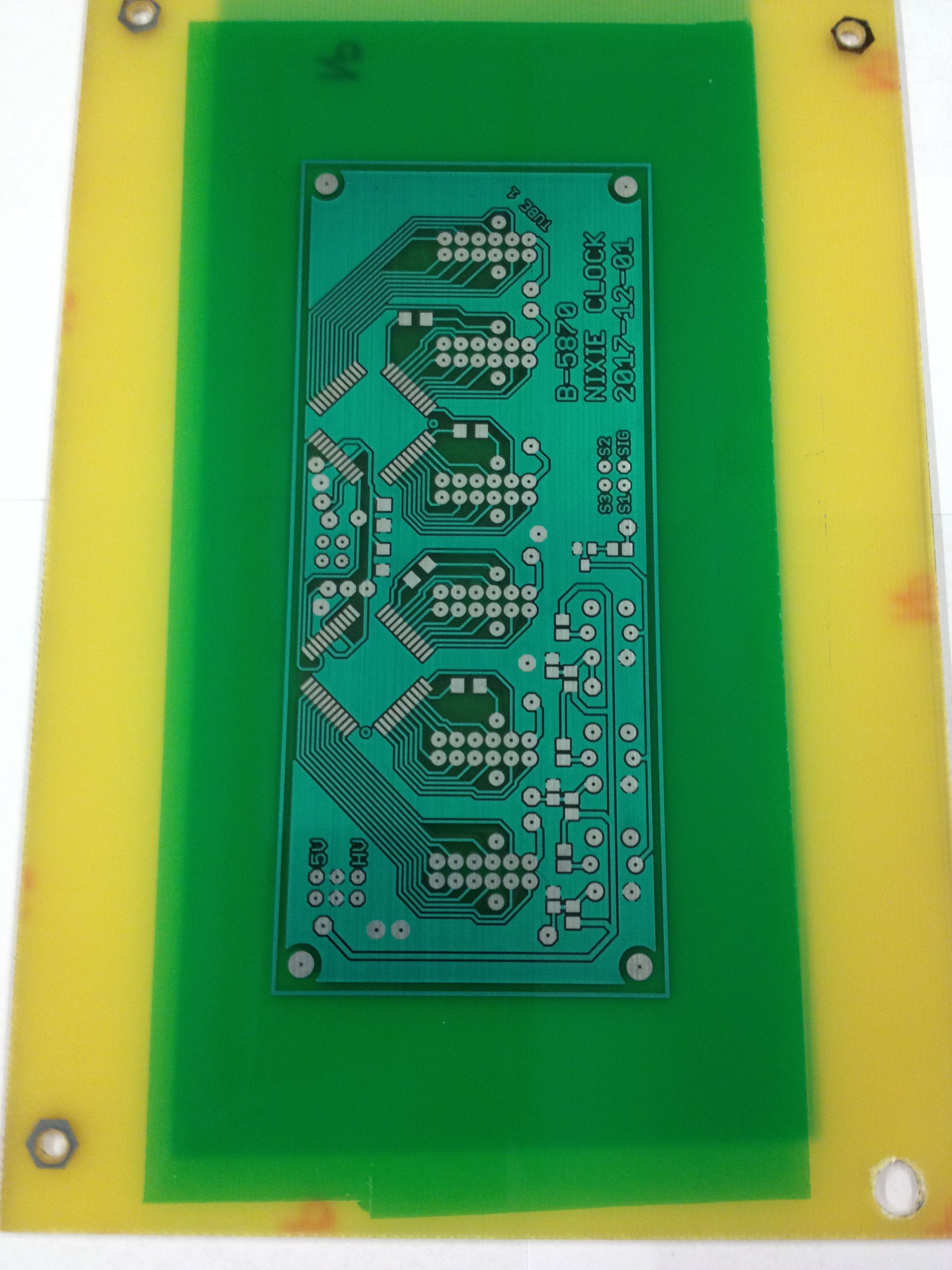
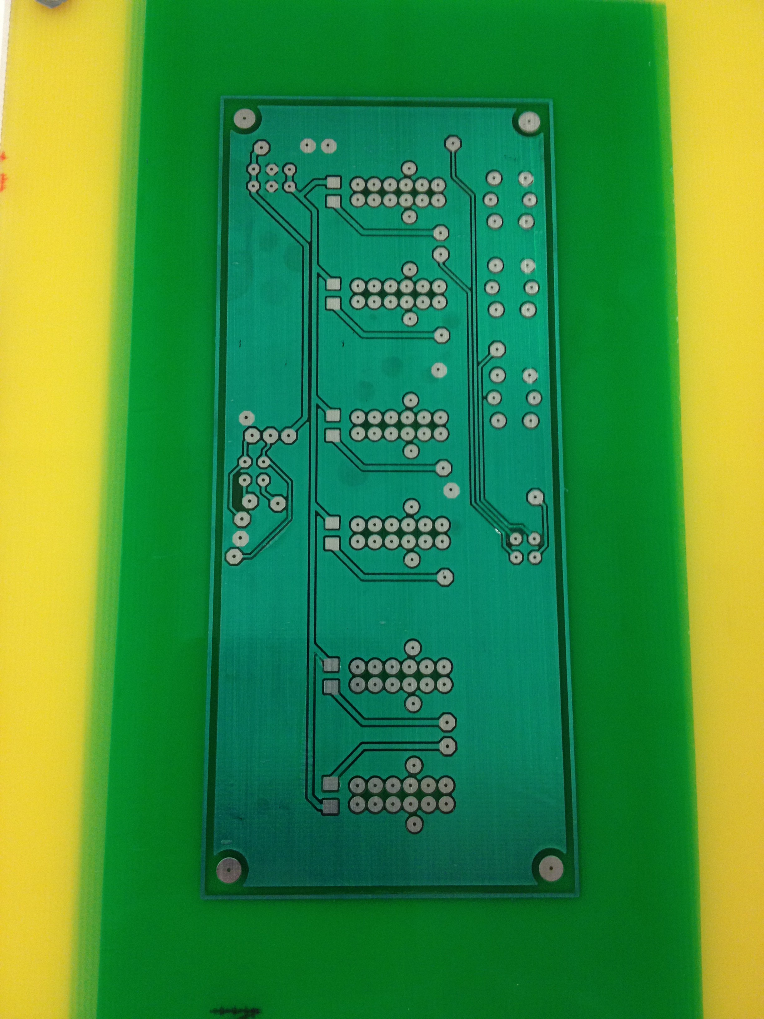
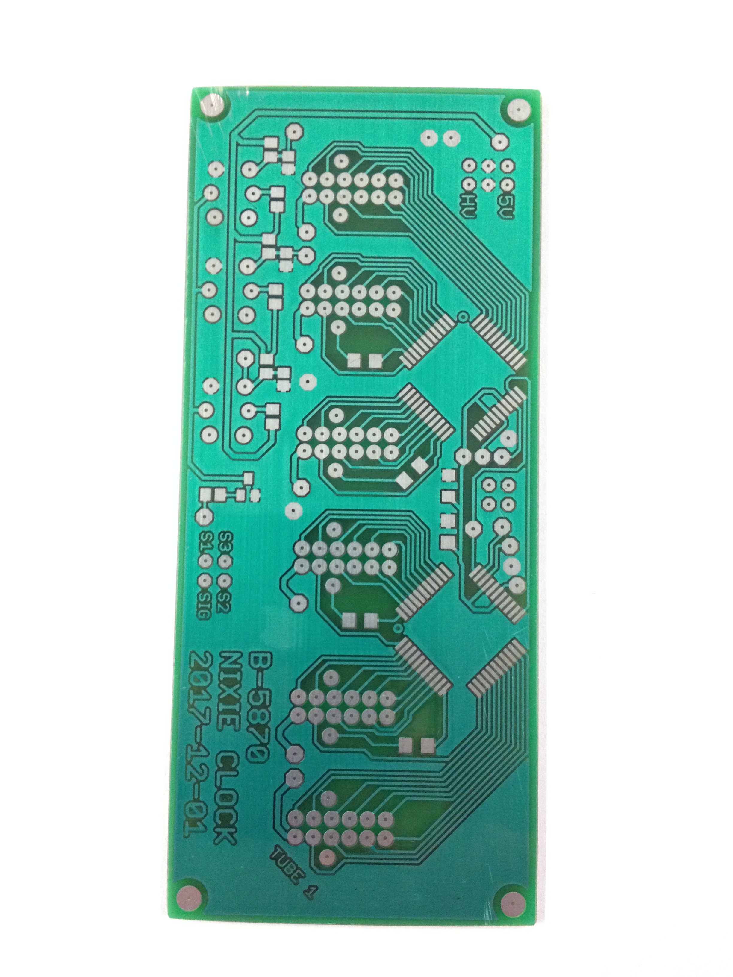
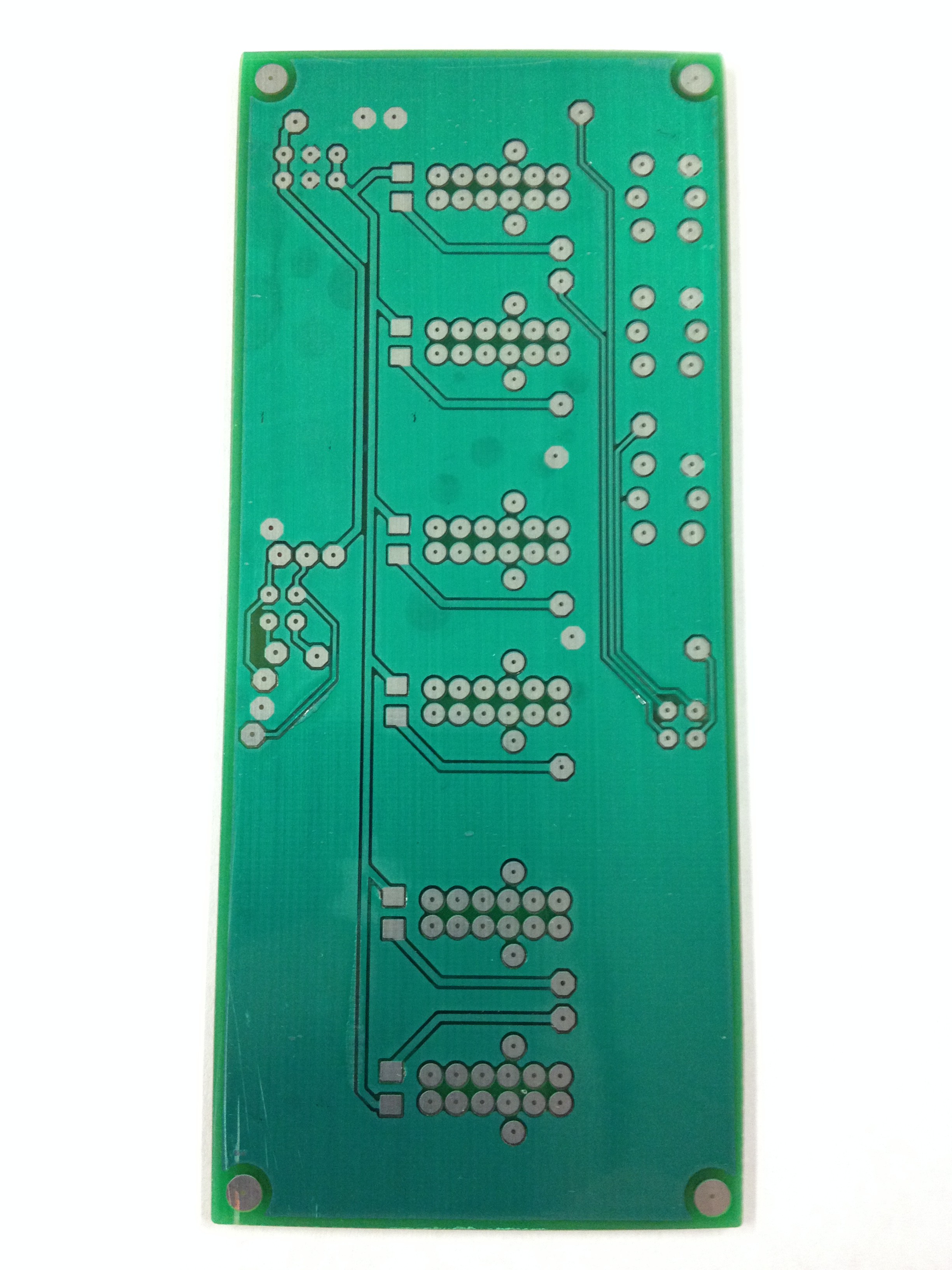
    First was to make the PCB for the tubes.  Here's a few pics of the process:


    Bottom  of the board after etching and tinning.


    Bottom of the board after solder mask applied

    Top of board after solder mask applied

    Bottom of board after cut to size

    Top of board after cut to size

View all 5 project logs

Enjoy this project?

Share

Discussions

JP Gleyzes wrote 04/23/2018 at 17:58 point

Hi,

That's a really nice project.

I enjoy ESP projects and I was trying as well to design my own nixie clock (IN-14 tubes).

This week end I fully designed the pcb using the russian equivalent of 74141 binary to decimal encoder.

I also added mosfets to switch the anodes and allow multiplexing... It's not a nice pcb... a lot of wires and too much complexity !

And I found your design !

When you say : "On this clock I use 3.3V to run the  HV5530s which is way below the recommended voltage (~10-12V) but still within the maximum operating range"

What does it exactly mean ? Do you power the chip with  3.3V ?

Or do you power it at 5V and interface it with the  ESP32 at 3.3V ?

In both cases, does it really work well in all conitions ? Is it reliable ? (I am a lazy man and adding level shilfter is not cool !)

Another question, to help me decide if I change my current design, would you have a sample code to see only the HV5530 part ?

Thanks

JP

  Are you sure? yes | no

myte wrote 04/26/2018 at 11:45 point

hi, thanks for the comment.  the datasheet recommends about 12 volts but also has a section showing absolute maximum values.  3.3V is within these absolute maximum values.  it says stresses outside the maximums can cause damage.  i reasoned that since 3.3V is inside these maximums then it should be OK.  however as with anything it's probably better to operate closer to their recommended values.  so far the clock has worked fine.  I run my HV5530s and ESP32 at 3.3V.

here is some bare bones code I wrote:

http://makerangst.com/nixie-clock-3/5

you should be able to glean from that how to get your tubes working.  the important part is the arrays (tube1[], tube2[].........tube6[]) that list the connections for each display digit of the tubes to the pin numbers of the HV5530 shift registers.  since there are 2 HV5530s then there are values from 1 to 64.

you might also look at the HV5523 which operates between 4.5V and 5.5V (you'd need to level shift of course). 

  Are you sure? yes | no

JP Gleyzes wrote 04/27/2018 at 11:07 point

Hi,

Thank you for your kind and clear answer (and for the code example).

BTW, it's really simple to drive this HV5530 chip ! (clever code with the look up tables)

I will try as you did : "direct drive from 3.3V"

You could as well have powered the HV5530 with 5V and just use the ESP32 interface @3.3V ? Don't you thing so ?

  Are you sure? yes | no

Weix wrote 03/01/2018 at 09:21 point

very nice project!! i´d really like to build one too! Are you so friendly and share your arduinocode with us? :)

i have some 74hc595 shiftregister ICs lying around.. is it eventually possible to drive with this IC the numbers of the tubes?

  Are you sure? yes | no

myte wrote 03/03/2018 at 11:35 point

You'd need components that can handle the higher voltages necessary to drive nixie tubes.  You could direct drive each tube with K155ID1 IC's (readily available on ebay) and use your shift registers to control those.  You could reduce the number of drivers needed by multiplexing.  if you google a bit you'll find a lot of examples about multiplexing in such a way.  You'd need some more transistors and resistors though (again look for those examples).

For this particular clock I used HV5530s which turn out to be very simple to use (you can also dim the tubes by using the blanking pin on the chip).  They are basically shift registers that can handle the higher voltage so all you need to do is hook up each pin of your nixies to a pin on a  HV5530.  On this clock I use 3.3V to run the  HV5530s which is way below the recommended voltage (~10-12V) but still within the maximum operating range.  This could be a concern to you so you might be better off with variants that operate at lower voltages.

As for arduino code, I link out to an example of some bare bones code I wrote.  The code you'd need would vary based on your approach to driving the tubes. 

  Are you sure? yes | no

Weix wrote 03/04/2018 at 18:13 point

Hey myte! Thank you! I already supposed it that i have to take a shift register which can handle higher voltages. But isn´t it possible to dim the tubes with all shift registers... you only have to turn it on and off fast enough, also without blanking-pin??? at the moment i don´t know how to drive the tubes .. there are some DIY-Kits at ebay but they all use arduino unos and megas ... so i thought i buy such kit  which has some HV5812WG ICs built in ( 20-bit CMOS shift register, data latches and control circuitry with high-voltage MOSFET output) and would control it with an 8266 or ESP32...what do you think about this?

By the way the solution to sync it with an Internet-RTC is very great.

  Are you sure? yes | no

Similar Projects

Does this project spark your interest?

Become a member to follow this project and never miss any updates