Peter Walsh
-
Demo videos!
05/26/2015 at 00:04 • 0 commentsSummary
1) The power driver board works
2) The control board works
3) The basic control software works
4) I can levitate small bits of paper
A video demo of ultrasonic levitation showing off the system is below.
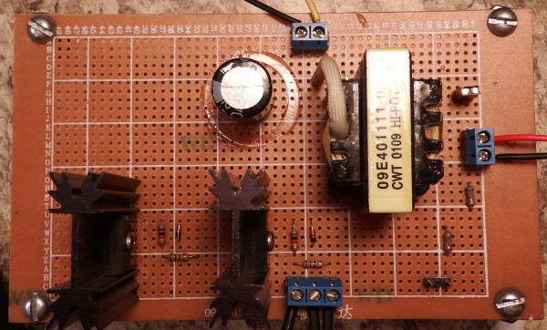
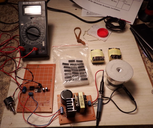
The power driver board is soldered!
For my best shot at the next interim prize, I need to show something soldered, and also have a circuit schematic.
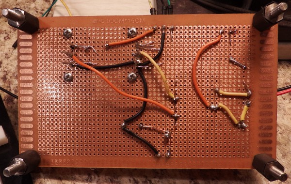
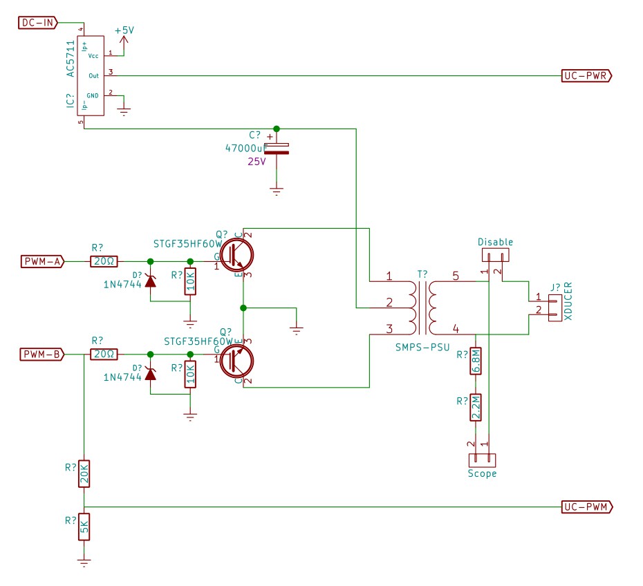
Here's the driver board, and here's the back of the driver board, and here's the schematic. Note the back: it's soldered!
![]()
![]()
![]()
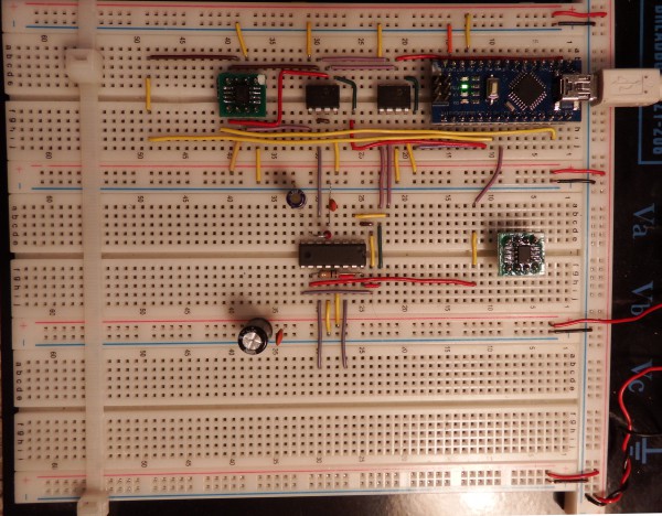
The control board is... not soldered!
I use protoboards when possible - it's easier to tinker with things and fix problems. The driver board handles a lot of power and voltage, so I soldered that, but the control board... it's not soldered. I mounted ICs on carrier boards though, and *theyre* soldered. That counts, right?
Right now I only have direct control - no feedback. This means that I can set the PWM and frequency, but there's no feedback keeping things at the setpoints. That software hasn't been written yet.
Here's the control board, and here's the schematic. Note the components on carrier boards - they're soldered!
![]()
![]()
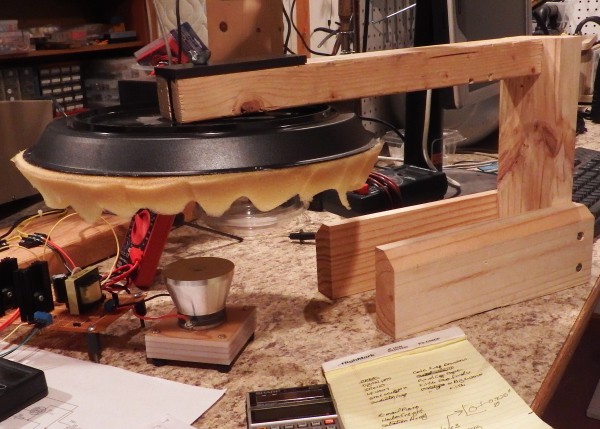
And... the system works!
Mike Harrison built an ultrasonic levitation system which was featured on Hackaday awhile back, so for fun I decided to see if I could reproduce his results. After a few minutes of tinkering, I was able to levitate a small piece of tissue.
The transducer generates plane waves, which are reflected from the aluminum plate over top. The height of the transducer is adjusted so that the distance to the plate is some multiple of half the wavelength.
The result is a standing wave with nodes and anti-nodes, which are seen as "steps" as the tissue paper is played up and down.
I video'd a quick tour of my system, and the levitation results. (Note to self: use better lighting next time.)
A note on Philosophy
People keep asking me why I don't "just go buy stuff" for the project - it would make development *so* much easier.
Usually it's when they hear that I'm casting the aluminum horn. "Just order round stock from McMaster Carr, then you know what alloy you have, you don't have to worry about bubbles, and this-or-that other issue that I've just now thought of. It'd be so much easier..."
The purpose of the project is to put ultrasonic tools in the hands of hackers, and this year's prize is to change the world, so I'm thinking globally.
A 2.75" piece of round stock from McMaster Carr costs about $50. While that may not seem like much as an individual purchase, you can't have many $50 purchases in a project before it starts to get out of reach. The project already requires a $50 transducer from eBay, and I don't want to compound the costs.
Also, I'm regarding people across the world who might not have access to McMaster Carr. African nations, Cuba, maybe some Eastern European places don't have UPS delivery from the US, but might have access to sand, a junked car, an iron pot, and a bonfire.
So I'm structuring the project to reuse common materials as much as possible. If you can find 2 ATX power supplies, a laptop, and an arduino, you can purchase a transducer for $50 and build the rest for under $50.
If you're good at scrounging, you might do it for less: power transistors and heat sinks are in old power supplies, and I've seen the digital pots in CDRom drives. You might also be able to find pot ICs on a motherboard or old sound card.
All the info needed for the project will be available on GitHub: schematics, software, instructions, and where to get materials. Look for it in about 6 months, once the Hackaday prize contest winds down and the development is complete.
User supplied display
I had originally thought to build a system with an embedded display and control buttons, but thinking it through I now believe a serial interface is more useful.
Displays come and go faster than Lada Gaga's wardrobe. In five years, I don't want the project to languish because people can't find the specific graphics display needed by the software, and I don't want software versions for different hardware either. Laptops and PCs will be available long into the future, and eliminating that section simplifies the project.
Also, laptop control means the user can write programs to run the system in ways specific to his needs. With commands such as start/stop/set power/set frequency/set timer available on the serial port, it's not hard to build a scripting system based on Perl or Python to control the system.
Embedded Arduino Nano
For even more simplicity, I'm using an embedded Arduino Nano as a component.
A PCB taking an Atmega chip and associated hardware isn't terribly difficult to design and would reduce the costs a *little*, but it's really hard to beat a $2.18 Nano board from eBay. Using the Nano as a component eliminates a lot of tricky soldering, it's known to work, a hacker is more likely to have one on-hand (fewer parts to order), and it can even be socketed so you can remove it and use it for other projects.
Additionally, I'm discovering that much of the circuitry can be done in software, such as power control and calibration. This makes the control board even simpler to build, It eliminates adjustment pots, the end user doesn't need a scope or DVM for tuning, and so forth.
All things considered, for the PCB I'm just going to throw in a Nano and be done with it. Maybe have pinouts for either a Nano or a regular Arduino, so the user can just populate whichever one they have on hand.
-
Status for May 20
05/18/2015 at 22:42 • 0 commentsSummary
1) Power supply design is coming along
2) Final design will require an embedded Arduino Nano
3) Final design will use a laptop (or desktop) as display
Random Status
A lot of little things are happening with the project but nothing of special note, so I won't post this to the feed.
My DigiKey order came in, I'm working up the various device interface software, nothing exceptional.
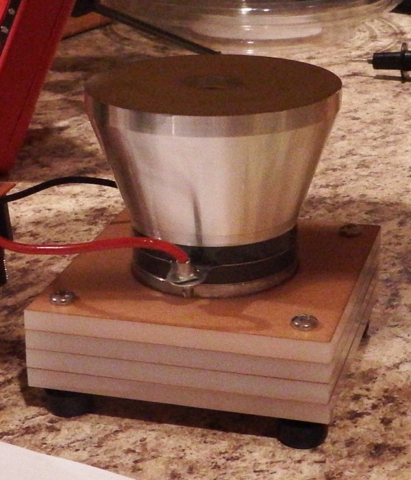
I'm looking into generating Hydrogen on a small scale, and collecting plumbing for the experimental setup.
I've resolved the safety issue using a lasercut holder for the transducer with rubber feet so it doesn't skitter across the table when energized, and a sculpted-foam parasol to catch the ultrasonic energy. (Which looks vaguely like to the starship enterprise.)
![]()
![]()
-
Status for May 14
05/14/2015 at 06:29 • 0 commentsSummary
1) The new driver board works
2) An ATX supply makes a good DC supply for the driver
3) An ATX SMPS transformer can drive an ultrasonic transducer
4) I've ordered parts from DigiKey
5) My ears hurt, and I don't know why...
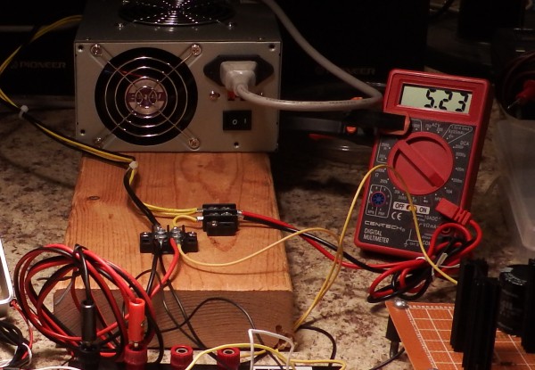
ATX supply makes a good DC supply
I'm using a discarded ATX supply as the DC supply for the ultrasonic driver board. With 12 volts at 15 amps, the system can supply 180 watts of drive power to the transducer circuit. The biggest transducer I can find on eBay is 120 watts, so the range is good.
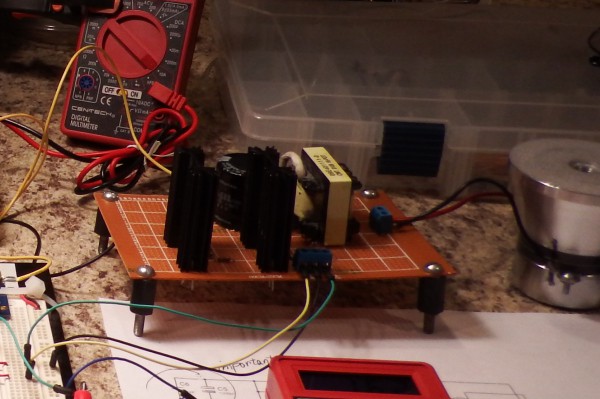
I mounted the supply on a board with decent bus connections and a current monitor tap. Harbor Freight was giving out free DVMs at one point, so I got a bunch and use them as embedded current/voltage monitors. The system is pushing 5.23 amps in the image below.
![]()
The new driver board works
The driver board, which uses an SMPS transformer scavenged from a different ATX supply, works. The transformer generates enough voltage to drive quite a bit of power through the transducer at resonance - I've had the system "accidentally" up to 17 amps, which is 200 watts, or double the rated transducer output.
It's a bit noisy, so I have to figure out some way of filtering. Also, I have to add some circuit protections such as zeners on the driver gates and such. Maybe a bypass cap on the gates as well.
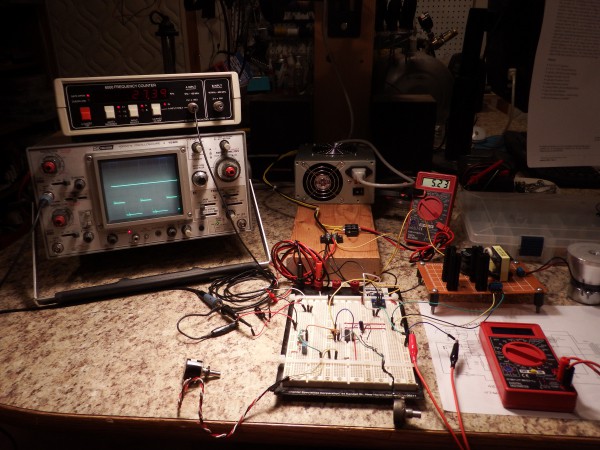
The power driver is the perfboard sitting in front of the current meter (yellow-stripe transformer).
![]()
SMPS is working, manually
The SMPS circuit is working manually; meaning, I can adjust the frequency and duty cycle using two pots. I'm waiting on some parts from DigiKey, then I'll be able to hook the system up to an Arduino to monitor and control frequency and power.
![]()
My ears are still ringing
While attempting to get a picture of the system pushing 10 amps (120 watts), the system accidentally ran up to 17 amps for a few moments.
Despite immediately shutting down the system, the transducer managed to walk across the table (no mean feat at 28kHz) and my head has been ringing ever since. And I never heard a thing.
Yikes!
I suppose this is the ultrasonic version of playing with lasers, I'll have to come up with some type of safety gear to protect myself. Maybe earplugs?
Have to do some research...
-
Status update May 10
05/10/2015 at 08:11 • 1 commentA quick interlude
M.Bindhammer's Hackaday Prize project proposes making hand-held chemical reactors for the synthesis of Aspirin.
Whether making Aspirin locally is cost-effective or not, I like the idea of hand-held chemical reactors that anyone can make. If the "proof of concept" can be made with Aspirin, then his ideas may lead to a wide array of hand-held chemical processing components.
We have a laser cutter at my space, so I offered to make and send him some prototypes. The results are below.
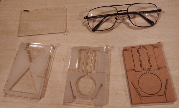
The first one on the left is a vacuum filtration system. You put a section of filter in the horizontal slot at the top, then connect a vacuum pump to the passage leading from the side. (Doesn't photograph well - see his project page for info.)
The second one (middle) looks a lot like a reflux distillation system, which would be totally awesome if that's what it is & it can be made to work. The third one (right) is how the plastic comes from the laser: sticky paper protecting the surface, and without the intervening blocks removed.
These are comprised of 3 acrylic pieces: a clear face and back plate (upper left) with 0.3" ivory acrylic in between. To assemble, you line up the middles on the plates, then dribble a little methylene chloride (MEC) at the interfaces using a syringe. MEC, an acrylic solvent, gets soaked up by capillary action and dissolves some of the acrylic. Then it evaporates, leaving the acrylic pieces welded together.
If I understand his process, acrylic *should* tolerate the temperatures he needs for his synthesis, and should be immune to the reagents. (And if not, it's still a good material for a physical prototype.)
Check out his Hackaday Prize project for more info. His ideas hold a lot of promise.
![]()
Power supply development is proceeding apace
I figured out a lot about computer PSU transformers, and now have a good idea of which ones are good to use for this application; meaning, I can now write a build procedure that describes to others what to look for when scrounging for this part. If everything holds as I think it should, anyone who wants to build an ultrasonic supply can use one PSU for power and cannibalize another one for this singular-and-difficult-to-find part.
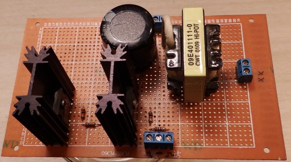
I got my UC3525 SMPS controllers running on a breadboard, and made a new power control board, shown below. Testing starts tomorrow.
![]()
-
Status
05/06/2015 at 03:39 • 0 commentsAh, Spring. In the spring a young man's fancy lightly turns to thoughts of...
Eeek! More than a third of the Hackaday prize time has passed! Have to make some progress real soon or curtail the project goals!
A status update follows.
![]()
The lathe at my hackerspace is still offline, so I haven't been able to do any more horn tuning. Next week 'fer sure.
I cast two new horns by way of a casting demo at the space - a 2nd horn for my small (50 Watt) transducer, and one for the large (100 Watt) transducer. I've got pics and intend to make a full blog post (two, actually) with instructions, tips and tricks, etc.
(ProTip: Don't run the kiln from an extension cord, at the hackerspace, as a casting demo. Kilns and extension cords don't mix. Now I know.)
After the [abortive] demo, one of the members offered me a piece of round-stock aluminum that's just the right diameter to make the bigger horn. That's about $30 of stock in one piece right there. Thanks, Adam!
And apropos of nothing, this is why I cast horns instead of, for example, ordering stock from McMaster Carr. I'm not Tony Stark.
(But to be fair, Stark himself cast his first arc reactor, so he too uses this method.)
The PWM controller chips (ziplock bag in middle) have just now arrived, I haven't had a chance to breadboard any.![]()
My frequency generator has poor resolution at 28KHz, so I made up a 555-timer squarewave generator (leftmost board) with a 10-turn pot. The pot sits in the middle of the frequency range of the transducer, so there's a lot of resolution with little drift.
I also breadboarded a SMPS transformer from a computer PSU and a drive transistor (lower-middle board). I also pulled two more transformers for comparison (upper right).
The good news is that the transformer generates 200 volts AC from a 12 volt supply!
This is about the right voltage to run 100 watt transducers off-resonance, which means that anyone who wants to make the circuit can get the only expensive-and-hard-to-find part from a junked computer.
It also means said hacker can run the circuit from a 10-amp 12-volt supply - in all likelihood an old computer PSU will suffice.
(I think. Time will tell if this is right.)
But this also means I can't show any progress. The 200 volts would push too much power through the transducer, so I have to get a PWM circuit running that will control power before I can show anything working. Right now I'm limiting power by crowbar'ing a supply that doesn't have overcurrent protection, and that's not an optimal solution.
THANK YOU
to everyone who signed up to follow the project & gave out skulls!
Getting the E-mail notices from followers/skulls makes me happy, and I save every one. (Not making that up.)
-
New power supply design
04/29/2015 at 18:05 • 7 commentsSummary
I'm designing a hobbyist power supply for ultrasonic transducers in the 100 watt range, with these goals:
1) Automatic resonance seeking
2) Variable power output
3) Microcontroller measurement and control
4) Generally bullet-proof and safe
Circuit and an explanation are posted below.
More Difficulties
Someone at my hackerspace took the lathe offline and didn't tell anyone, so I'm blocked from making transducer horns for the moment. They won't let me strangle him, but to be fair, they won't let anyone else strangle him either.
So I'm concentrating on a new power supply circuit for hobbyists which won't burn out and has some useful features.
NOTE: This is very much a work in progress. I'm waiting on some parts, I haven't bread-boarded and tested, and it doesn't make sense to capture a circuit before you know it will work.
Also, I'm not an electronics engineer and this puts me out of my comfort zone, so if you see something fundamentally wrong with the circuit, please let me know.
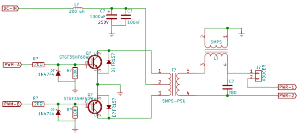
Switcher
![]()
Compare with the supply from eBay.
The switcher uses the same standard totem-pole configuration, but with a proper DC supply instead of cheaply-rectified AC mains.
The user must supply their own 120 watt DC supply in the 12V - 80V range, but these are *common*. A 30 volt 10 amp supply goes for $10 on eBay: it's safe, reliable, and cheap. You can even put two of them in series for higher voltages! (I've never done this, but I'm told it will work.) Switch mode supplies have isolated outputs, so it's OK to connect the outputs in series.
I'd *like* a system that would work from 12V, thus driven from a computer PSU (those are *really* common), but this depends on the specs of the SMPS transformer. I'll know more a bit later in the project.
The transistors are a wee bit overspec for the application (35A, 600V). The difference between "50% more than needed" and "insanely overpowered" is a couple of dollars (like, $2), and I want this to be bullet proof. The transistors are typically what burns out if the user makes a mistake, and we can let the fuse do its 'goddam job for once.
On the output side, the capacitor and inductor form a low-pass filter that turns the square-wave into a sine wave.
The mathematical formula for a square wave is:
Where "A" is the square wave amplitude, and "f" is the frequency.
If the low-pass filter has a cutoff somewhere between f and 3f, the higher frequencies will be suppressed, presenting only the fundamental to the transducer. As a bonus, the result is slightly higher voltage than the original square wave due to the 4/pi term.
The capacitor is TBD because the inductor is a SMPS transformer and I don't know what that inductance is yet. Needs to be high voltage with low ESR - probably polypropylene.
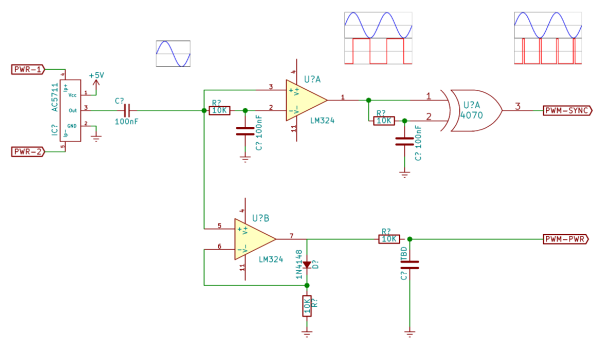
Synchronization and Power measurement
![]()
In addition to the transducer, the output goes through an Allegro hall-effect current sensor via PWR-1 and PWR-2, from the switcher.
The Allegro chip generates a voltage proportional to the current through the transducer. It has low resistance (a few mΩ), 2KV isolation, and an 80kHz bandwidth. This one chip solves a whole lot of issues.
The signal from the Allegro chip becomes two outputs: a voltage proportional to current, and a frequency synchronous pulse train.
The lower path routes the sin wave through an active rectifier, followed by an RC integrator. The output is a DC voltage proportional to the current through the transducer, which is delivered as feedback to the PWM controller.
The upper path requires a bit of explanation. The SG2535 controller driving the switcher has a "synchronize" input that can be used to slave the internal oscillator to an external clock. The slave signal is a pulse that switches the oscillator from its charge cycle to it's discharge cycle, so to synchronize the chip to the transducer we need to generate pulses at the *peaks* of the sine wave signal. That's what the top path does.
Referring to the signal images in the circuit, the sine wave is presented to both inputs of an LM339 comparator (typo'ed as LM324) with one input delayed by an RC constant. Since the negative input is delayed, a rising signal will result in a positive output, and a falling signal becomes a negative output. The result is a square wave which is 90 degrees off from the original signal.
The square wave is presented to both inputs of an XOR gate, and once again one side is delayed by an RC constant. This results in a series of pulses at each transition of the square wave - at twice the original frequency.
...which is what the SG2535 wants to see for synchronization.
(If I have interpreted the datasheet correctly. There's *very* little information available about this chip, and as far as I can tell no example circuits on the net use the synchronization feature. And if they did, they would be slaving one SG chip to another, without noting what signal that is.)
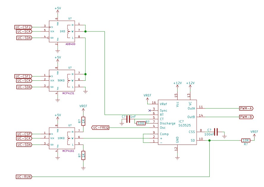
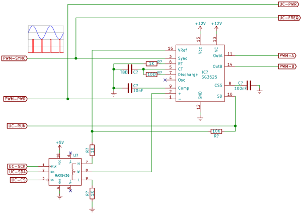
PWM control
![]()
The power and synchronization are presented to a UC3525 PWM management chip, which controls the switcher (first image) via PWM-A and PWM-B.
The UC3525 has an onboard 5.1 volt reference, which runs through a digital potentiometer controlled by the microcontroller. The voltage chosen by the micro is compared to the current signal from the transducer, and used to adjust the PWM width. As the transducer draws more current, the voltage goes up and the PWM controller reduces the pulse width to compensate.
Negative feedback keeps the system fixed at a power level calculated by the micro, and the sync input keeps the frequency locked to the transducer/system resonant frequency. From the point of view of the micro, it's "set and forget".
Labels "UC-xxx" represent connections to or from the microcontroller. For example, the micro can turn the output on or off using the SD ("shutdown") input to the switcher.
Possible issues
My biggest issue ATM is finding vendors and specs for SMPS power transformers, as found in computer power supplies. So far as I can tell, no standard vendor sells them (DigiKey, Farnell, Mouser, Coilcraft, et al). Lots and lots of sellers on AliBaba, but no one has specs.
I'd *like* to say "pull two transformers from old computer PSUs", because that would be an easy source for the hobbyist, but I suspect there's a lot of variation and being able to tell which ones are good to use is not a casual skill.
I'd *also* like to point to a list of component vendors, in case the hobbyist just wants to buy the parts and put it together, and maybe sell a parts kit or something. That's hard without a specific vendor and proper specs.
If anyone knows where to get SMPS transformers cheaply (meaning: not $50 each from a specialty brand) please let me know.
If anyone sees a flaw in the logic, also please let me know.
-
Analysis of the eBay ultrasonic power supply
04/26/2015 at 22:10 • 6 commentsSummary
1) The ultrasonic transducer power supply boards found on eBay are, um... unsuited for hacker use.
2) Despite being careful, I managed to burn one out.
3) Apparently, no one else has been able to get these to work, either.
4) I'm a total coward when it comes to high-voltage measurements.
Hackaday Fail
For the project, I had originally planned to build and describe two types of ultrasonic experiment kits: a "simple" unit based on an eBay power supply board with a timed relay, which would be simple to purchase and assemble, and a "designed" supply with adjustable power and microprocessor control.
I've since played around with the ultrasonic power supply board that came with my transducer, and have concluded that these are pretty-well useless for hacker purposes. Additionally, I managed to burn one out despite being careful.
My explanation of why these boards burn out so easily is below, after some background info about tuned circuits.
(NB: Apologies for the large images - the http://hackaday.io system doesn't save the image size properly. It looks good while editing, but after posting the images go back to "full size.")
![]()
Powering a resonant circuit
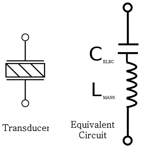
As mentioned in a previous post, an ultrasonic transducer is effectively a series resonant LC circuit: the piezo plate electrodes form a capacitor, and the resonating mass acts as an inductance.
![]()
![]()
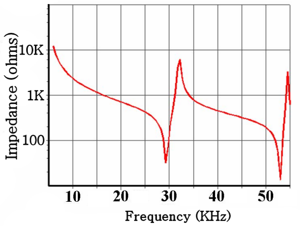
Since the transducer is an LC circuit, it presents different impedances to the driving circuit at different frequencies. At its resonant frequency (28 KHz), it will appear to be a 25 ohm load, and when driven off-resonance, it will look like 1000. And driving the device at an intermediate frequency will result in an impedance omewhere between the extremes.
(The high peaks in the plot are the parallel resonant modes, which should be avoided. Most of the off-resonance areas are about 1000 ohms.)
The eBay transducers are rated at 100 watts, so the next question is: "What level of drive voltage is needed to push 100 watts through the device?"
Power is voltage squared divided by the resistance, which in this case is the impedance to the AC driving voltage, so the needed voltage depends on the driving frequency:
Tuned horns and cleaning baths
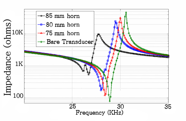
![]()
Most ultrasonic applications use a metal horn attached to the transducer to focus the energy into a small area, depending on the application. The horn vibrates at its own resonant frequency, so the resonant frequency of the complete system (transducer+horn) is a melding of the two. Typically, one makes the horn extra long and "trims" it to match the transducer resonance.
![]()
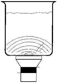
An ultrasonic cleaner connects the transducer directly to a metal bath chamber where the ultrasonic energy gets bounced around a lot.
1) The chamber is square(ish), with rounded corners
2) You don't know ahead of time how much liquid is in the chamber
3) You don't know the density of the liquid (it might not be pure water)
4) You don't know what or how many things are in the water to be cleaned.
Because of this, the cleaner bath will never be in sharp resonance as one would get with a tuned horn. The ultrasonic cleaning system should present a high impedance to the driving circuit in all cases.
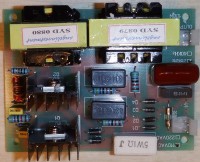
The eBay ultrasonic transducer driver explained
![]()
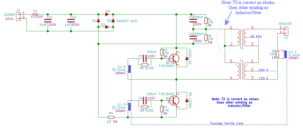
Here's the full schematic of the eBay driver board.
The 120 volt input is rectified (poorly) into 160 volts, then split into a balanced +/- 80 volts by C3/C4. One end of the T1 primary is held to the common midpoint, while Q1 and Q2 alternately switch the other end high (+80 volts) and low (-80 volts). The secondary of T1 amplifies this voltage, while T2 acts as a rude filter for the output waveform. Note that T2 is only used as an inductor - the primary is shorted and grounded to keep it from generating any voltage.
The transducer oscillations are picked up by L1-1 and delivered to Q1 and Q2 via L1-3 and L1-2. As Q1 powers up the transducer, feedback from L1 will eventually turn it off and Q2 on to power the transducer in the other direction. As Q2 powers up the transducer, feedback from L1 eventually turns *it* off and Q1 turns on again.
The output voltage at T1 is about 4x the input voltage from the rectifier/splitter (as gingerly measured using a variac). At full AC voltage, 80 volts becomes 320 volts at the output, which is about right for an off-resonance system.
I believe this is a variation of a Royer oscillator. The system will find and keep the resonant frequency of the "transducer plus system", whatever that may be.
Problems with the eBay circuit
1) It burns out easily
The biggest issue with the eBay circuit is that it has a tendency to burn out.
Referring to the calculations above, the circuit generates voltage appropriate for a fairly high impedance. A bare transducer (nothing attached) will present as a highly tuned circuit with low impedance, drawing some 6x more current than the transistors expect. The transistors burn out within a few seconds (like, three seconds).
(As an aside, this is why ultrasonic cleaner manuals warn about running with little or no fluid. For instance, the Branson ultrasonic cleaner user manual has the ominous: "Do not allow the solution to drop more than 3/8 inch below the operating level line with heat or ultrasonics on. Failure to comply may cause transducer and/or heater damage and will void your warranty.")
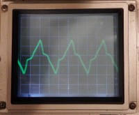
2) The generated waveform is crappy
![]()
The output waveform is nowhere near a sine wave.
Looking at the circuit, note that the AC is rectified, but not smoothed. With no filter capacitors on the supply, the system is switching bouncy AC at 29 KHz through a high-frequency SMPS transformer.
This might be OK for ultrasonic cleaning as it only makes the rubble bounce around more, but it's not good for the home lab.
3) There's no good way to adjust the power
You could probably run the board from a variac while simultaneously measuring the current, but that's a lot of effort. Additionally, if the system goes out of tune for whatever reason (such as the transducer heating up) the power will drop, and if you adjust the power and the system comes *back* into tune you risk burning out your board.
It's a lot of trouble to go to, and you have to keep watching it.
Also, the variac doesn't have much resolution at 1/6 full scale, and it's not clear that the feedback circuit would even work at that low voltage.
4) The circuit is nigh impossible to measure
A scope probe pretty-much anywhere will change the circuit behavior in bad ways.
Parting thoughts
As near as I can tell, no one has posted a YouTube video demonstrating a home-built ultrasonic cleaner. (There are some posts that use motors and orbital sanders, but none that are both home-built and actually ultrasonic.)
Additionally, this link suggests that *no one* has successfully home-built an ultrasonic cleaner. This instructable is the only real home-built ultrasonic cleaner I could find, and he's using a $200 professional board (not the eBay board) *and* he burned one out in the process.
I realize that used cleaners start at around $50 on eBay, but still - affordable 100 watt ultrasonic transducers would seem to have good hacker potential. I'm surprised no one else is using them for projects.
I'm currently designing a power supply based on the 3525 PWM controller. These have a sync input which can be used to slave the device to an external clock. I think the transducer feedback can be used as this input, which would make the system self-resonant.
-
April of the Difficulties
04/14/2015 at 02:49 • 0 commentsI'm a bit further along in the project than the build logs might suggest, and am stalled while I sort out a few issues.
Here's what's going on ATM.
(Give feedback if you don't like these "Peyton Place" type of status updates.)
Transducer resonance isn't acting as expected
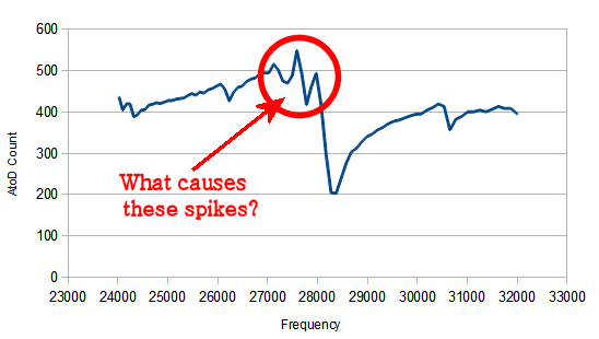
I wrote a program for Arduino hardware to automatically sweep through frequencies and determine the transducer resonance point, and this seems to work as expected.
When I cut/paste data into LibreOffice and plot the results, there's an unaccountable spike in the data right at the resonance point. This is reproducible and not a bug in the program so far as I can tell, and it needs to be addressed in order to get accurate transducer measurements.
I made a list of possible explanations, and am in the process of testing and eliminating each.
1) A bug in the transducer program
2) Arduino hardware not powerful enough or otherwise not suitable for excitation
3) Poorly chosen component values for the interface circuit
4) An artifact of using square waves instead of sine waves to energize the transducer
5) Defective transducer/artifact of the transducer
6) Some other explanation
(NB: The Y-axis scale is in AtoD counts, which is upside down from the normal impedance plot. Maximum AtoD voltage is minimum impedance.)
![]()
Horn is much longer than needed
I used the speed of sound in aluminum to calculate the proper horn length (1/2 wavelength), and then cast and turned down a step horn.
'Turns out, there's two speeds of sound in Aluminum, and I used the wrong one (*sigh*). The 6400 m/s value is the speed of sound in bulk material, but it's 5100 m/s in a cylinder. I have no idea why the speeds would be different for different geometries, but there are definitely two values cited on the 'net depending on which source you use. Looking at Lindsay Wilson's page as a comparison check indicates that my horn 25% too long.
Not a big issue, it only means I have to face off the horn to bring it closer to the required length. I should also shorten the casting form.
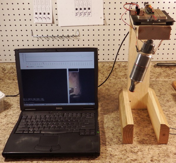
Attaching horn to transducer has no effect
I wrote a program for the PC which triggers the frequency sweep and pops up a chart (like the one shown above) so I don't have to keep cutting/pasting data into LibreOffice to see the results. This means I can take my laptop to the hackerspace and shorten the horn using their lathe, then quickly see what this does to the resonant frequency. Hit uparrow/enter and it automatically triggers the sweep.
(I'll put this program up on GitHub along with everything else.)
![]()
...and come to find that shortening the horn has no effect on the system resonance. Possible explanations:
1) Horn face is not flat, not making good contact with transducer
2) Problem with interface/electronics/program (see above)
3) Defective transducer
4) Other explanation
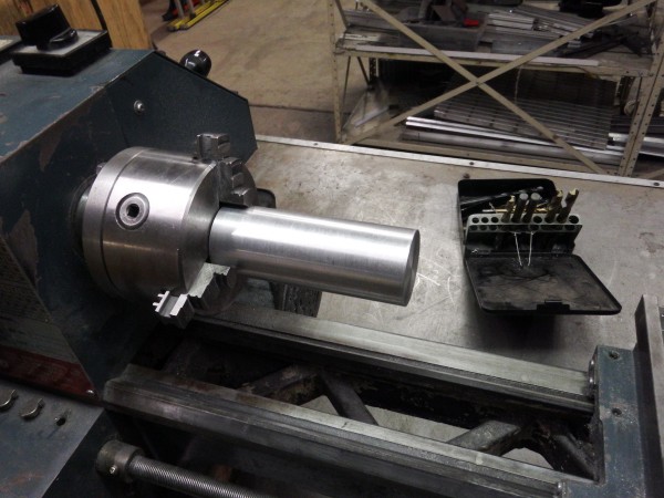
I Need a better way to mount the horn in the lathe
Learning to use the lathe has been a journey of discovery. I can hold the horn by either end in the chuck to face off a section (for tuning), but in doing so there's nothing holding the faced end. I can't use a tailstock center because it gets in the way of the facing operation. I can't mount the horn further into the headstock because it's too big for the hole in the middle. The steady rest badly(!) chews up the surface.
Also, the lathe 3-jaw chuck bites into the end of the horn. This is not an issue for the horn, but it'd be nice to be able to make professional-looking turned items.
So far I've been getting by on guts and liquor, but I really need a better solution. Possible solutions include:
1) Cut out wooden vice jaws and clamp the horn in the/use the Bridgeport mill for facing with a fly cutter.
2) Make/get a steady rest that uses bearings instead of brass fingers
3) Hold the horn by the small end in my hexagonal collet form
4) Find a bigger lathe
The image below illustrates the problem using the 1:1 step horn, which doesn't have a skinny end. For the step horn I have to clamp the skinny end in the chuck and face the fat end hanging out in empty space. The horn doesn't fit any further into the chuck.
![]()
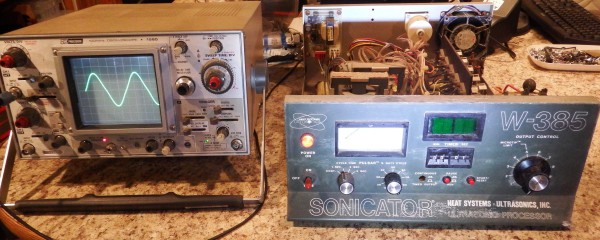
Power supply from eBay is all busted up
The power supply I ordered from eBay is a bit... pre-owned.
Pretty much all of the front panel controls are busted in some way or another: the power switch is broken permanently in the "on" position, two of the latching PB switches are jammed or broken, and the digital display doesn't light up. The connectors in the back are rusted, and the outsides are covered with a fine white powder, which I'm privately hoping doesn't turn out to be poisonous or carcinogenic. The insides show signs of severe rusting, as if the unit has been outside for several months.
The good news is that despite all this, the system seems to work. It fires right up and generates a perfect sine wave. With the power control set to minimum the output sits at 200 volts. Yow!
![]()
-
Reverse engineering a cheap eBay ultrasonic power supply
04/10/2015 at 20:22 • 19 commentsTL;DR
I purchased and reverse engineered a cheap eBay ultrasonic power supply, to see if it held any value for the hobbyist.
This first post explains the process of reverse engineering the (or any) board.
A subsequent post will discuss the specifics of this board.
NB: Can anyone tell me what R4 (1 ohm, 5 watt) does in the schematic below?
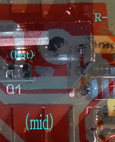
How to reverse engineer a simple PCB
Dave Jones posted a great video (from his blog) showing how to reverse engineer a PCB. He prints and overlays transparencies of the board top and bottom, so that he can visually align the traces with the components.
I did essentially the same thing, but within a paint program - eliminating the need for physical copies. This has some advantages over his method (zoom, annotation, and contrast adjustment), but some disadvantages as well (small visual aperture).
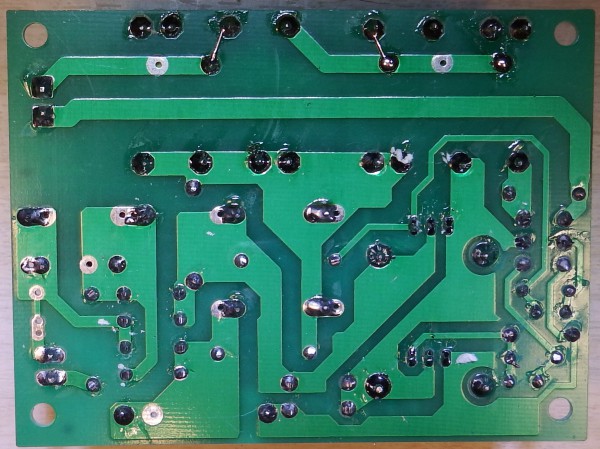
Step 1: Take a picture of the top and bottom of the PCB
![]()
![]()
Step 2 Flip and flood
Flip the trace image left-for-right, and flood-fill the copper traces with a high-contrast color. Use the pen/brush tool to touch up areas that didn't fill properly (ie - the shiny, reflective bit in the image above).
![]()
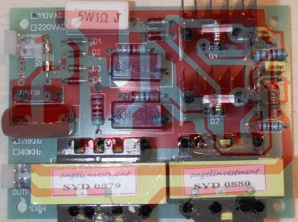
Step 3: Make a sandwich image
Compose a 3-layer image with the components image on top, the traces in the middle, and a white bottom layer. Set the bottom (white) layer opacity to 100%, and adjust the opacity of the trace and component layers to give a nice X-ray view of the board.
(This will be specific to your eye sensitivity and the characteristics of your display, so adjust to taste. For my setup, the best settings seem to be White: 100%, Trace 100%, Components: 78%.)
Rotate and adjust the trace layer so that the holes in the trace layer line up with the components.
![PCB X-ray view]()
![]()
Step 4: Zoom and annotate
The image can be zoomed and annotated as needed. Also, sections and components can be erased once deciphered. (I found this particularly useful - certain sections are "distracting", and blocking them helps me concentrate on other sections.)
![]()
The results: a shiny, new annotated schematic, ready for the surgeon's table:
![]()
A high-resolution version of this (pdf and svg) will be available on GitHub presently, as well as the KiCad schematic.
Discussion of this specific circuit will be in a subsequent log.
-
Back of the envelope calculation
04/05/2015 at 00:49 • 0 commentsImproving the Bosch-Haber process is a challenging problem, so before I embark on any particular action it's probably a good idea to see if there's any chance of succeeding.
As the saying goes, four hours in the lab will save you an hour in the library...
NB: I am not actually a chem major, so if you see an error in the analysis, please let me know!
Where to find information
Several researchers have looked into ultrasonic nitrogen fixation. For the technical reader, "Sonochemical Fixation of Nitrogen" by Supeno is a good starting point. The paper reviews the previous research and explains the various processes, including cavitation, chemical reactions, solubility, kinematics, and so on.
If you want more information on the problem I'm trying to solve, that's a good place to start.
For a good overview of the ways nitrogen may be fixed, try "Fixation Of Atmospheric Nitrogen" by Frank Ernst. Published in 1928, it gives a little of the history of nitrate usage, and explains in detail the various methods of producing it.
Chapter 1 (history) has an interesting take on WWI:
It is quite generally believed that Germany declared war in 1914 only after assuring herself that she had a suitable source of fixed nitrogen within her own borders. The rate of consumption of nitrogen in explosives during this war was undoubtedly far beyond the expectations of any individual or nation. In order to meet this demand it was necessary, even with the enormous expansion of the rather young atmospheric nitrogen fixation industry, to stint agriculture. How great an effect this had on the eventual result is rather difficult to appraise, but there Is no doubt that the people of several of the warring nations suffered materially and still show the effects of malnutrition.
If you just want the basics of the Bosch-Haber process, this link is pretty good.
For more detail on why ammonia fixation plants are so expensive, check out "Chemical Reactor Design For Process Plants, Vol II" by Howard F. Rase. It's an Ammonia fixation plant case study, and has all the gory details. Not for the faint of heart, guaranteed to make your head spin.
Energy required for Bosch-Haber
According to this link, Nitrogen from the Bosch-Haber process requires 34.5 Gigajoules per metric ton (mt) of nitrogen produced. I can't tell if that's nitrogen produced or ammonia produced, but it doesn't matter because they weigh about the same and this calculation is only approximate.
So Bosch-Haber requires over half a million joules to create one mole of ammonia.
To put this in perspective, 1 mole of ammonia weighs 17 grams, and that many joules will run a 100 watt incandescent bulb for over 90 minutes. Yow.
And this for a chemical reaction that gives off energy in the process. Quite a lot of it, actually:
To put that in perspective, this is about a third of the energy you would get from burning the same mass of wood.
The reason the reaction doesn't easily happen - the reason we can't simply ignite the gases like so much paper - has to do with the interplay of the activation energy (breaking the N2 apart) and the entropy. When you heat the gases enough to start the reaction, the reaction is no longer favored and the reverse reaction happens instead. Ammonia breaks down into nitrogen.
This is actually a good thing, otherwise a lightning strike would ignite the atmosphere, oxidizing all the nitrogen and turning rain into nitric acid.
I'll post a more complete explanation in a future log. For now, the target to beat appears to be about half a million joules per mole.
Energy required for sonication
According to another Supeno paper, the maximum rate of ammonia produced was 4 nmol/min/W. Converting to Joules and moles:
Target for this project
Comparing the Bosch and sonification energies:
So for purposes of this project, I need to improve the efficiency of sonification by a factor of about 25,000.
This isn't quite as bad as it looks.
For one thing, I think I can get a factor of 10 (and maybe as much as 100) using a highly tuned transducer horn. It wasn't clear from Supeno's paper, but from his description it looks like he's using a water bath, similar to an ultrasonic cleaner, and he makes no mention of tuning the chamber or transducer. Even if he's running the system at resonance, he may not be running the transducer at resonance, and this will reduce his efficiency.
There's also an interesting quote from his abstract:
The decrease in the rate with bulk temperature suggests that kinetics, rather than thermodynamics, is the limiting condition for sonochemical synthesis of ammonia.
There seems to be no chemical or physical reason why sonification can't work, and the comment above seems to indicate that changes in the experimental setup (geometry, reaction profile, and such) might affect the efficiency.
I'm quite looking forward to trying.
Improve the Haber process
See if ultrasonic cavitation can be used to fixate atmospheric Nitrogen less expensively than the Haber process.