 M. Bindhammer
-
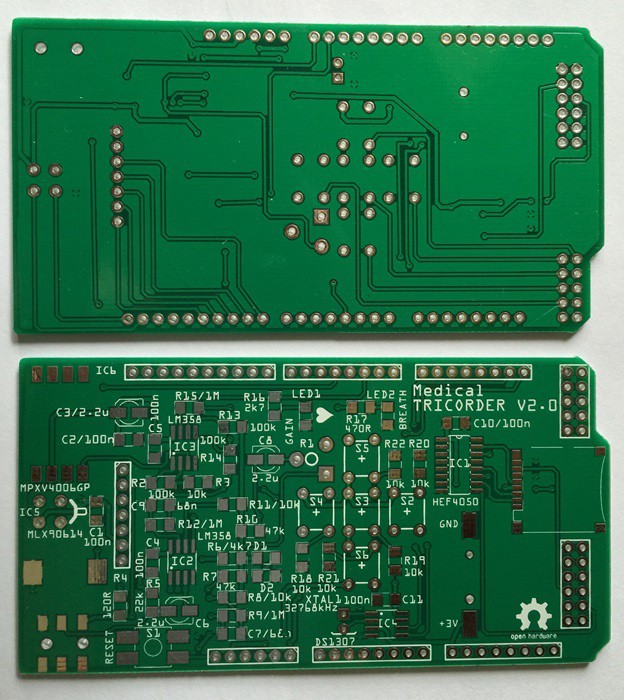
1Step 1Send the Gerber files to your favorite fab house. Any PCB manufacturer will accept Gerber formatted design files. Order at least two or three pieces in case you mess one PCB up.
![]()
-
2Step 2
Populate the board. You should have some experience with SMD soldering. If not I suggest this tutorial. Start with the micro SD card socket, continue with the IC's, discrete SMD components like resistors, capacitors, diodes and LED's, then solder the electrolytic capacitors, the MPXV4006GP, the SMD piezo buzzer, the audio jack, the SMD RESET push-button and the coin cell battery holder. Some components like the LED's have no markings on the package to indicate polarity so you'll need to take care when placing them.
![]()
Thru-hole components like the MLX90614, the female pin header for the OLED, the trimmer, the mini push-buttons and the crystal for the RTC will be soldered at the end. Use a piece of heat shrink to insulate the body of the crystal.
Next, place the male pin headers into the Arduino Mega board. This will make sure that the headers are perfectly lined up. Make sure the Arduino Mega is not powered or plugged in to USB! Place the medical tricorder shield on top of the Arduino Mega, making sure that all the headers line up nicely. Solder in each pin of the headers.
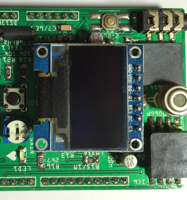
Next, start by placing a 7-pin piece of header with the long ends down for the OLED into the female pin header on the shield for stability. Place the OLED on top so all the short ends of the header stick thru the header pads. Solder each of the 7 pins to the 7 pads.
![]()
Finally plug in a fresh CR1220 coin cell battery to power up the RTC for the next several years and a suitable FAT16 or FAT32 formatted micro SD card for data logging!
-
3Step 3
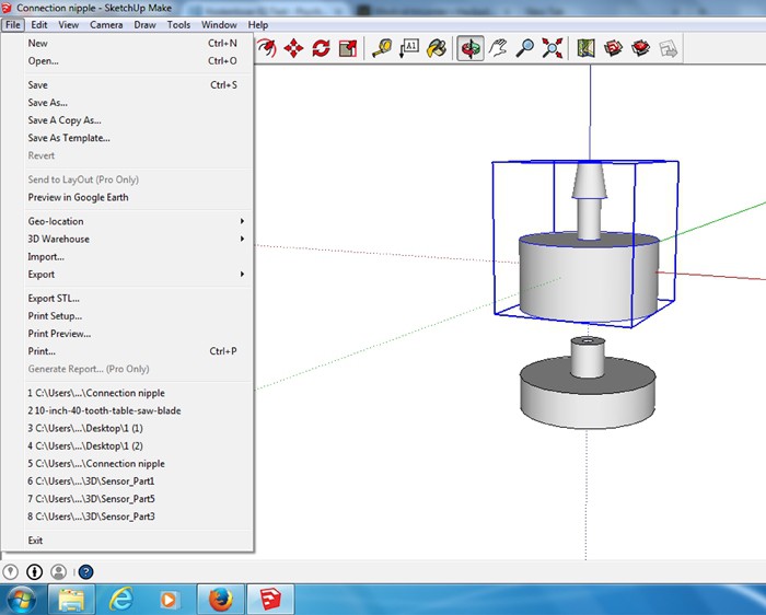
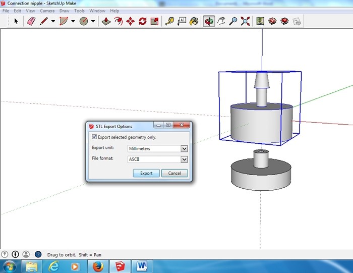
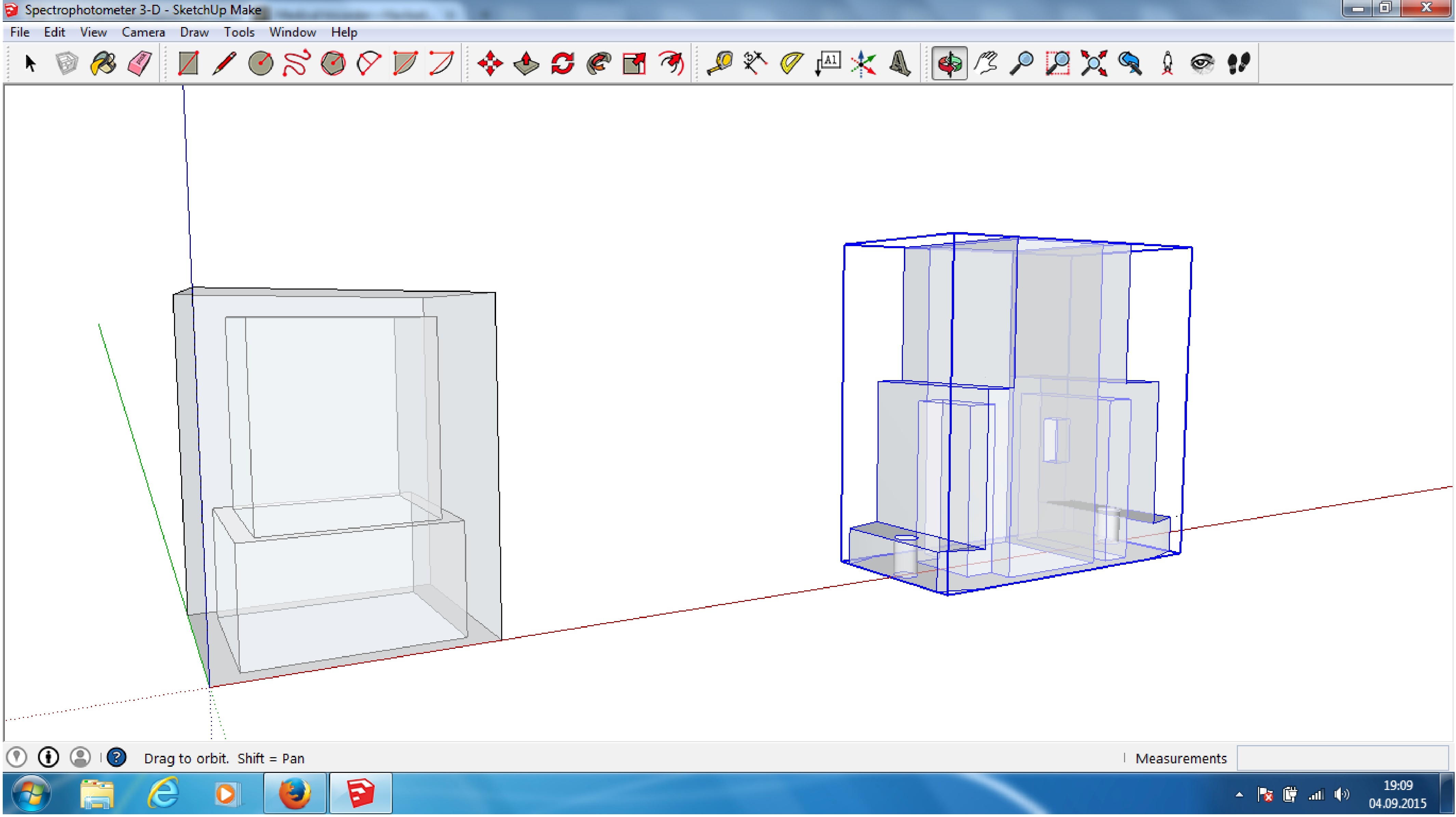
Open connection nipple 3-D drawing with Sketchup 2014. Select the first part. Then click on the drop down menu for 'File' and select 'Export STL...'. When the 'STL Export Options' window opens, select 'Export selected geometry only', 'Export unit: Millimeter' and 'File format: ASCII'. Save the STL file. Do the same with the second part.
![]()
3-D print both parts (PLA) using highest possible settings regarding strength and quality, e.g. 90% infill, layer height 0.1mm.![]()
Do the same with the spectrometer Sketchup model:
![]()
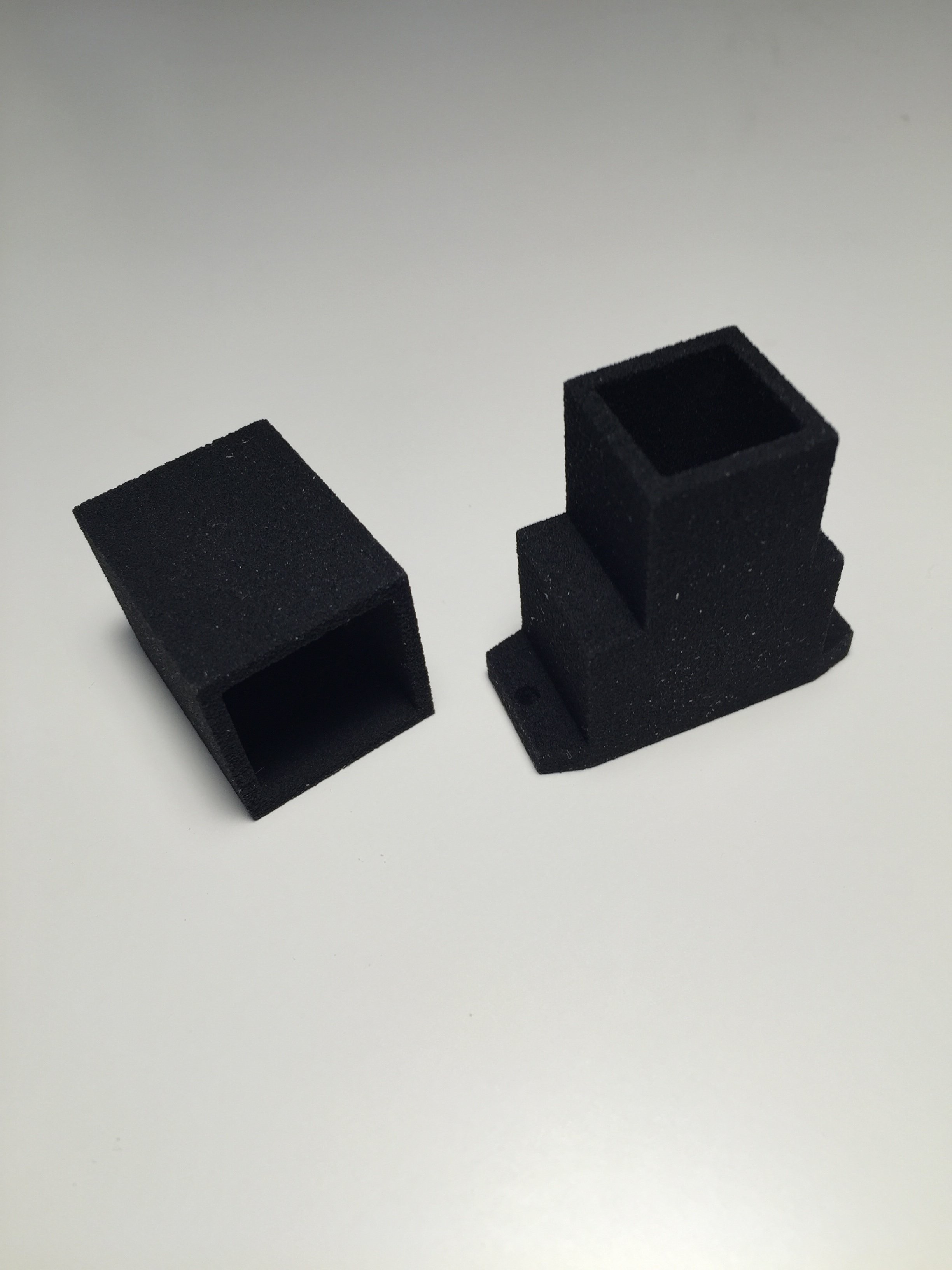
Use a fab house who can do PMMA (black)/binding agent printing. Result should look like this:
![]()
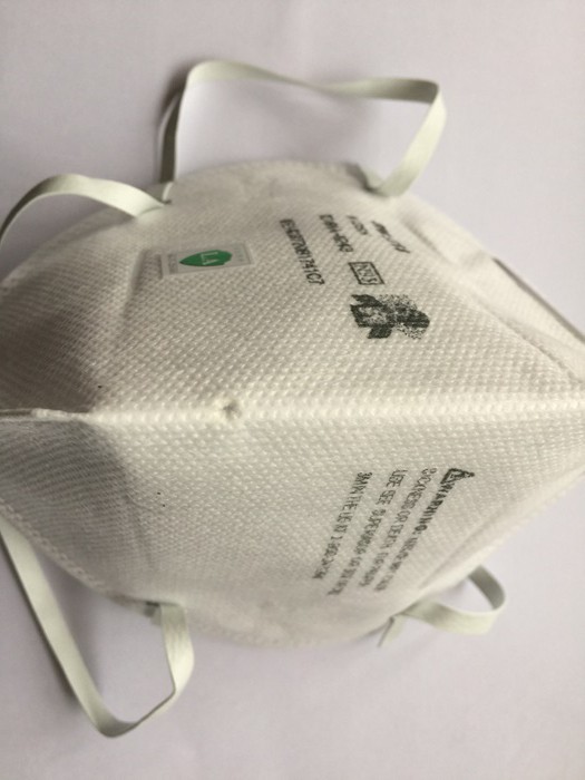
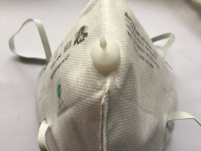
Use a sharp object (scissors or screwdriver) and drill a small hole (Ø 3mm) into the middle of the mouth area of the disposable respirator- half-mask.
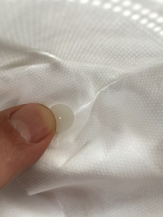
Push the connection nipple counterpart from inside of the mask thru the hole. Make sure the feed-through of the counterpart isn't blocked by textile fibers of the mask.![]()
Press fit the connection nipple on the outer side of the mask.![]()
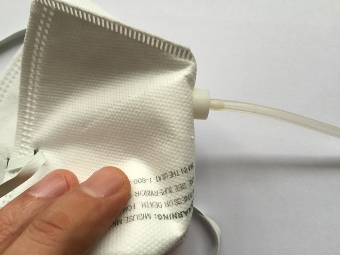
Attach one end of the silicone hose to the mask, The hose shouldn't have a length greater than 0.5m.![]()
Attach the other end of the silicone hose to the pressure sensor on the shield.![]()
![]()
Mask, connection nipple and silicon hose are disposable devices. Never reuse, wash or disinfect them!
-
4Step 4
Power down your Arduino before you connect the medical tricorder shield to it. The USB type B port is really a minus development of the Arduino Mega regarding shields, because the blank USB type B port can cause short circuits or other interferences by touching exposed vias or traces on the bottom side of the shield. I recommend to cover the USB port on the Arduino Mega by a piece of duct tape as seen below to avoid this problem:
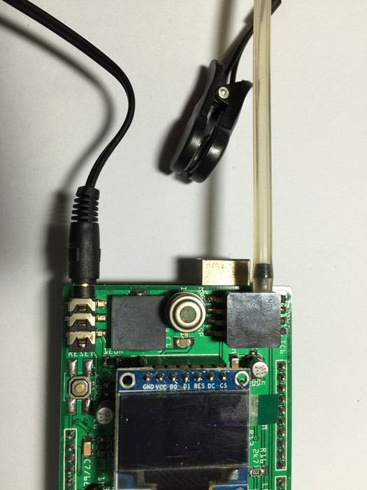
Next, connect the ear lobe pulse sensor as seen below.![]()
![]() Now, power the Arduino Mega by connecting it via USB cable with your computer or laptop. Do not power the Arduino via a power adapter. Hazard of electrical shock if the power adapter has a malfunction!
Now, power the Arduino Mega by connecting it via USB cable with your computer or laptop. Do not power the Arduino via a power adapter. Hazard of electrical shock if the power adapter has a malfunction!![]() The heart beat indicator LED should turn on. Clamp the ear lobe pulse sensor onto your left or right earlobe. The LED should start to flash with the frequency of your heart beat. If not adjust the gain via the trimmer by using a small screw driver, till it does.
The heart beat indicator LED should turn on. Clamp the ear lobe pulse sensor onto your left or right earlobe. The LED should start to flash with the frequency of your heart beat. If not adjust the gain via the trimmer by using a small screw driver, till it does.Open the source code in the Arduino IDE. Make sure you have all necessary libraries installed. Select the correct board (Arduino Mega 2560 or Mega ADK) and serial port in the IDE. Download the source code to the Arduino Mega. The medical tricorder is now ready to use.
Important note: The medical tricorder is an ongoing research project and is provided for educational purposes only. It should not be used for the diagnosis or treatment of any health problem or disease. It is not intended to replace clinical judgment or guide individual patient care in any manner.
Medical tricorder
Using artificial intelligence to identify a disease by its symptoms


 Now, power the Arduino Mega by connecting it via USB cable with your computer or laptop. Do not power the Arduino via a power adapter. Hazard of electrical shock if the power adapter has a malfunction!
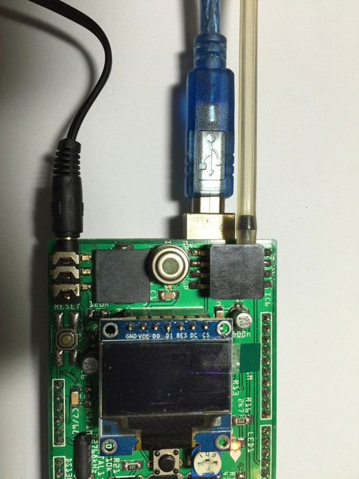 The heart beat indicator LED should turn on. Clamp the
Discussions
Become a Hackaday.io Member
Create an account to leave a comment. Already have an account? Log In.