Close
0%
0%

Medical tricorder

Using artificial intelligence to identify a disease by its symptoms

Similar projects worth following
One billion people lack access to health care systems. 36 million people die each year caused by noncommunicable diseases, such as cardiovascular disease, cancer, diabetes and chronic lung diseases. Over 7.5 million children under the age of 5 die from malnutrition and mostly preventable diseases, each year. Tuberculosis kills 1.7 million people each year. 1.6 million people still die from pneumococcal disease, more than half of the victims are children. Malaria causes over 780,000 deaths annually. 33.4 million living with HIV...

We need access to health care around the world, without having to rely on a doctor or nurse.

From Wikipedia, the free encyclopedia: A medical tricorder is a handheld portable scanning device to be used by consumers to self-diagnose medical conditions within seconds and take basic vital measurements. The word "tricorder" is an abbreviation of the device's full name, the "TRI-function reCORDER", referring to the device's primary functions; Sensing, Computing and Recording.

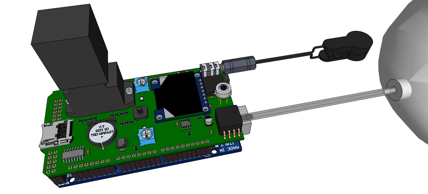
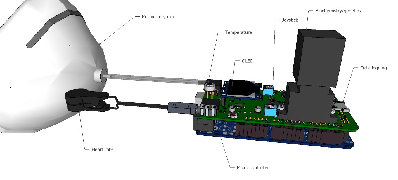
We will sense the 3 basic vital signs, which are body temperature, pulse rate and respiration rate. We will process (compute) these data using naive Bayes classifiers trained in a supervised learning setting for medical diagnosis beside other tools. And we will record the data (on a SD card).

The medical tricorder works in absence of internet, smart phones and computers, because where it probably will be used aren't such things available for the people in need.


1. Directly diagnosed diseases

Following diseases can be directly diagnosed, just comparing measured data to look-up-tables:

Body temperatureHeart rateRespiratory Rate
Direct diagnosesHypothermia
Fever (Hyperthermia, Hyperpyrexia)
Bradycardia
Tachycardia
Bradypnea
Tachypnea


a) Body core temperature classification

ClassBody core temperature
Hypothermia< 35 °C
Normal36.5-37.5 °C
Fever> 38.3 °C
Hyperthermia> 40.0 °C
Hyperpyrexia> 41.5 °C

b) Resting heart rate

AgeResting heart rate
0-1 month70-190 bpm
1-11 months80-160 bpm
1-2 years80-130 bpm
3-4 years80-120 bpm
5-6 years75-115 bpm
7-9 years70-110 bpm
> 10 years60-100 bpm (Well-trained athletes: 40-60 bpm)

c) Respiratory rate

Age
Respiratory Rate
0-2 months25-60 bpm
3-5 months25-55 bpm
6-11 months25-55 bpm
1 year20-40 bpm
2-3 years20-40 bpm
4-5 years20-40 bpm
6-7 years16-34 bpm
8-9 years16-34 bpm
10-11 years16-34 bpm
12-13 years14-26 bpm
14-16 years14-26 bpm
≥ 17 years14-26 bpm


2. Naive Bayes classifier at a glance

Naive Bayes classifiers are commonly used in automatic medical diagnosis. There are many tutorials about the naive Bayes classifier out there, so I keep it short here.

Bayes' theorem:

\color{White} \large P \big(h|d)= \frac{P\big(d|h)\times P\big(h)}{P\big(d)}

h: Hypothesis
d: Data
P(h): Probability of hypothesis h before seeing any data d
P(d|h): Probability of the data if the hypothesis h is true

The data evidence is given by

\color{White} \large P \big(d)= \sum_h P \big(d|h)  \times P \big(h)where P(h|d) is the probability of hypothesis h after having seen the data d.

Generally we want the most probable hypothesis given training data. This is the maximum a posteriori hypothesis:

\color{White} \large h_{MAP}=arg~max_{h\in H} P \big(h|d)=arg~max_{h\in H} \frac{P \big(d|h)\times P\big(h)}{P\big(d)}

H: Hypothesis set or space

As the denominators P(d) are identical for all hypotheses, hMAP can be simplified:

\color{White} \large h_{MAP}=arg~max_{h\in H} P \big(d|h) \times P \big(h)If our data d has several attributes, the naïve Bayes assumption can be used. Attributes a that describe data instances are conditionally independent given the classification hypothesis:

\color{White} \large P \big(d|h)=P \big(a_{1},...,a_{T}|h) = \prod_t P \big(a_{t}|h) \color{White} \large h_{NB}=arg~max_{h\in H} P(h)\times \prod_t P \big(a_{t}|h)    3. Common cold/flu classifier

Every human depending on the age catches a cold 3-15 times a year. Taking the average 9 times a year and assuming a world population of 7· 10^9, we have 63· 10^9 common cold cases a year. Around 5·10^6 people will get the flu per year. Now we can compute:

\color{White} \large P \big(Flu)= \frac{5 \times 10^{6}}{5 \times 10^{6}+63 \times 10^{9}}  \approx 0.00008\color{White} \large P \big(Common~cold)= \frac{63 \times 10^{9}}{5 \times 10^{6}+63 \times 10^{9}}  \approx0.99992This means only one of approx. 12500 patients with common cold/flu like symptoms has actually flu! Rests of the data are taken from here. The probability-look-up table for supervised learning looks then as follows:

ProbFluCommon cold
P(h)0.000080.99992
P(Fatigue|h)0.80.225
P(Fever|h)0.90.005
P(Chills|h)0.90.1
P(Sore throat|h)0.550.5
P(Cough|h)0.90.4
P(Headache|h)0.850.25
P(Muscle pain|h)0.6750.1
P(Sneezing|h)0.250.9

Therefore:

\color{White} \large h_{NB}=arg~ max_{h\in  \big\{Common~cold,Flu\big\}} P(h)\times P(Fatigue|h) \times P(Fever|h) \times P(Chills|h) \times P(Sore~throat|h) \times P(Cough|h) \times P(Headache|h) \times P(Muscle~pain|h) \times P(Sneezing|h)

Note: The probability that an event A is not occurring is given by

\color{White} \large P  \big(\neg A\big) =1-P \big(A\big)Multiplying a lot of probabilities, which are between 0 and 1 by definition, can result in floating-point underflow. Since

\color{White} \large \log⁡(x\times y)=\log⁡(x)+\log⁡(y) it is better to perform all computations by summing logs of probabilities rather than multiplying probabilities. The class with highest final un-normalized log probability score is still the most probable:

\color{White} \large h_{NB}=arg~ max_{h\in H} \log \big(P(h)\big)+ \sum_t \log \big(P\big(a_{t}|h\big)\big) An according Arduino sketch using the serial monitor and computer keyboard as interface for testing would look as following:

void setup() {
  Serial.begin(9600);
}

void loop() {
  flu_cold_classifier();
}

void diagnosis(boolean fatigue, boolean fever,...
Read more »

View all 49 components

  • Breathing gas analysis and respiration rate

    M. Bindhammer09/26/2015 at 20:13 0 comments

    Just two examples: If your breath has an acetone-like odor, it's a warning sign for diabetes and if your breath has an ammonia-like odor, it's a warning sign for chronic kidney failure.

    Target gases of the FIGARO TGS 2620 sensor are amongst other substances: ammonia, propionic acid, acetic acid, acetone, benzene and ethanol, which makes this gas sensor with a heater current of only 42 mA and a standard TO-5 package suitable for simple breathing gas analysis.

    Fig. 1

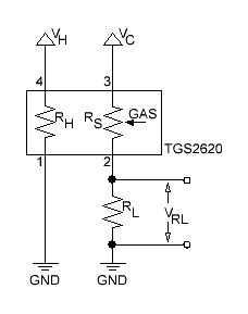
    The basic measuring circuit for the TGS 2620 is shown below:

    Fig. 2

    The formula to determine RS is given by:

    The value of RL should be determined to make the output voltage half of VC at the most critical value in the sensor application, because then the output voltage of the voltage divider is most sensitive to the gas concentration.

    The relationship between sensor resistance and the concentration of deoxidizing gas can be expressed by the following equation over a certain range of gas concentration:

    where

    RS = Sensor element resistance

    A = Constant for this particular gar sensor

    C = Gas concentration

    α = Slope of the RS curve on a log/log plot.

    The equation for the minimum value of the load resistance RL to limit power to the sensor element resistance RS is given by:

    VC = 5 V and PMAX = 15 mW = 0.015 V·A, thus

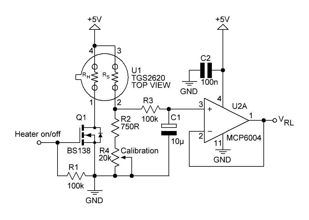
    A little bit more advanced gas sensing circuit is shown in next figure:

    Fig. 3


    Q1 turns the heating element of the gas sensor on or off. R2 and R4 acting as a variable load resistor. The R3/C1 circuit provides a low-pas filter with a cut-off frequency of

    The op-amp U2A is connected to an unity buffer amplifier circuit.

    Breathing gas analysis and respiration rate system overview:

    Fig. 4

    If the patient breathes out, breathing gas enters the system and must overcome the small resistance of the check valve. The resulting pressure increase will be recognized by the pressure sensor. The breathing gas flows then to the gas sensor, where it will be analyzed. When the patient breathes in, the check valve closes and no false air intake can take place.

    Pressure sensor will be a MPXV5004GC6U from Freescale with a pressure range of 0-3.92 kPa (0-400 mm H₂O).

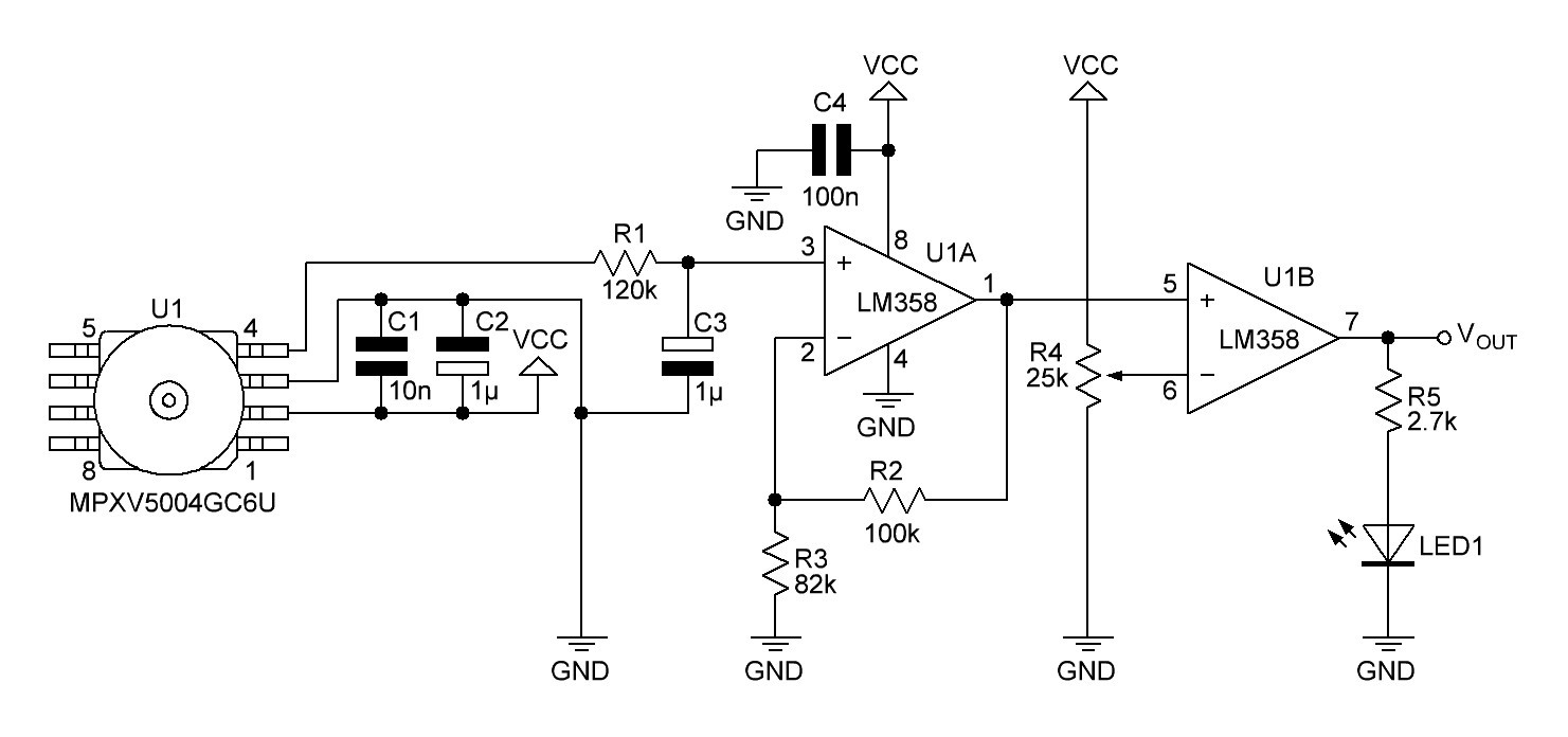
    The gauge pressure is quite small when breathing out, so the output voltage of the pressure sensor must be amplified. This is done by a non-inverting amplifier:

    Fig. 5

    C5 and C6 are recommended decoupling capacitors. R9/C7 are connected to a low-pass RC filter with a cut-off frequency of

    The output voltage of the non-inverting amplifier (and input voltage VIN of the non inverted Schmitt trigger) is given by


    Assuming a single power supply of the op-amp and a rail-to-rail output, high threshold voltage VH, low threshold voltage VL and hysteresis H are computed as follows:

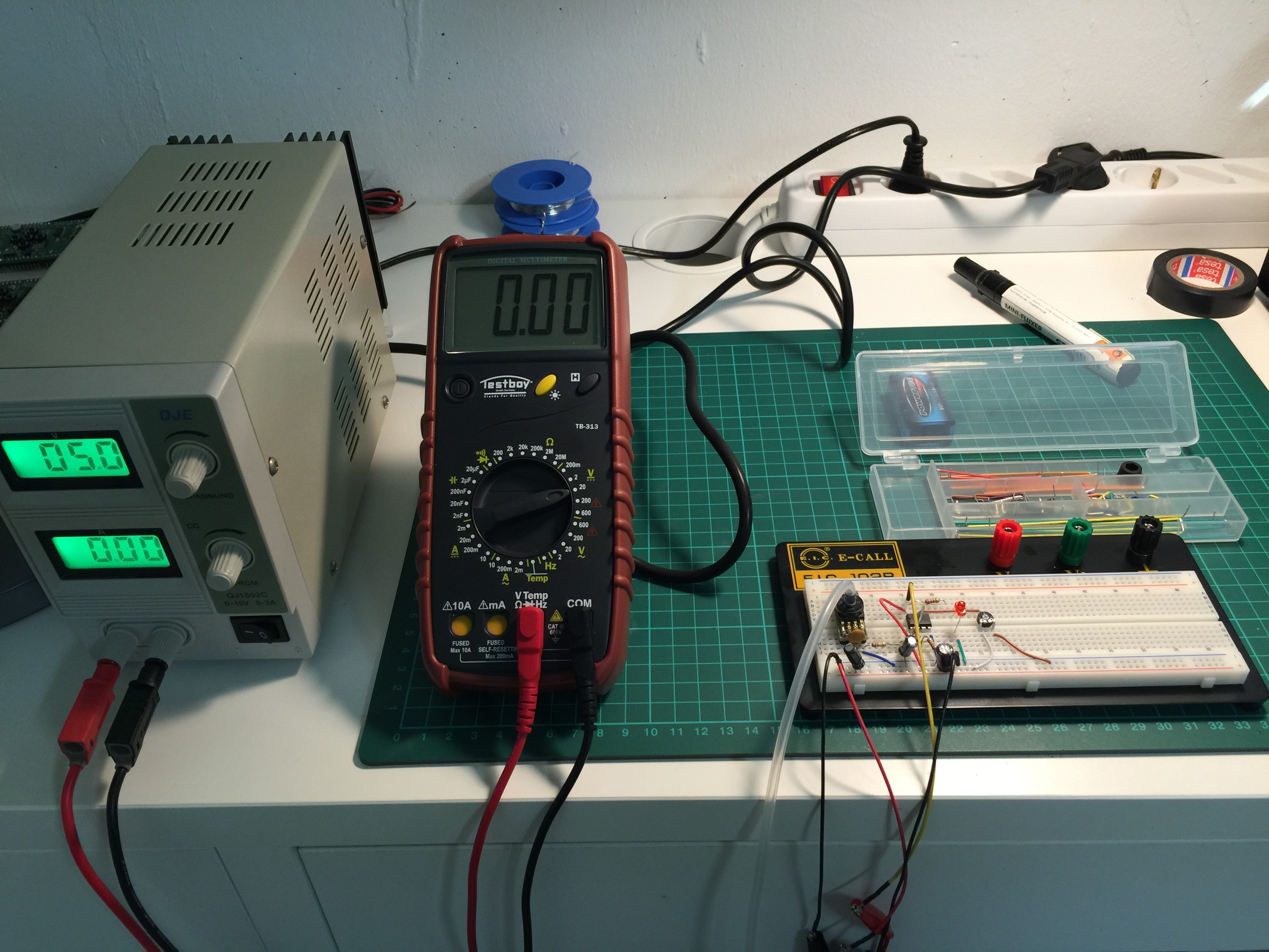
    After experimenting with several setups I decided to use a non inverting comparator and a low pass filter with a cut-off frequency of 1.6 Hz instead of the Schmitt trigger.

    References:

    FIGARO TGS 2620 datasheet

    Technical Information on Usage of TGS Sensors for Toxic and Explosive Gas Leak Detectors

    MPXV5004GC6U datasheet

    Noise Considerations for Integrated Pressure Sensors

    Non-Inverting Schmitt Trigger Calculator

    LM358 datasheet

  • Pulse oximeter

    M. Bindhammer09/15/2015 at 17:17 1 comment

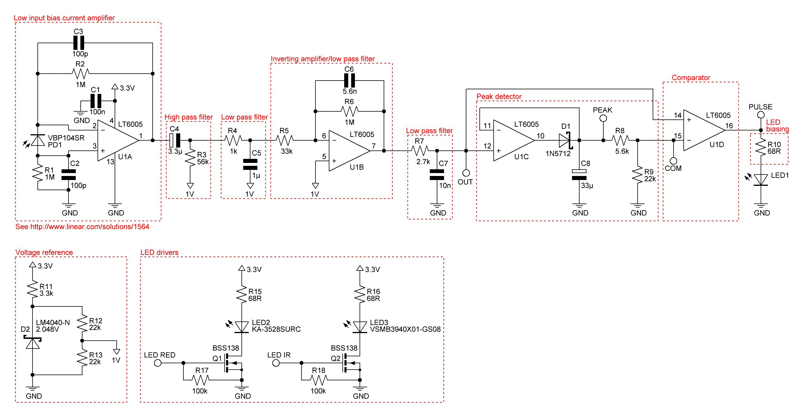
    The current heart beat monitor works quite well, but a pulse oximeter would be better to get the pulse rate and the saturation of peripheral oxygen SpO2.

    After a lot of research I found this promising reflective pulse oximeter design. The circuit outputs amongst other things directly the peak IR and red light voltages. The simple equation

    is used, and S represents the value of StO2 in a calibration table.

    I will use a commercially available pulse oximeter to approximate a function of the saturation of peripheral oxygen depending on S.

    Redrawn and slightly modified schematic:

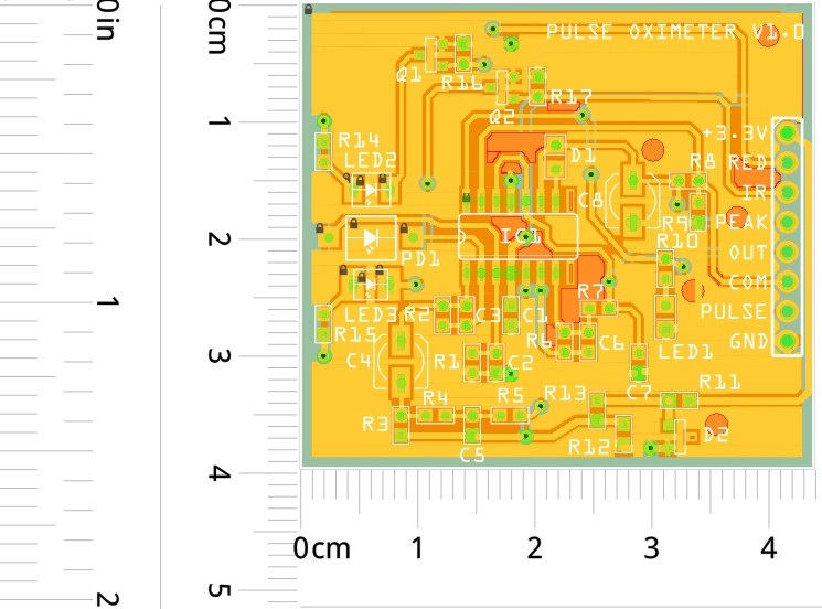
    Next step will be to build a prototype and see how it works.

    PCB layout of the prototype:

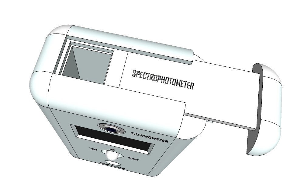
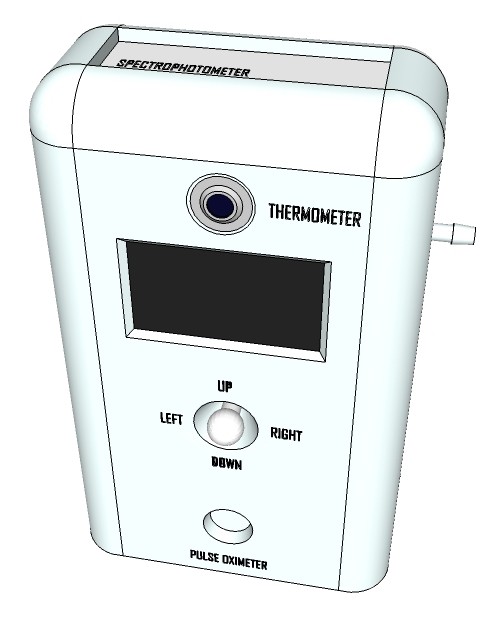
  • Artist’s rendition of the 'productized' design

    M. Bindhammer09/13/2015 at 13:00 0 comments

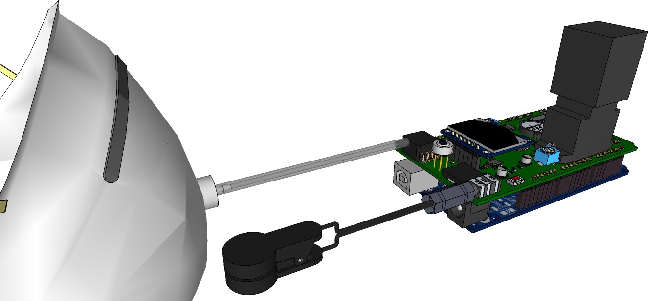
    Rendering research apparatus (current stage):

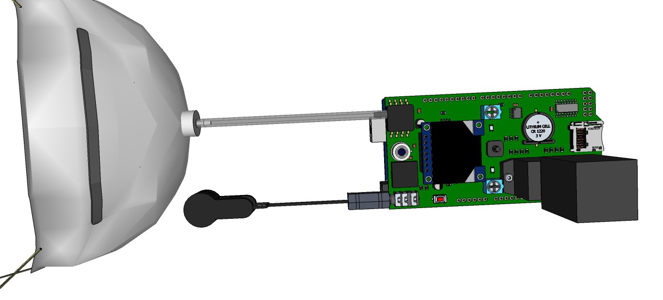
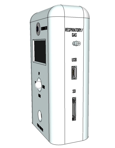
    Rendering finalized product:

  • More analytical reactions for spectrophotometry

    M. Bindhammer09/01/2015 at 17:54 0 comments

    I am quite busy to develop other analytical reactions for spectrophotometry these days. It is not always easy to get all the required chemicals as we have many restrictions in Germany regarding chemicals.

    First, I want to develop a pH test using a double indicator system comprising methyl red and bromothymol blue to cover the complete pH range. I need to do a couple of experiments to determinate the optimal mixture of both solutions. Methyl red is also used to detect E. coli bacterium.

    Second, I want to develop a nitrite test. Some of the gram negative bacteria species that most commonly cause urinary tract infections have enzymes that reduce the nitrate present in urine to nitrite. I will probably use Griess Reagent for nitrite determination. 1-Naphthylamine will be replaced by N-(1-naphthyl)ethylenediamine dihydrochloride because 1-Naphthylamine is carcinogenic. The required phosphoric acid is on the other hand not a problem to get as it is used in Germany as a rust remover.

    To get pure Potassium nitrite or Sodium nitrite as a private person is a problem in Germany because both are toxic. I think I need to extract it from curing salt.

    Preparing Griess Reagent

    To get 50 ml 5% phosphoric acid from commercially available 85% phosphoric acid, we compute:

    Means we need 5 parts 85% phosphoric acid and 80 parts deionized water.

    To obtain 50 ml of 5% phosphoric acid we therefor need:


    More information will follow as soon as I make progress.

  • My friend Lutz

    M. Bindhammer08/17/2015 at 17:08 1 comment

    I had a friend named Lutz. For some times we discussed the concept of a medical tricorder. He was sure, that medical tricorders will save lives in the future like defibrillators do now.

    Lutz passed away exactly 3 months ago in San Fransisco, probably on a heart attack at night in his hotel room. I was too late. Too late...

    RIP my friend, I'll never forget you.

  • Medical tricorder Rev. 3

    M. Bindhammer07/22/2015 at 18:16 0 comments

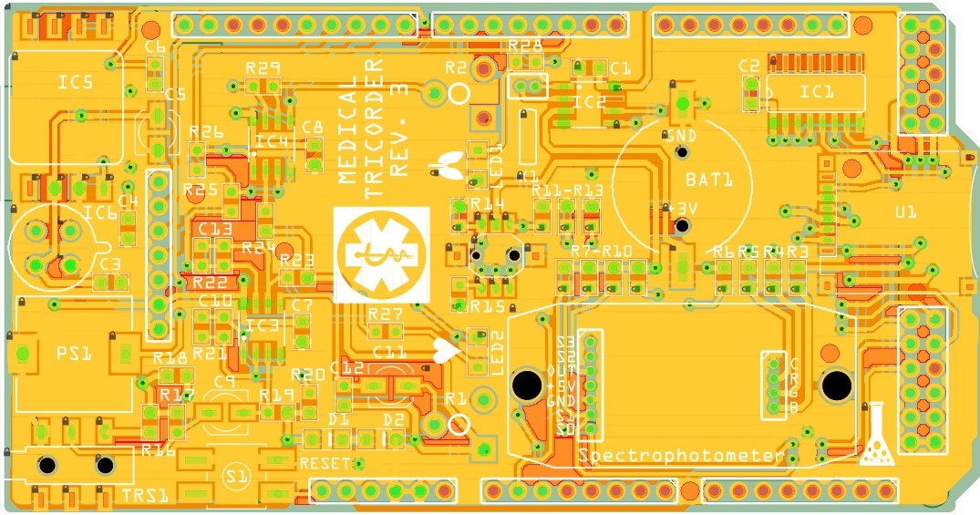
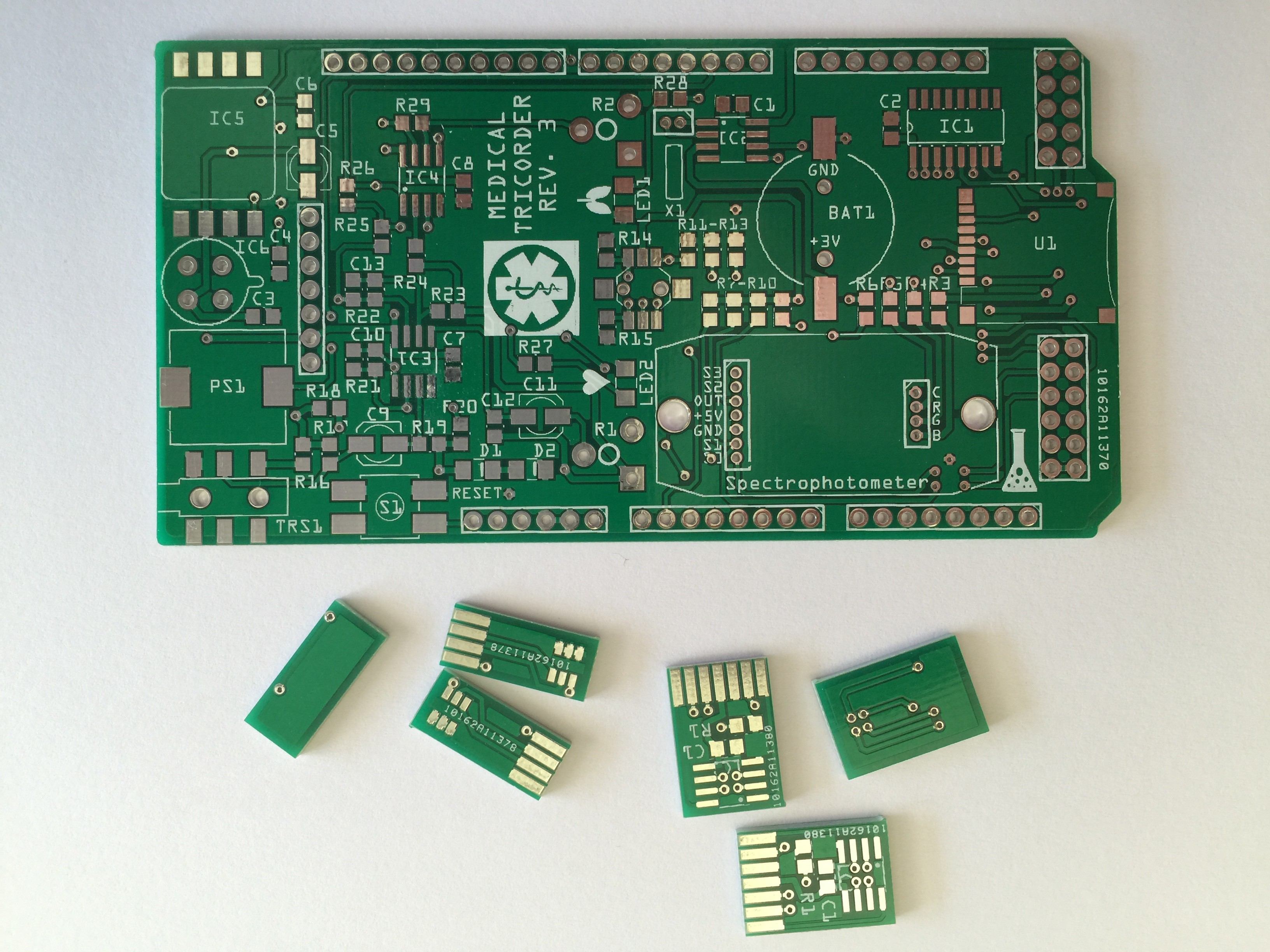
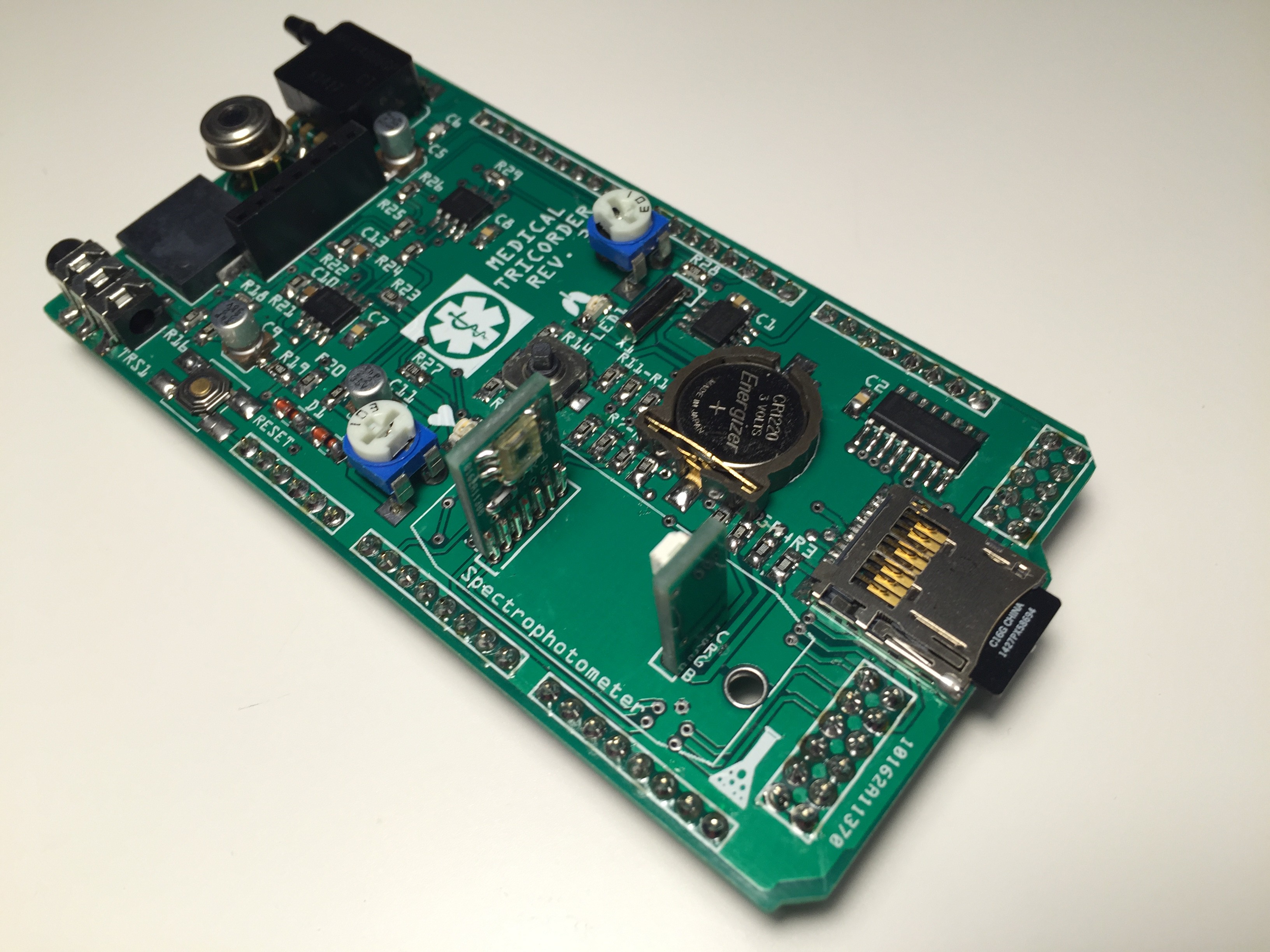
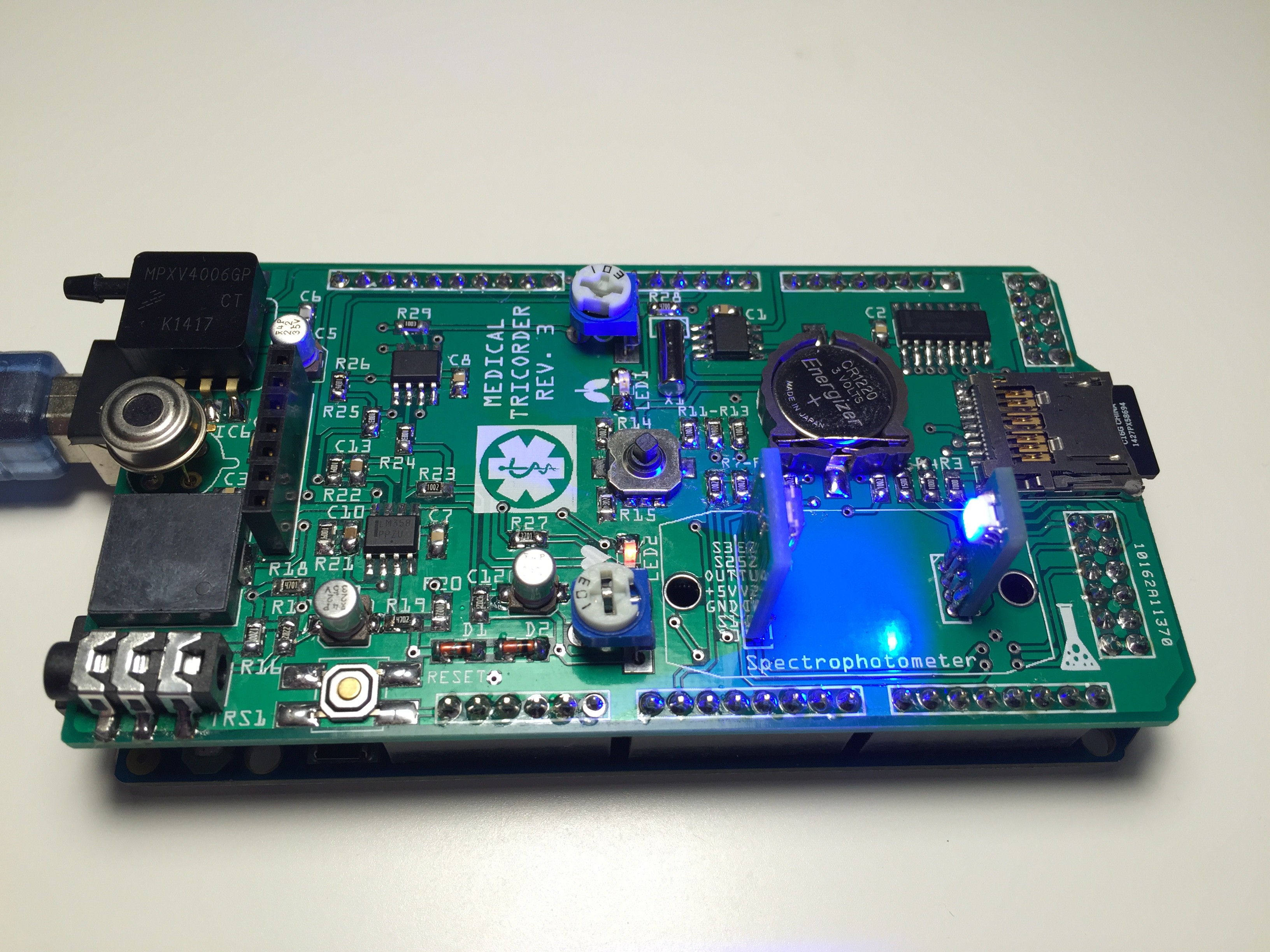
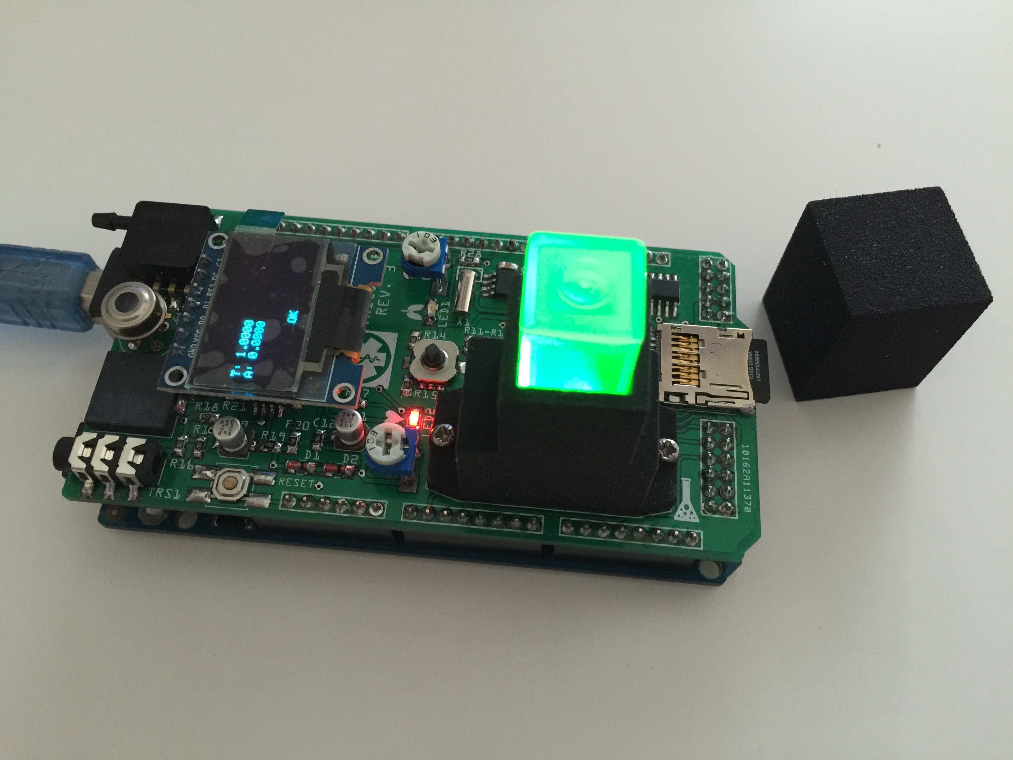
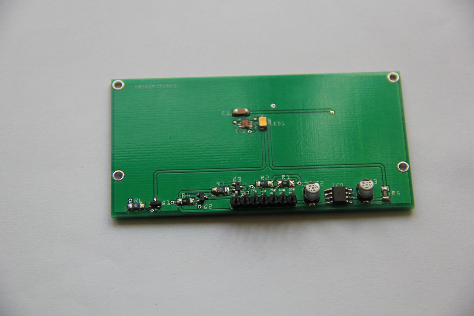
    I have started working on the third revision of the medical tricorder. So far I have routed the new shield and the two PCB's which will carry the color sensor and RGB LED for the spectrophotometer.

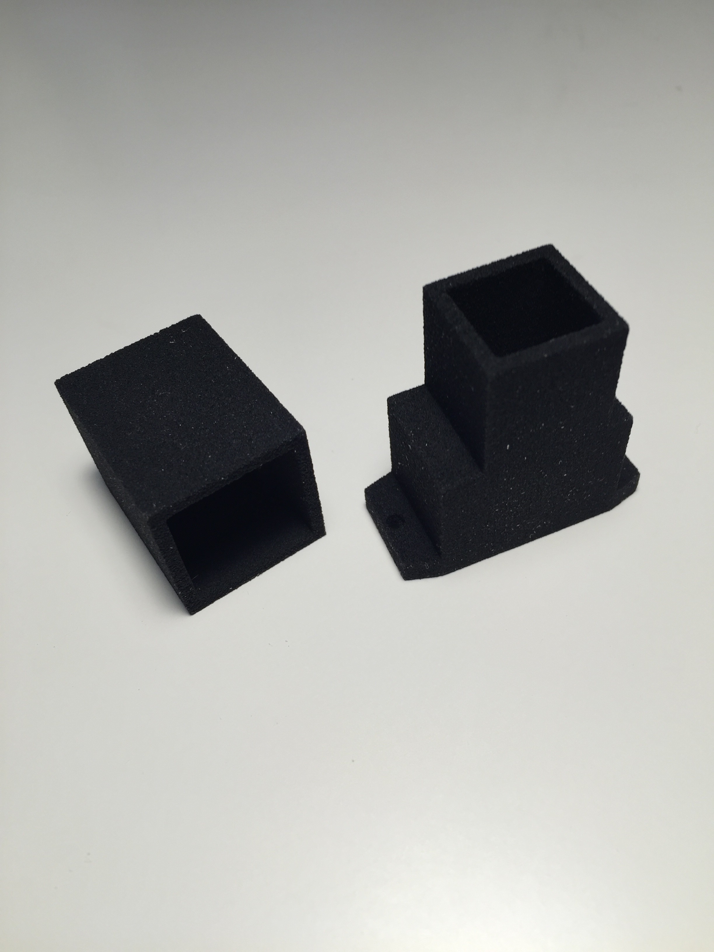
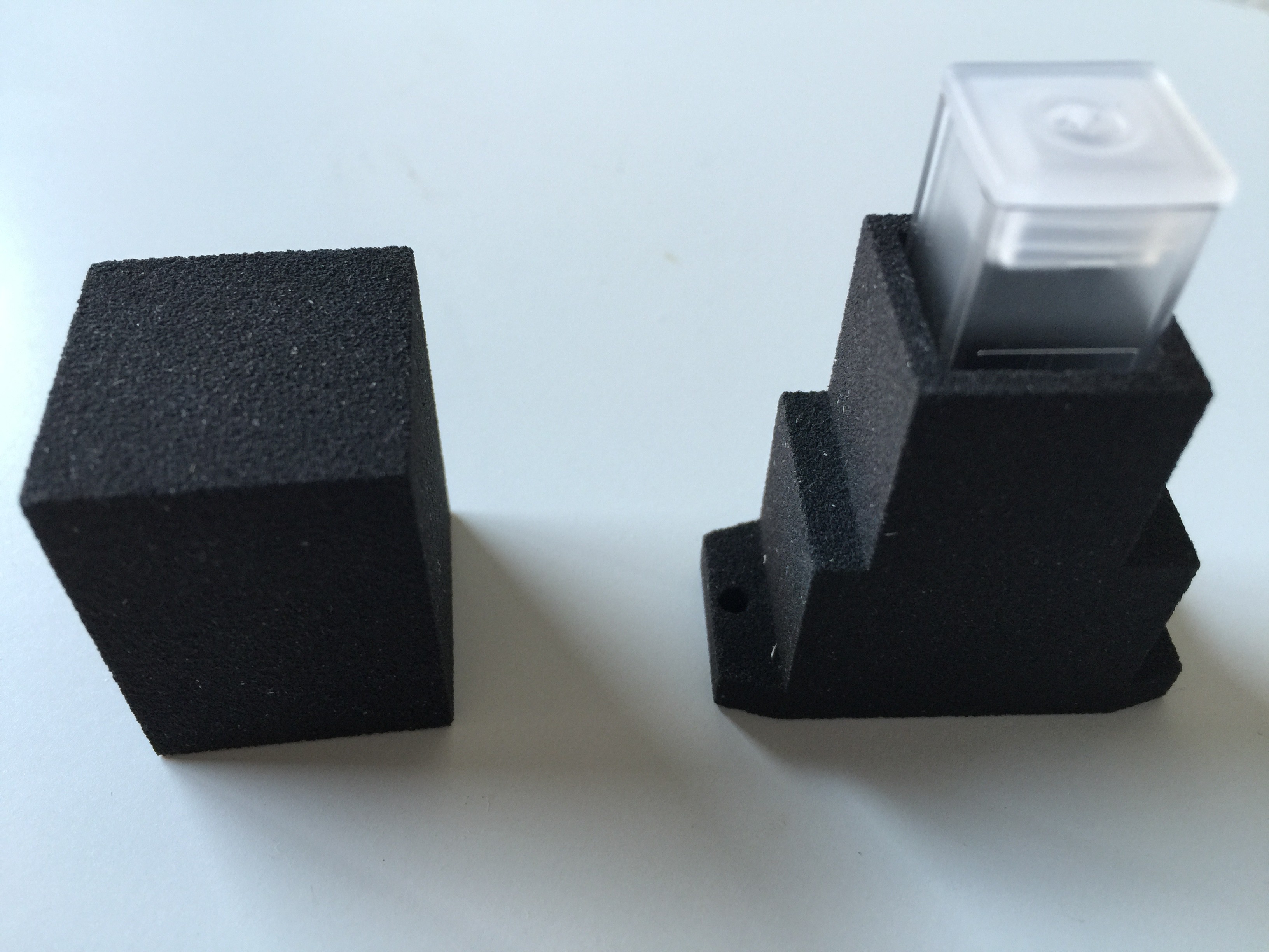
    The housing for the spectrophotometer was produced by applying a particle material (PMMA Polymethylmethacrylate) in layers, which is bonded together with a binding agent.

    Finally the cuvettes arrived:

    PCB's:

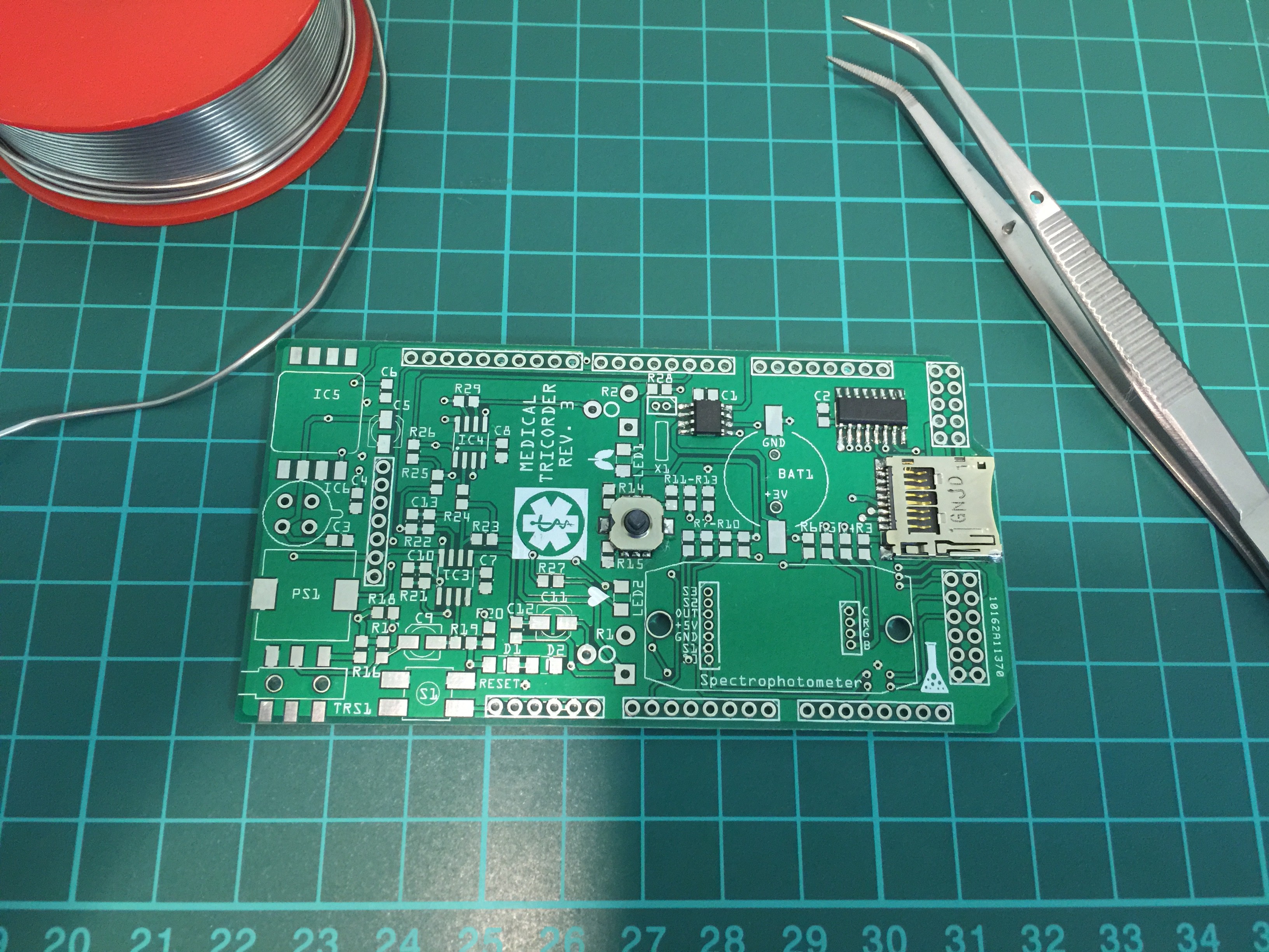
    Partly populated:

    PCB ready for some first tests:
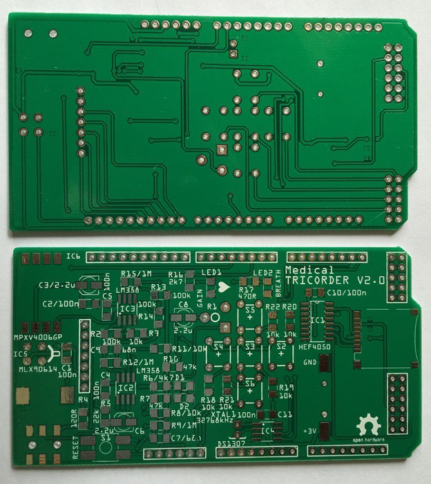
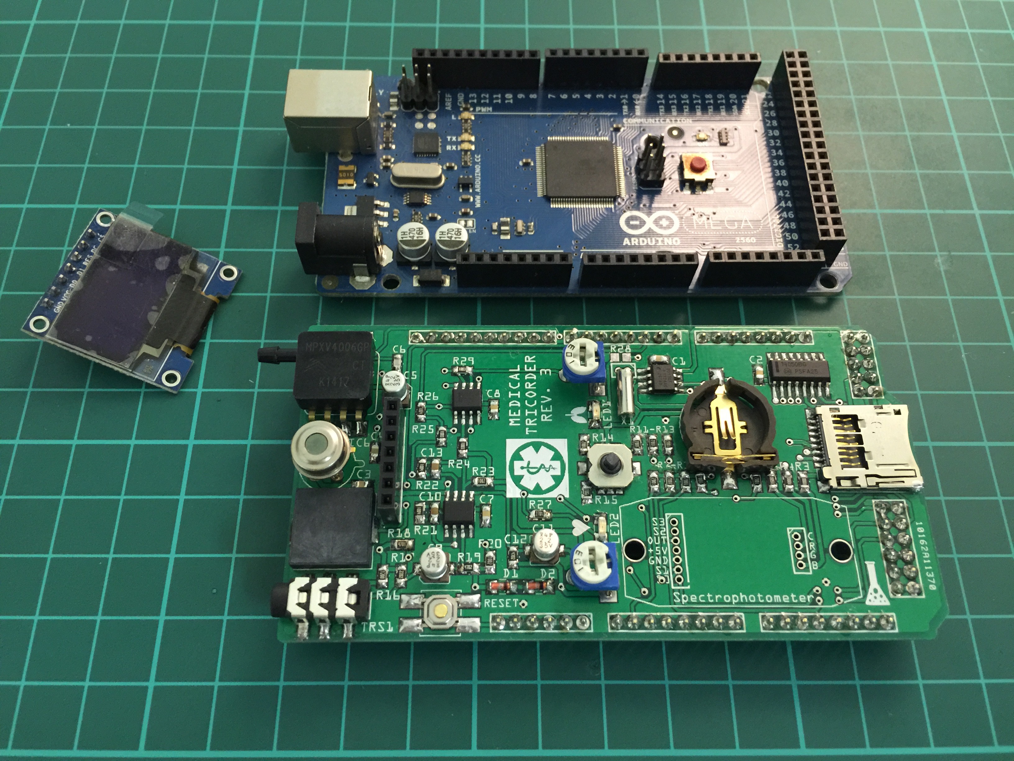
    Completely populated shield:

    Testing the RGB LED of the spectrophotometer:

    The next couple of days I will write code for the spectrophotometer. Once done, a short demonstration video will follow.

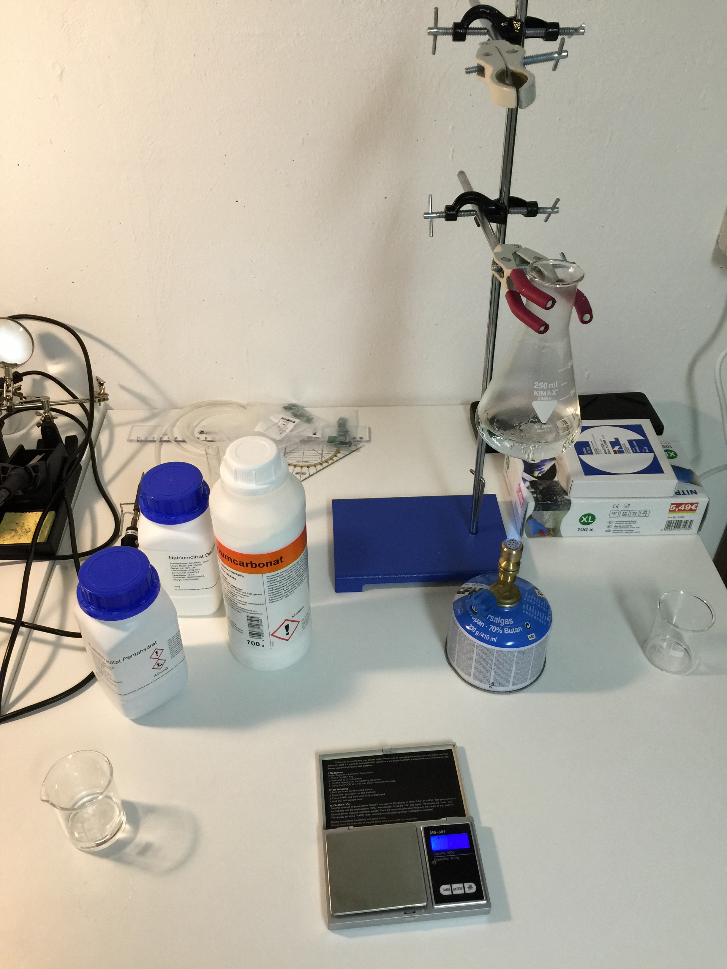
    In a first test I will use Benedict's solution to determinate glucose level in urine. Benedict's solution is prepared as following:

    (1) Benedict A: Dissolve 1.7 g of Copper (II) sulfate pentahydrate in 20 ml of deionized H2O.

    (2) Benedict B: Dissolve 17.3 g of Sodium citrate and 10 g of anhydrous Sodium carbonate in 70 ml warm deionized water.

    (3) Benedict's Reagent: Pour Benedict's solution A slowly into solution B and make up the volume to 100 ml . Mix well.

    Use this procedure to determinate glucose level by spectrophotometer.

    Preparing Benedict's reagent:

    General Benedict's reagent test (Glucose):

    Next step is to work out a concentration standard curve and derive a function by curve fitting.

    To do this, the main housing of the spectrophotometer needed some small modifications to fit well. I have updated the 3-D drawing and STL file. New sample will arrive in a couple of days from the fab house. Once arrived, I'll be able to finish spectrophotometer code and prepare standard glucose/Benedict's reagent samples to obtain a look-up table. In the mean time I will work on other code snippets like core temperature reading and heart beat.

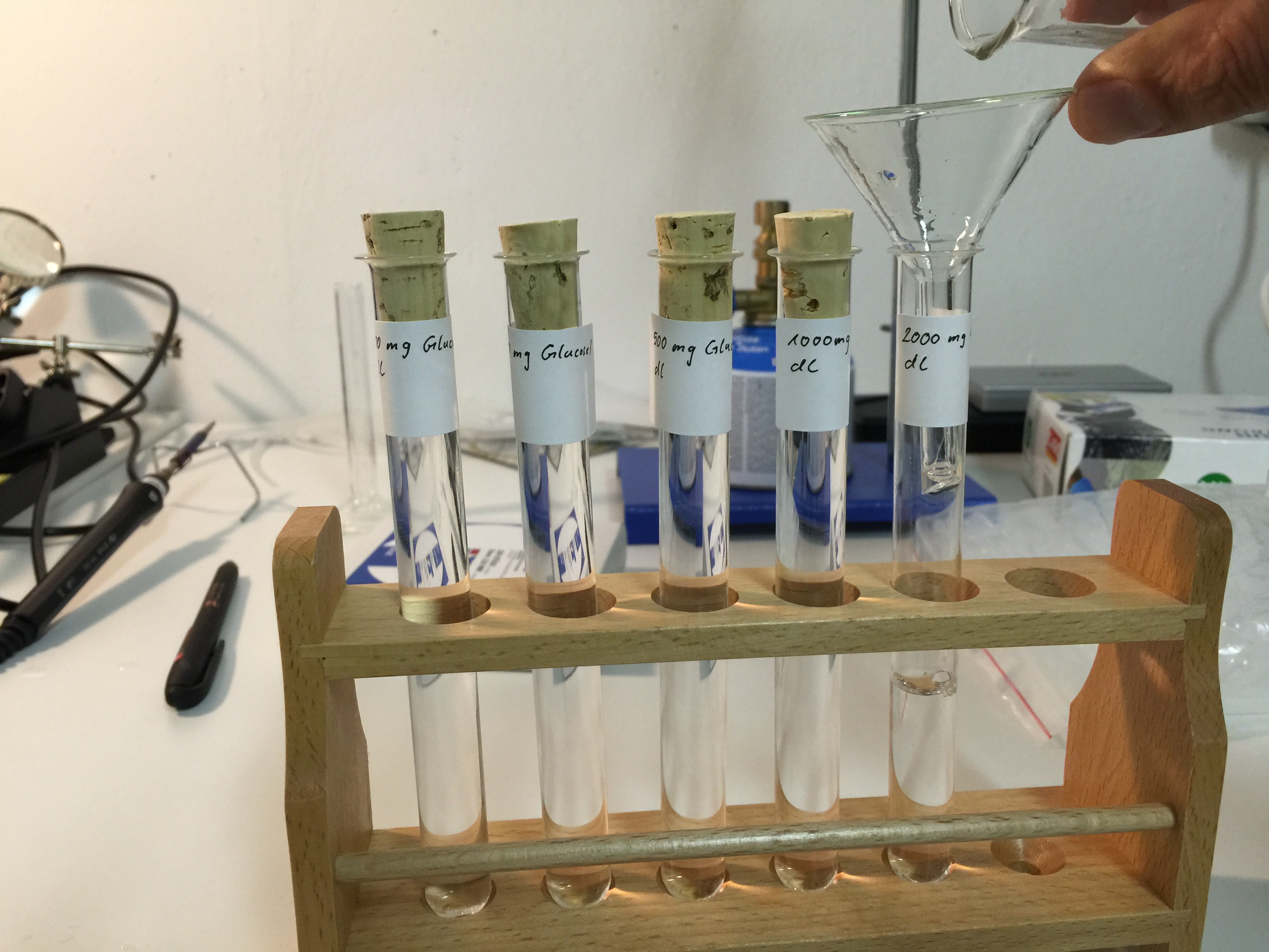
    The new housing of the spectrophotometer will arrive tomorrow, so I started to prepare different solutions (100 mg/dl, 250 mg/dl, 500 mg/dl, 1000 mg/dl, 2000 mg/dl) of D-(+)-Glucose monohydrate ≥ 99.0% for microbiology and deinoized water:First tests with the finished spectrophotometer:

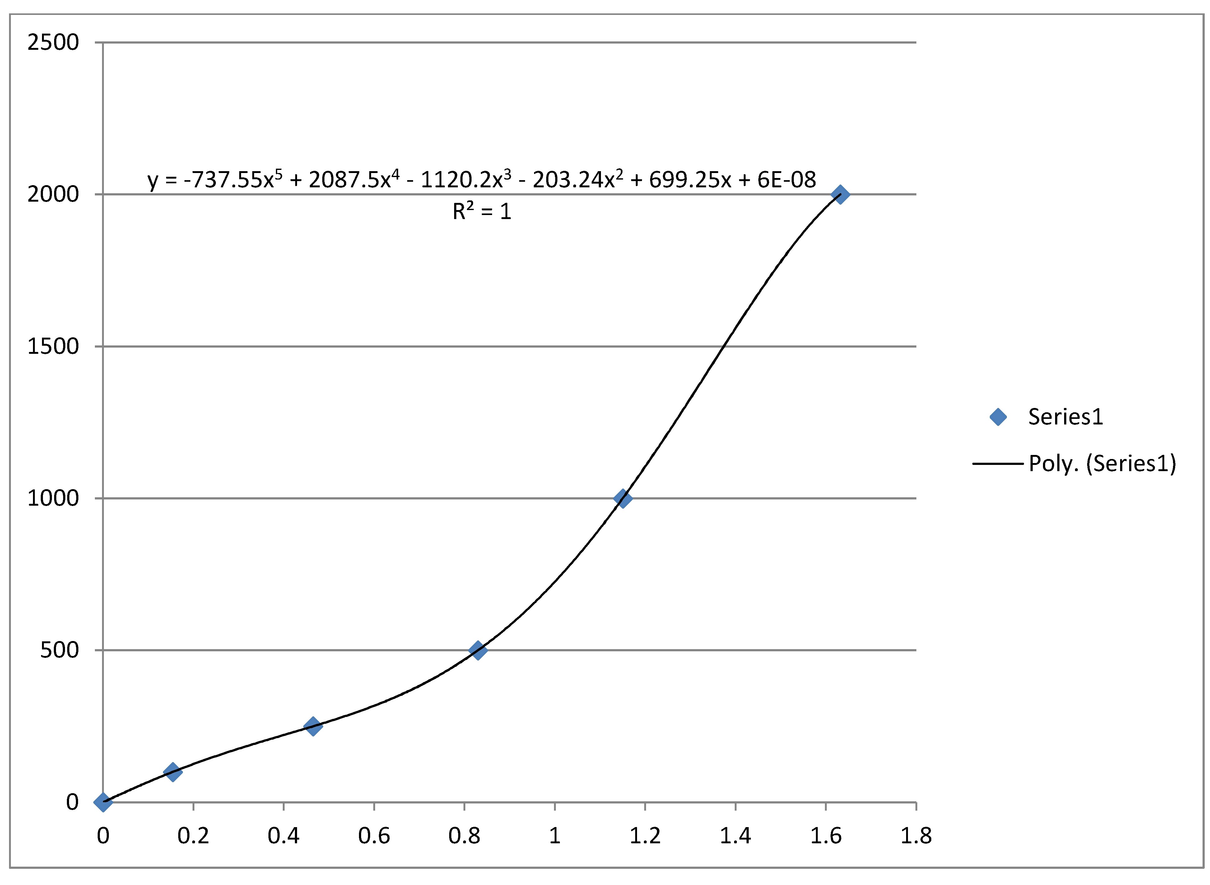
    For λ = 528 nm, read with no filter, 3 ml Glucose solution and 1 ml Benedict's reagent, heating mixture for 1 minute in a boiling water bath in each case I obtained following trendline made by Excel. x-axis: absorbance, y-axis: concentration mg Glucose/dl.

    The mass concentration is defined as the mass of a constituent divided by the volume of the mixture:

    Therefore the mass concentration under above mentioned circumstances is given by (neglecting the last term of the Quintic function):

    where A is the absorbance at a wavelength λ = 528 nm.

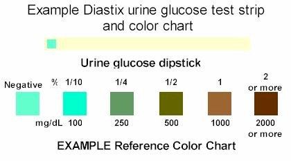
    We might overfitting the model but we can run an additional K-nearest neighbor classification to find the usual concentrations mentioned on a Urine test strip:

    Source: http://www.caninediabetes.org/pdorg/urine.html

    Presence of > 40 mg Glucose/dl Urine could already be an indication of diabetes or a kidney disease.

    Spectrophotometer demonstration video:

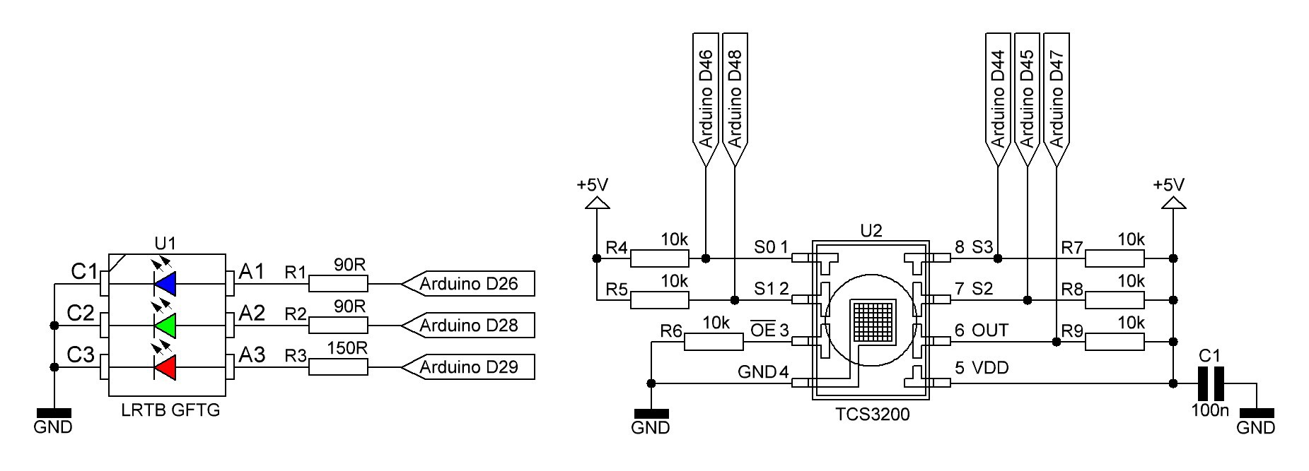
    Spectrophotometer schematic (temporary):

    R1 - R3 are series resistors for the RGB LED LRTB GFTG and R4 - R9 pull up/pull down resistors for the color sensor TCS3200. C1 is the usual decoupling capacitor for U2.

  • New lab in Germany

    M. Bindhammer07/21/2015 at 16:48 0 comments

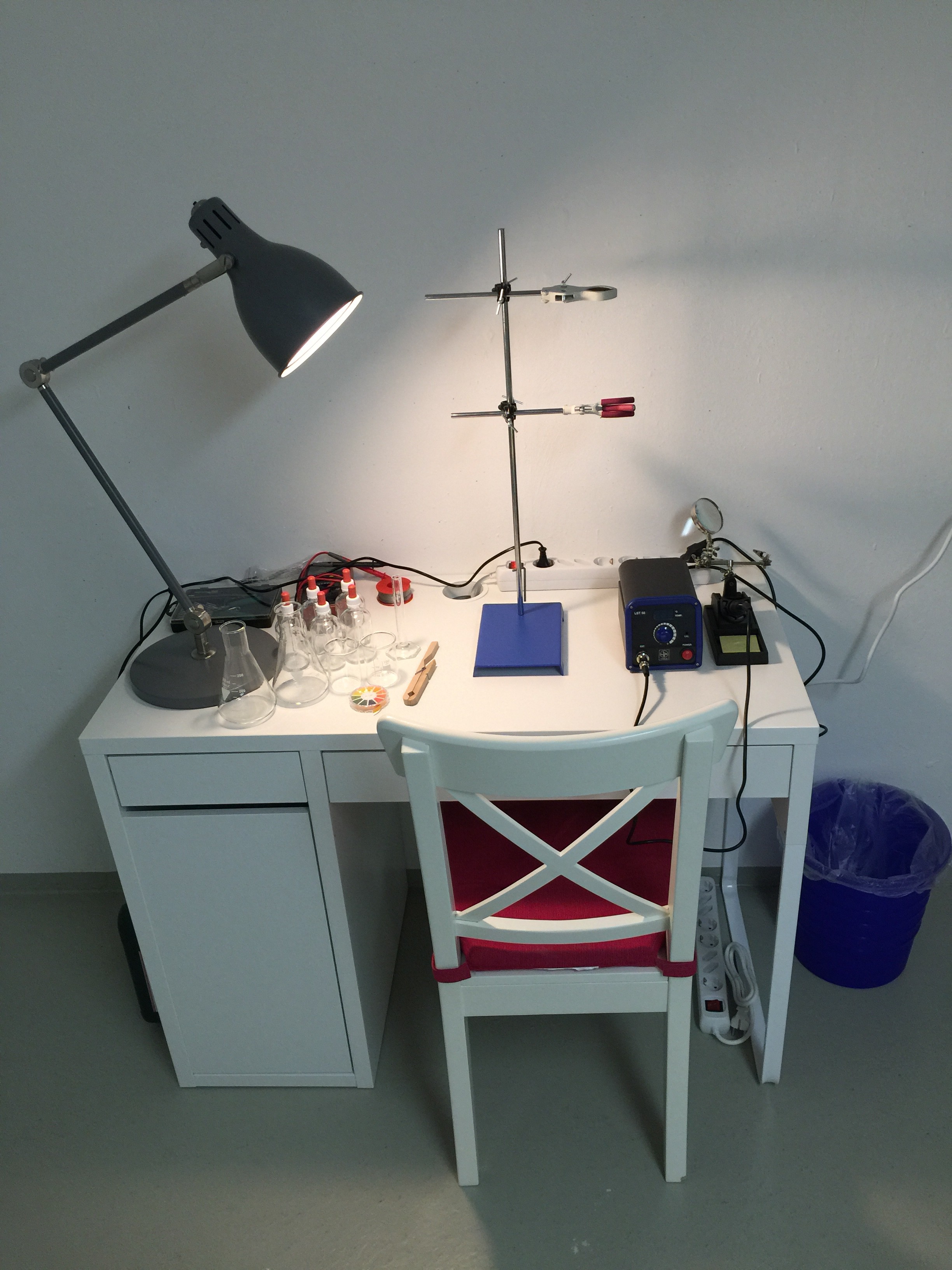
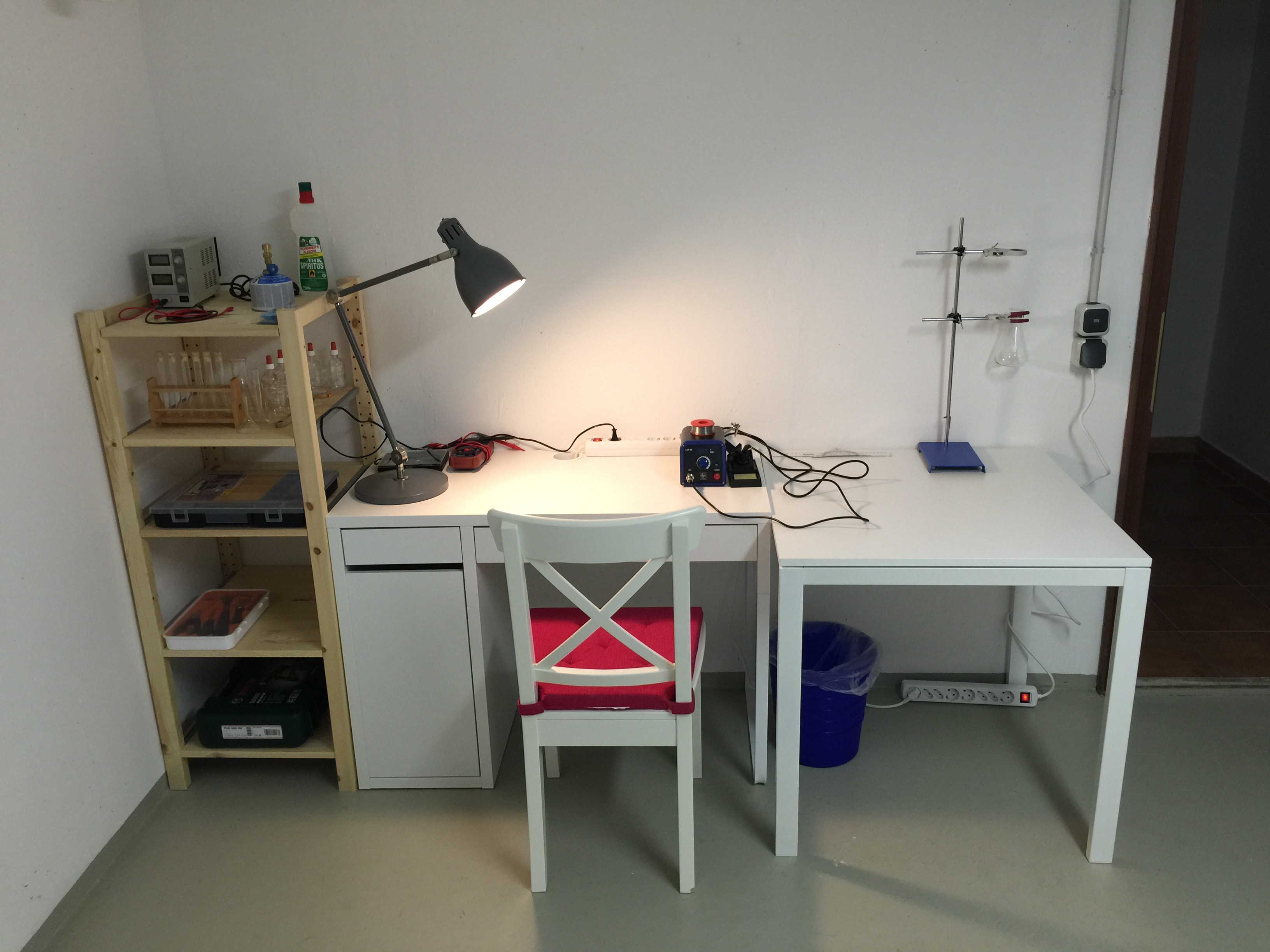
    I have been busy moving to Germany after nearly 9 years residence in China. I have rent a house and just started to build up a new chemistry and electronic lab in the basement to continue with my medical tricorder project. Picture below shows the lab (WIP):

  • New shield

    M. Bindhammer05/28/2015 at 06:47 0 comments

    I decided to design a new shield including the spectrophotometer beside some small modifications like gain control for the respiration sensor and a gas sensor to analyze the exhalation gases . After the shield and spectrophotometer is finished, I will focus on software and wetware for the tricorder. Things will slow down a bit as I will soon move to Germany with my family and I have to leave all my equipment and my chemistry lab here in China.

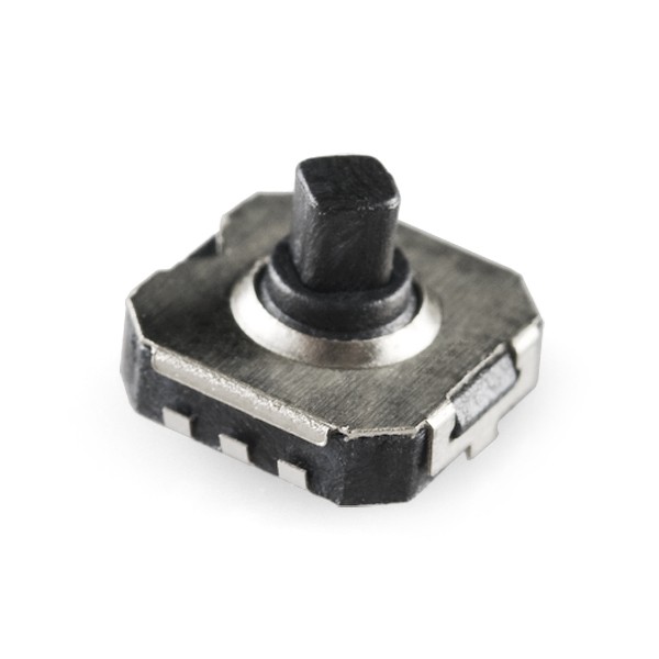
    To save place, the push button interface had to be removed. I am using a joystick-like interface in a very small package instead:

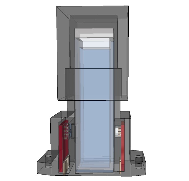
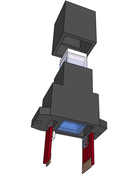
    X-ray view of the spectrophotometer:

    Partly routed shield:

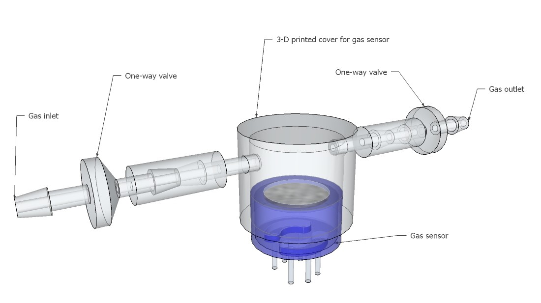
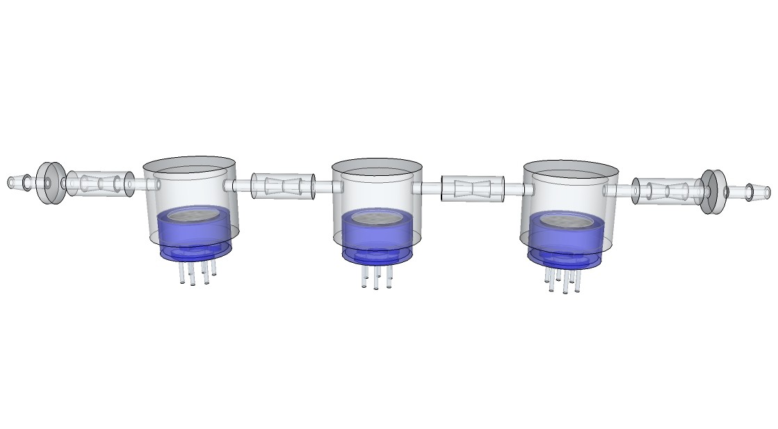
    One reason why I am using a respirator- half-mask for the respiration rate sensor is that I am able to do a analysis of the exhalation gases at the same time. This can be done by one or more common available MQ-series gas sensors, which are attached to 3-D printed gas chambers with a predefined volume:

  • Spectrophotometer

    M. Bindhammer05/21/2015 at 12:18 2 comments

    I should have thought about the Beer-Lambert Law earlier!

    \color{White} \large A_{\lambda}=\lg \frac{I_{0}}{I_{1}}=  \varepsilon_{\lambda} \times c \times lwhere

    • A: Absorbance or optical density OD of the wave length λ
    • I_0: Intensity of light that is incident on the sample [W·m^(−2)]
    • I_1: Intensity of light that is transmitted by the sample [W·m^(−2)]
    • ε: Molar extinction coefficient of the wave length λ [L·mol^(–1)·cm^(–1)]
    • c: Concentration [mol/L]
    • l: Length of the light path through the sample, usually 1 cm

    Spectrophotometers are commonly used to measure the concentration of a solution from its light absorbing properties. Some other examples of how they are used include:

    • Water quality - Turbidity, chlorine content, pH, water hardness, phosphate content etc
    • Microbial population growth - Turbidity of a microbial culture over time
    • Enzyme kinetics - Activity of an enzyme over time

    For RGB spectrophotometry we can use a RGB LED and the TCS3200 color sensor, which output is a square wave (50% duty cycle) with frequency directly proportional to light intensity.

    Proposed design, directly mountable on a PCB (complete copper fill without traces on both layers of the board in the area of the cuvette bottom to avoid exposure to light through the PCB):

    As initially mentioned one use of the spectrophotometer is to determinate microbial population growth. How we do that? Let's start with a exponential bacteria growth model. Let donate the increase in cells numbers ΔN per time interval Δt, then this ratio is proportional to the actual number of cells N. If for example a population of 10000 cells produces 1000 new cells per hour, a 3 times bigger population of the same microorganism will produce 3000 new cells per hour.

    \color{White} \large (1)~ \frac{\Delta N}{\Delta t}    \sim NWritten as a differential:

    \color{White} \large (2)~\frac{dN}{dt} \sim NUsing a proportionality factor μ < 0, which is called specific growth rate, yields to the first-order ordinary differential equation:

    \color{White} \large (3)~\frac{dN}{dt} = \mu \times N Separating the variables

    \color{White} \large (4)~\frac{dN}{N} = \mu \times dtIntegrating both sides

    \color{White} \large (5)~  \int  \frac{1}{N}~dN = \int \mu~dt\color{White} \large (6)~\ln(N) = \mu \times t + CDetermining the integration constant C using the initial condition t = 0:

    \color{White} \large (7)~ \ln(N_{0}) = \mu \times 0 + C = CSubstituting C in equation (6):

    \color{White} \large (8)~ \ln(N) =  \mu  \times t +  \ln(N_{0})Solving for N:

    \color{White} \large (9)~N = N_{0} \times e^{\mu  \times t}Let donate the generation time tg, where exactly

    \color{White} \large N = 2 \times N_{0}

    the equation (8) yields

    \color{White} \large (10)~ t_{g} = \frac{\ln(2)}{\mu}

    Now, the optical density or in this case more correctly the turbidity is directly proportional to the cell density. However, the proportionality between the optical density OD and the cell density exists only for OD ≤ 0.4.

    The cell density [cells/mL or cells/L] is given by

    \color{White} \large (11)~cell~density =  \frac{N_{sample}}{V_{sample}} =  \frac{N}{V}where N_sample is a proportion of the total cell number N and V_sample a proportion of the total culture volume V.

    Hence, equation (9) can be written as

    \color{White} \large (12)~\frac{N}{V} =  \frac{N_{0}}{V} \times e^{\mu  \times t} =  \frac{N_{0_{sample}}}{V_{sample}} \times e^{\mu  \times t}Using a proportionality factor a equation (11) yields

    \color{White} \large (13)~ \frac{N_{sample}}{V_{sample}} = a \times ODOnce the proportionality factor a is determined, we can calculate the cell density from any measured OD.

    If we just want to calculate the specific growth rate μ of the bacterium, we don't need a proportionality factor at all. Let donate OD_0 as the optical density at t = 0, then

    \color{White} \large (14)~OD=OD_{0}  \times e^{\mu \times t}Solving for μ:

    \color{White} \large (15)~  \mu= \frac{\ln \big(\frac{OD}{OD_{0}}\big)}{t}

  • LOC build

    M. Bindhammer05/16/2015 at 07:04 0 comments

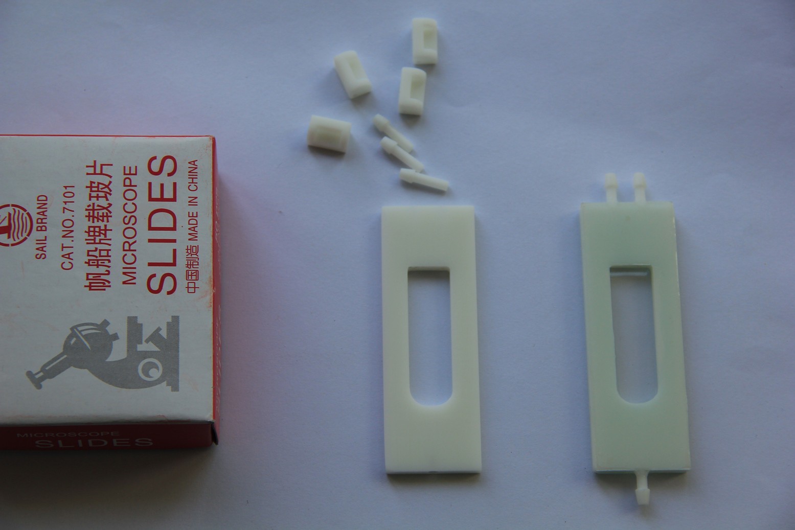
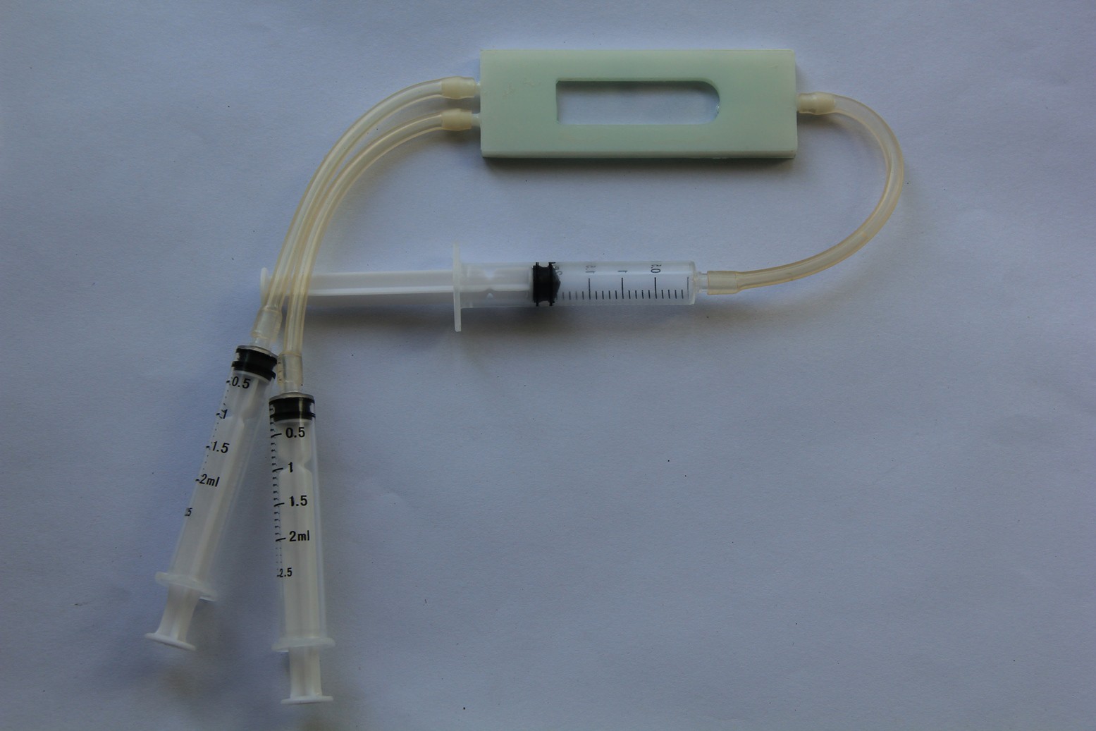
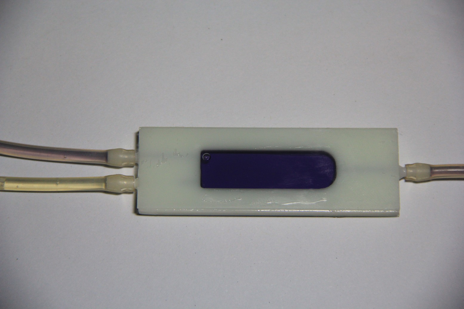
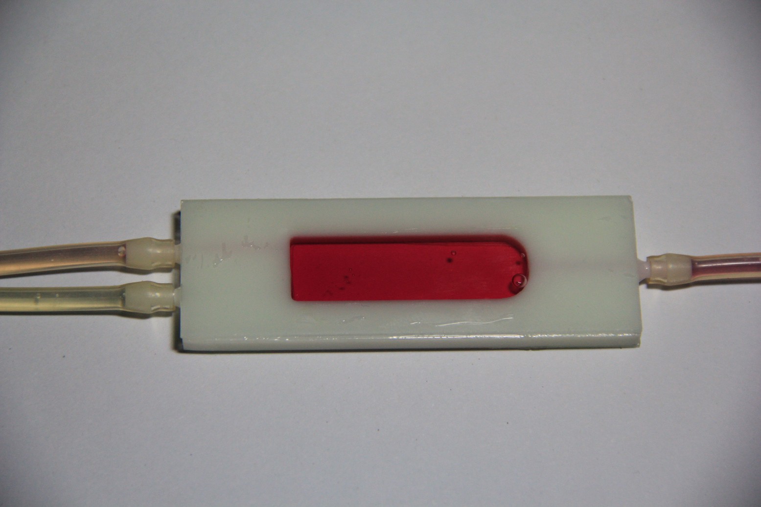
    Microscope slides, 3-D printed parts and the finished test-tube-shaped micro reaction chamber. 2-component 5-minutes epoxy resin adhesive has been used to glue the microscope slides and nipples in place:

    Leakage test (pass):

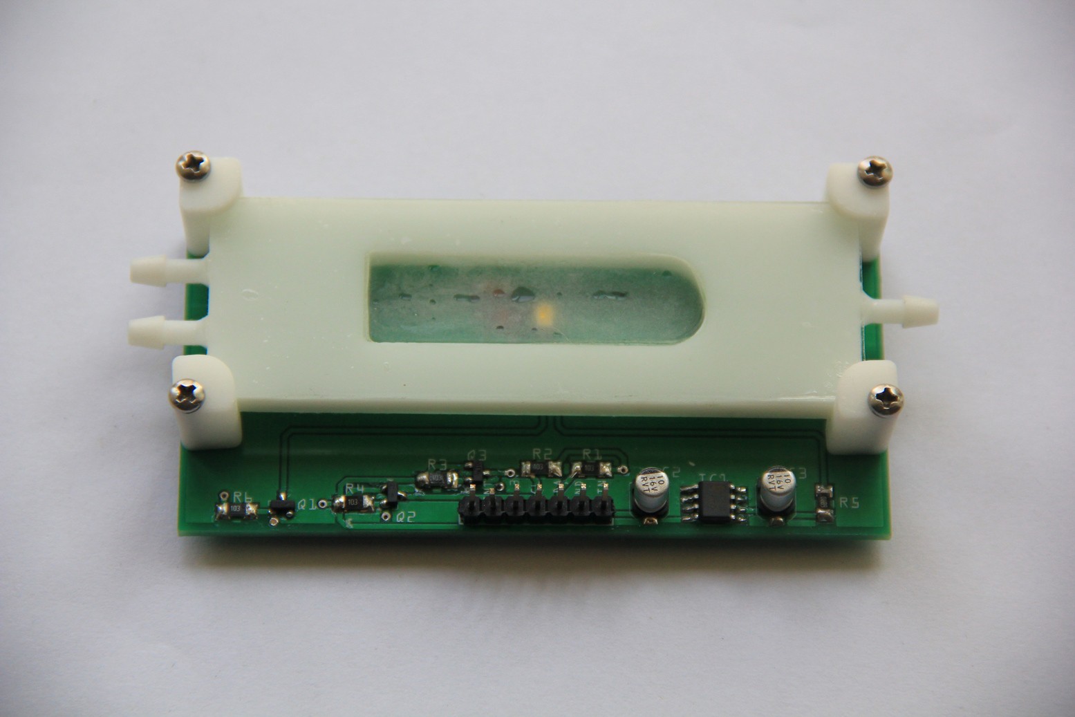
    Populated PCB:

    Reaction chamber attached:

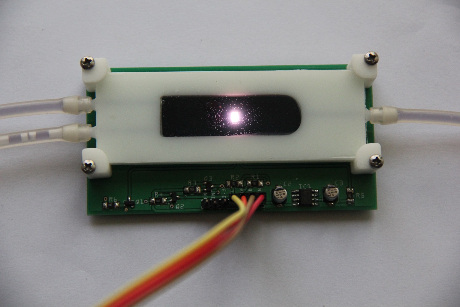
    Testing the LoC:

    For the first experimental demonstration of the LoC I have used red cabbage indicator. The pH look-up table for the kNN algorithm below was obtained via Color Cop and this image, but initial tests of the TCS34725 color sensor showed that it does not output a reliable RGB color model. I will probably use the raw red/green/blue/clear channel data and work in a 4-dimensional Euclidean space instead. Means also I need to obtain the look-up table for the kNN algorithm by an empirical approach.

    pH measurement of urine for instance provides information about the acid-alkali balance in a patient and helps to identify substances that are present in the urine. Maybe other household chemicals or natural chemicals like Cyanidin for pH could be used to test urine for Leukocytes, Glucose (Benedict's reagent ?) as a substitution for urine test strips.

    pH

    1

    2

    3

    4

    5

    6

    7

    8

    9

    10

    11

    12

    Color

    R

    239

    240

    240

    229

    213

    181

    107

    89

    70

    13

    2

    191

    G

    77

    76

    100

    124

    158

    142

    124

    129

    124

    125

    138

    216

    B

    52

    101

    163

    191

    213

    207

    196

    191

    184

    165

    134

    0

    Neutral red cabbage indicator (2 ml):

    Acetic acid 5% v/v (1 ml) added:

View all 18 project logs

  • 1
    Step 1
    Send the Gerber files to your favorite fab house. Any PCB manufacturer will accept Gerber formatted design files. Order at least two or three pieces in case you mess one PCB up.


  • 2
    Step 2

    Populate the board. You should have some experience with SMD soldering. If not I suggest this tutorial. Start with the micro SD card socket, continue with the IC's, discrete SMD components like resistors, capacitors, diodes and LED's, then solder the electrolytic capacitors, the MPXV4006GP, the SMD piezo buzzer, the audio jack, the SMD RESET push-button and the coin cell battery holder. Some components like the LED's have no markings on the package to indicate polarity so you'll need to take care when placing them.

    Thru-hole components like the MLX90614, the female pin header for the OLED, the trimmer, the mini push-buttons and the crystal for the RTC will be soldered at the end. Use a piece of heat shrink to insulate the body of the crystal.

    Next, place the male pin headers into the Arduino Mega board. This will make sure that the headers are perfectly lined up. Make sure the Arduino Mega is not powered or plugged in to USB! Place the medical tricorder shield on top of the Arduino Mega, making sure that all the headers line up nicely. Solder in each pin of the headers.

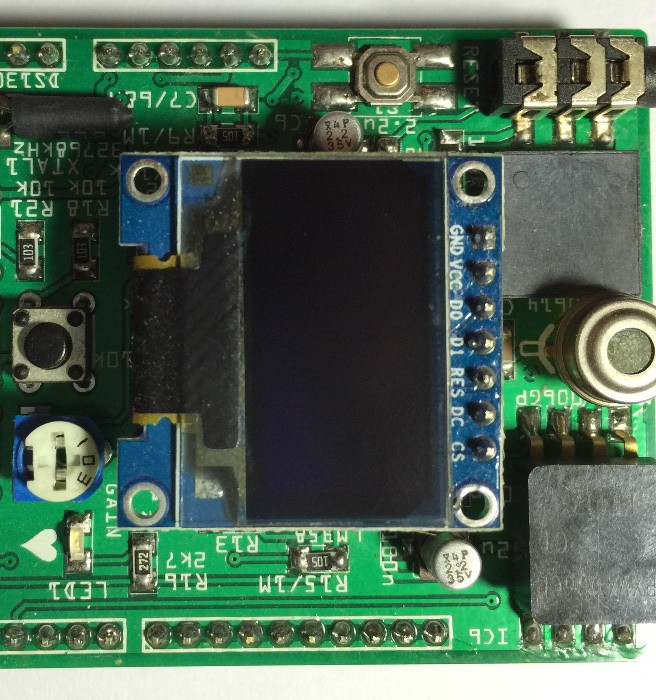
    Next, start by placing a 7-pin piece of header with the long ends down for the OLED into the female pin header on the shield for stability. Place the OLED on top so all the short ends of the header stick thru the header pads. Solder each of the 7 pins to the 7 pads.

    Finally plug in a fresh CR1220 coin cell battery to power up the RTC for the next several years and a suitable FAT16 or FAT32 formatted micro SD card for data logging!

  • 3
    Step 3

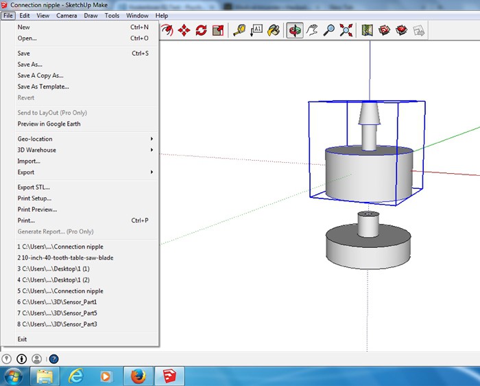
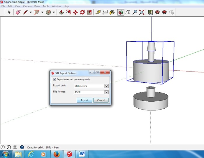
    Open connection nipple 3-D drawing with Sketchup 2014. Select the first part. Then click on the drop down menu for 'File' and select 'Export STL...'. When the 'STL Export Options' window opens, select 'Export selected geometry only', 'Export unit: Millimeter' and 'File format: ASCII'. Save the STL file. Do the same with the second part.

    3-D print both parts (PLA) using highest possible settings regarding strength and quality, e.g. 90% infill, layer height 0.1mm.

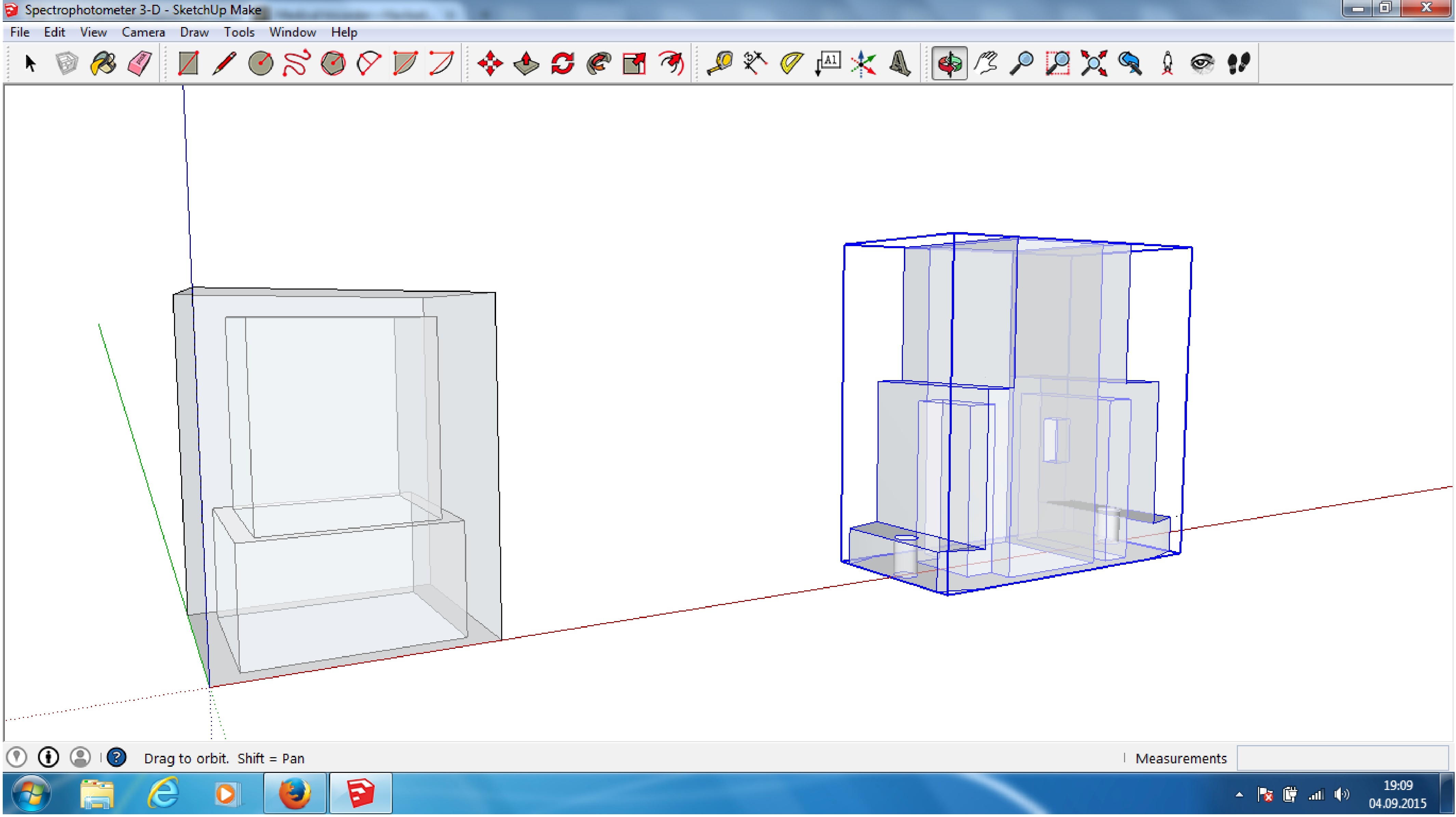
    Do the same with the spectrometer Sketchup model:

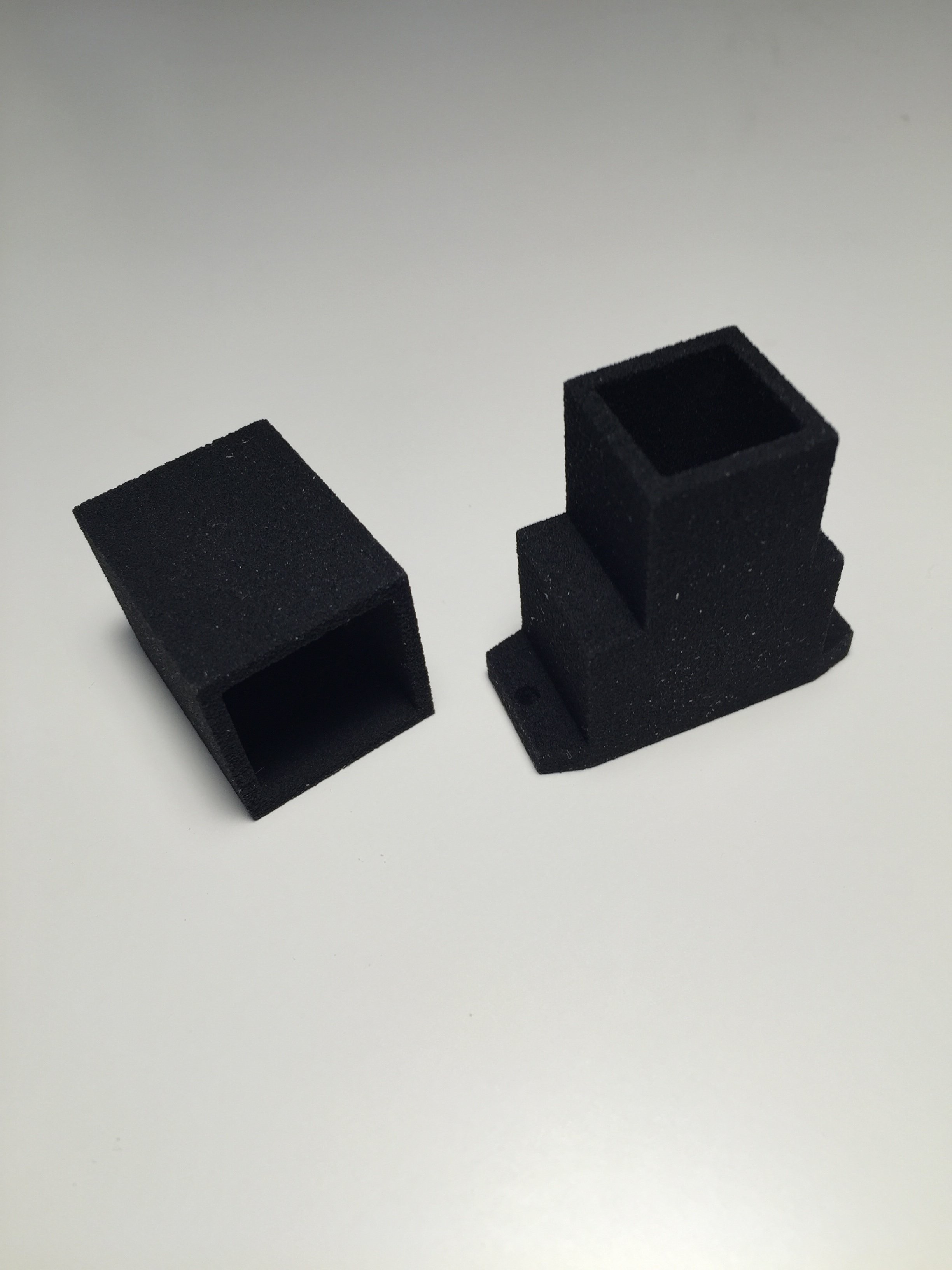
    Use a fab house who can do PMMA (black)/binding agent printing. Result should look like this:

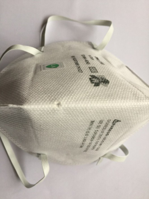
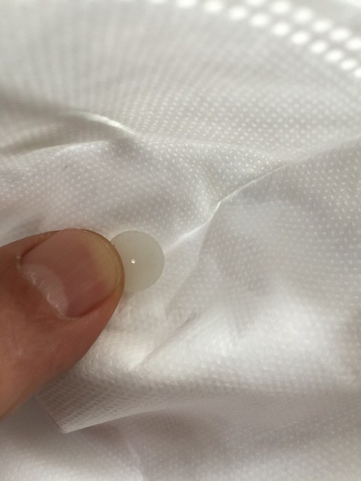
    Use a sharp object (scissors or screwdriver) and drill a small hole (Ø 3mm) into the middle of the mouth area of the disposable respirator- half-mask.

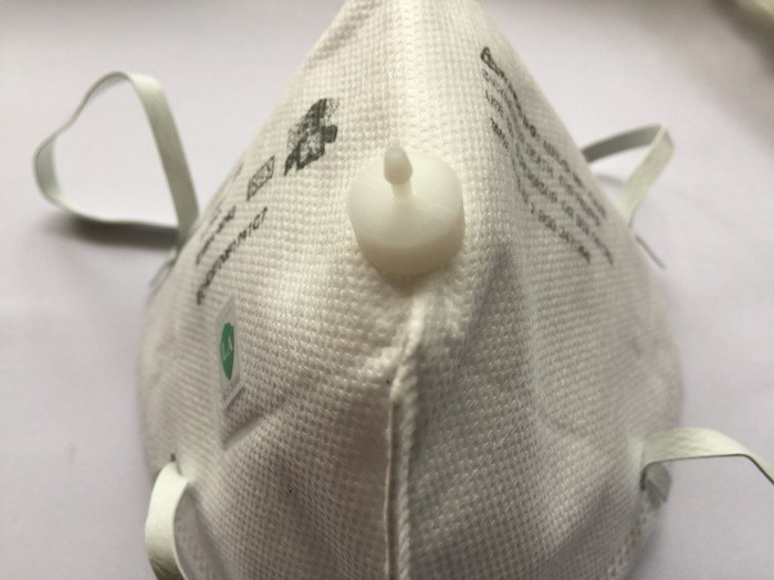
    Push the connection nipple counterpart from inside of the mask thru the hole. Make sure the feed-through of the counterpart isn't blocked by textile fibers of the mask.

    Press fit the connection nipple on the outer side of the mask.

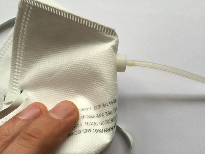
    Attach one end of the silicone hose to the mask, The hose shouldn't have a length greater than 0.5m.

    Attach the other end of the silicone hose to the pressure sensor on the shield.

    Mask, connection nipple and silicon hose are disposable devices. Never reuse, wash or disinfect them!

View all 4 instructions

Enjoy this project?

Share

Discussions

Barney Morrison wrote 01/28/2019 at 23:38 point

Any updates on this? I'd love to see you and Peter Jansen (who built this: https://hackaday.io/project/1395-open-source-science-tricorder) do another version together - I bet it could blow peoples minds! :-)

  Are you sure? yes | no

Tony wrote 12/06/2016 at 17:28 point

What is happening in 2016?

Can you post an updates?

Thank you very much!

  Are you sure? yes | no

M. Bindhammer wrote 01/13/2017 at 17:21 point

Will start a new project with an updated version of the medical tricorder soon...

  Are you sure? yes | no

Manoj Kumar wrote 01/16/2017 at 05:45 point

Awesome ! Eagerly waiting for the Rev 3 update files. Planning to build one for a science project . Thanks 

  Are you sure? yes | no

Kevin wrote 10/20/2015 at 18:17 point

Great project. Another option you could consider adding would be based on the project Chocometer project (https://hackaday.io/project/4642-chocometer) that can measure blood glucose levels without needing a blood sample.

  Are you sure? yes | no

DW-rocks wrote 08/28/2015 at 21:22 point

Wow great idea, thank you for sharing! There should be more people like you on earth.

  Are you sure? yes | no

Pure Engineering wrote 06/23/2015 at 16:20 point

check out my project. https://hackaday.io/project/4141-c12666ma-micro-spectrometer

you shoudl look at replacing the RGB sensor with a real spectrometer. 

  Are you sure? yes | no

M. Bindhammer wrote 06/23/2015 at 17:44 point

Thank you, Sir. I have checked your great project before. Only drawback is the price of that neat little spectrometer :)

  Are you sure? yes | no

Alex Rich wrote 05/17/2015 at 17:14 point

All of your projects are insanely detailed, nice job!  The little LOCs are really neat things, can they be easily removed from your case?  How do you throw them away when done without taking everything apart?

  Are you sure? yes | no

M. Bindhammer wrote 05/17/2015 at 22:54 point

Thank you, Sir.

You're right. I was thinking of a kind of snap in design for the LoC later. Currently I am researching what kind of chemical reactions could take place and what kind of sensors I could use to observe them.

  Are you sure? yes | no

Alex Rich wrote 05/18/2015 at 00:51 point

Touche, the issues I am harping on are low down on your list!  Keep it up, really impressed with all of your projects, especially the flagrant use of equations on your logs to explain the finer points of probability, etc.  Very interesting.

  Are you sure? yes | no

bdk6 wrote 04/03/2015 at 13:01 point

Really nice idea.  This could be very useful!

  Are you sure? yes | no

Russell Cameron wrote 04/03/2015 at 12:54 point

Great stuff Markus! Makes me want to get sick so i can try it out :P

  Are you sure? yes | no

M. Bindhammer wrote 04/03/2015 at 13:15 point

I'll send you a virus...Common cold or flue?

  Are you sure? yes | no

Andrew Starr wrote 10/11/2015 at 09:58 point
Don't worry, the virus will find him :)

  Are you sure? yes | no

Similar Projects

Does this project spark your interest?

Become a member to follow this project and never miss any updates