agp.cooper
-
Star Observation Code
03/22/2018 at 01:29 • 4 commentsIn the Beginning
In the beginning I was going to use "star observation" code but I was attracked to the direct sunrise/sunset "latitude" code. Why not, it is what is presented as the "solution" on all the Internet sites I visited.
The star obsevation code is more general and is based on a graphical iterative method. I wrote some code for my programmable calculator 35 years ago for it.
The problem with the latitude code is that it assumes the Declination and Right Ascension are constant. They are not, so it is not very accurate. It can be fixed but it is not a very tidy solution (just average the noon and midnight estimates).
Here is my version of the latitude and longitude codes:
double latitude(double SunRise,double SunSet,double Alt,double Dec) {
  double DL,A,B,C,D,U,V,Lat;

  DL=SunSet-SunRise;
  A=tan(radians(Dec));
  B=cos(radians(7.5*DL));
  C=sin(radians(Alt))/cos(radians(Dec));
  D=sqrt(A*A+B*B);
  if (fabs(C)<=D) {
    U=degrees(asin(B/D));
    V=degrees(asin(C/D));
    Lat=V;
    if (DL>0) Lat=V-U;
    if (DL<0) Lat=V+U;
    if (Dec<0) Lat=-Lat;
  } else {
    Lat=0.0;
  }
  return Lat;
}
And:JD=J2000(Year,Month,Day); SunData(JD,(Sunrise+Sunset)/2.0-LTC,&RA,&Dec); Lat=latitude(Sunrise,Sunset,Alt,Dec); GST=GMST(JD,(Sunrise+Sunset)/2.0-LTC); Lon=15.0*(RA-GST); if (Sunrise>Sunset) Lon=fmod(Lon-180,180);
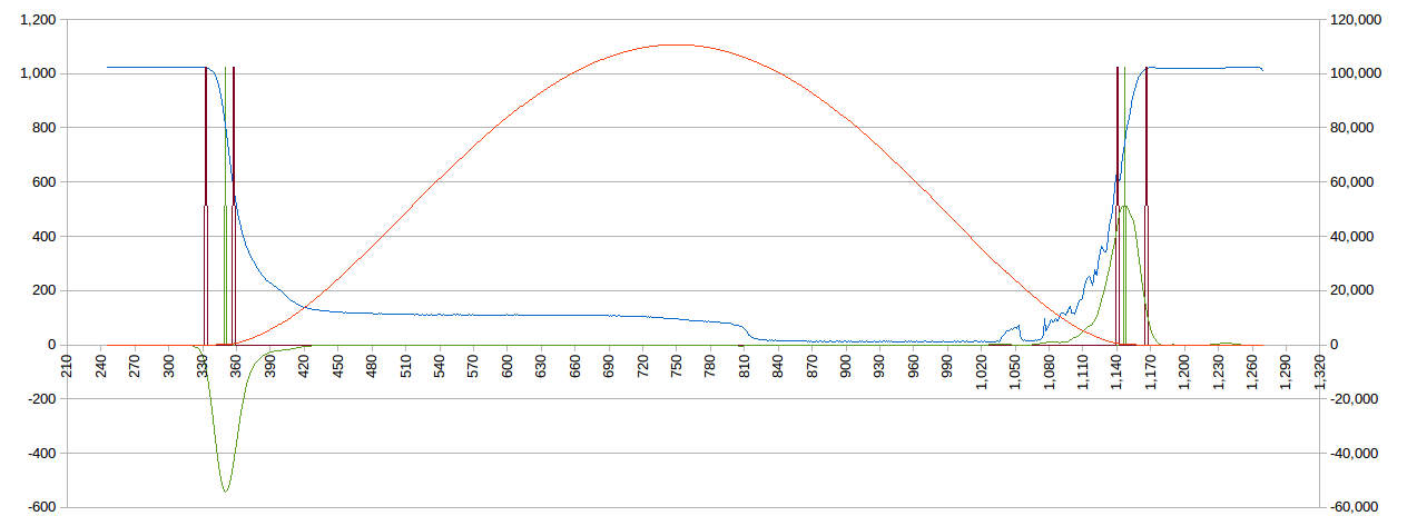
If you use this code with exact sunrise and sunset data you get:![]()
And:
![]()
The star observation code is more general:
void StarObs(float RA1,float Dec1,float Alt1,float UT1,float RA2,float Dec2,float Alt2,float UT2,float *Lat,float *Lon)
{
  float P1,P2,U1,U2,V1,V2,X0,Y0,LHA1,LHA2,EstLat,EstLon;
  EstLat=radians(*Lat);
  EstLon=radians(*Lon);
  RA1=radians(RA1*15.0);
  Dec1=radians(Dec1);
  Alt1=radians(Alt1);
  LHA1=radians(UT1*15.0);
  RA2=radians(RA2*15.0);
  Dec2=radians(Dec2);
  Alt2=radians(Alt2);
  LHA2=radians(UT2*15.0);
  do {
    P1=asin(sin(Dec1)*sin(EstLat)+cos(Dec1)*cos(EstLat)*cos(EstLon+LHA1-RA1));
    P2=asin(sin(Dec2)*sin(EstLat)+cos(Dec2)*cos(EstLat)*cos(EstLon+LHA2-RA2));
    U1=(P1-Alt1)*cos(Dec1)*sin(EstLon+LHA1-RA1)/cos(P1);
    U2=(P2-Alt2)*cos(Dec2)*sin(EstLon+LHA2-RA2)/cos(P2);
    V1=(Alt1-P1)*(sin(Dec1)-sin(EstLat)*sin(P1))/cos(EstLat)/cos(P1);
    V2=(Alt2-P2)*(sin(Dec2)-sin(EstLat)*sin(P2))/cos(EstLat)/cos(P2);
    if (V1*U2!=U1*V2) {
      X0=((V1*V1+U1*U1)*U2-(V2*V2+U2*U2)*U1)/(V1*U2-U1*V2);
      Y0=((V2*V2+U2*U2)*V1-(V1*V1+U1*U1)*V2)/(V1*U2-U1*V2);
    } else {
      X0=0.0;
      Y0=0.0;
    }
    *Lat=*Lat+X0;
    *Lon=*Lon+Y0;

  } while ((fabs(X0)>0.000001)||(fabs(Y0)>0.000001));
  *Lat=degrees(EstLat);
  *Lon=degrees(EstLon);
Now there are two questions about the code. Is it robust and how good does the initial estimate need to be?
In my head (based on the algorithm) the initial estimates need to be within 90 degrees (i.e latitude). The reason is the code assumes the earth is flat so 90 degrees is basically infinity.
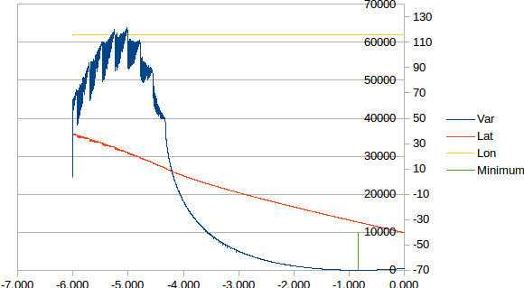
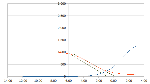
Is it robust? Tests say no! It did not work for altitudes less than about -4 degrees. It seems fine for the range of interest (i.e. -3 to 0 degrees):
![]()
The above plot show the star observation results:
- Red - Latitude
- Yellow - Longitude
- Green - The -0.833 degree altitude marker
- Blue - The variance of 16 sunrise/sunset measurements
Note the variance (Blue line) is zero for -0.833 degrees.
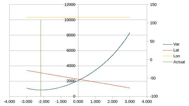
This plot is not quite what it seems. The data is exact for -0.833 degrees and the variance reflects the use of an incorrect altitude. The algorithm appears stable for altitudes "estimates" from -3 to 0 degrees.
From the plot the latitude is very sensitive to the altitude estimate.
The plot also indicates that for good qualitity data it is possible to reverse engineer the observations altitude.
The Longitude estimate hardly varies.
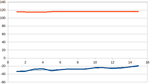
For uncorrected (for light levels) experimental data gave the following results:
![]()
Searching for the minimum variance gave:
- Lat: -35.816
- Lon: 115.408
Which is off 3 degrees in latitude (almost exact in longitude) but improvements are possible if lighting conditions are taken into account.
AlanX
-
Conclusion
03/05/2018 at 00:41 • 0 commentsConclusion
The logs need a clean up but otherwise I am done here.
My last roof reading was:
- Date (start) 4/Mar/18
- Sunset 19.0833
- Sunrise 5.8667
- Assumed altitude -4.3
- Latitude -32.25
- Longitude 115.75
- Error <2 km BUT this is for a calibrated altitude.
While the longitude is very close (within a minute of time), the altitude calibration is dependent on the site and varied between -2.5 (inside window) and -4.3 degrees (roof top). The difference in light levels between these two sites could not be much more extreme!
You could use the average sunlight intensity during the day to estimate the site altitude factor using the solver or a look up table. Without that the latitude accuracy is in the order of +/-5 degrees (+/-500 km). Worse if cloud affected. Still did anyone really believe you could get GPS accuracy with a LDR?
Update
I have been running the box for a week while I was on holidays. Upon return I downloaded the results:
![]()
As you can see the first results are about right but the latitude (-32) drifts off. Clearly I have have a coding error and have not updated the Day Number properly.
Fixed but there is something else wrong. The average is right but individual results scatter around the average in a rather predicable way.
Errors
In my mind there are three types of errors:
- Numerical (very hard to fix)
- Coding (i.e. mistakes)
- Conceptual (incorrect model or assumptions)
I check the various modules and but could not find any coding errors. Therefore I have made a bad assumption somewhere. All code has assumptions where we decide whether the model we ae using is fit for purpose.
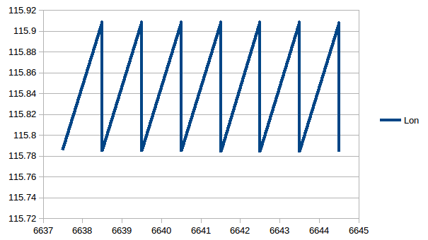
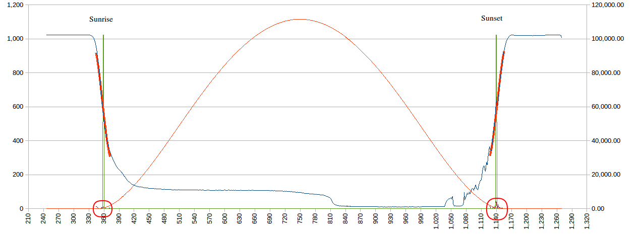
I created an exact set of sunrises and sunset times and test my code. The results indicate a problem. Here is the longitude oscillating around the true value (115.844):
![]()
And the equation:
- Lon = 15*(GMST-RA)
One solution is to take the average of the day and night estimates (the results are accurate as the errors appear to cancel). The error in the longitude is relatively easy to identify. The assumption that the average of the sunrise and sunset times is true noon is accurate enough for this application is false.
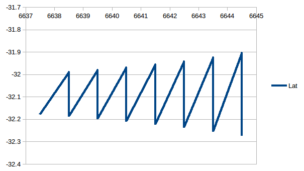
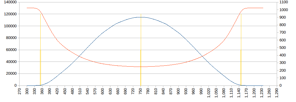
Here is the latitude oscillating around the true value (-32.09):
![]()
The error in the latitude is more complicated. Yes the average of the day and night estimates gives a very good results (i.e. the errors appear to cancel), feeding the RA and Dec for exact noon is not sufficient.
I need to dig a little deeper for a more exact equation.
AlanX
-
Full Circle
03/01/2018 at 08:35 • 0 commentsFull Circle
Its a bit like booze, you know its not good for you but you keep coming back for more!
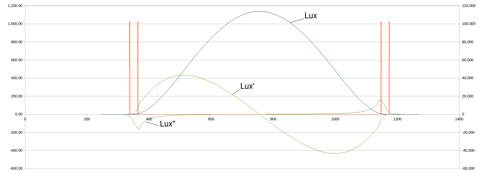
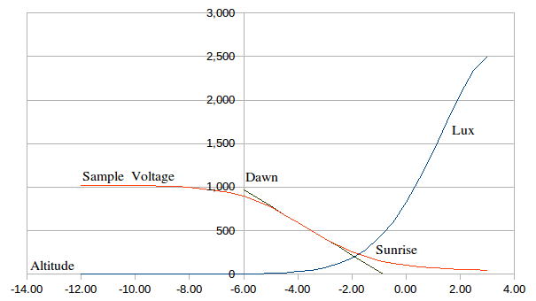
Anyway I am back looking at the sunrise/sunset transition. I was looking at the Lux curve and noting that the curve has a strong inflection (red circles) between twilight (i.e. dawn/dusk) and sunrise/sunset:
![]()
Anyway, here is the first and second derivative:
![]()
Now note the curve above is a "standard" curve not a measured curve. So the funny "hook" for Lux' is an artifact of the construction of the "standard" curve. What is interesting is Lux'' as it has a peak around sunrise and sunset. Now this is not surprising, the question is it practical to use this information?
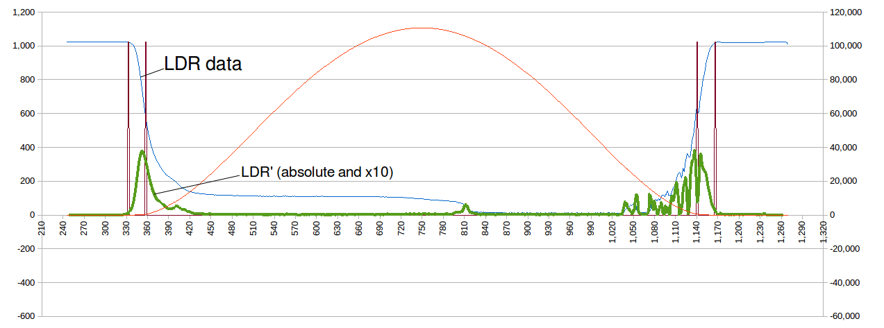
Okay here is some (old) measured data:
![]()
And yes it does look promising. Note, the green line is the first derivative of the LDR voltage (the magic on non-linear maths!). The noise on the right hand side can be filtered:
![]()
Well that looks very nice! The LDR peaks are very consistent. Some thought needs to be made to avoid false trips but it looks very promising.
Well it ran last night, if I cheat and adjust the assumed altitude for the best result (I can't calculate it at the moment as I do not have a calibrated the LDR sensor), I get:
- Year: 2018
- Month: 2
- Day: 28
- LTC: 8 hours
- Sampling frequency: 1 per minute
- Sunset: 19.0833
- Sunrise: 5.9000 (next day)
- Calibrated Altitude: -3.3 degrees
- Latitude: -32.027 (versus -32.090)
- Longitude: 115.747 (versus 115.844)
This is within 11 km of my true location and within accuracy of the sampling frequency.
So it the results are consistent, especally with cloudy conditions I have a great solution.
Another reading for today;
- 1/3/2018
- LTC: 8 hours
- Sunset: 19.0500
- Lat: -31.479
- Lon: 115.973
- 68.85 km away.
The box site was not the roof this time but in the middle of my back yard. A more typical/practical location.
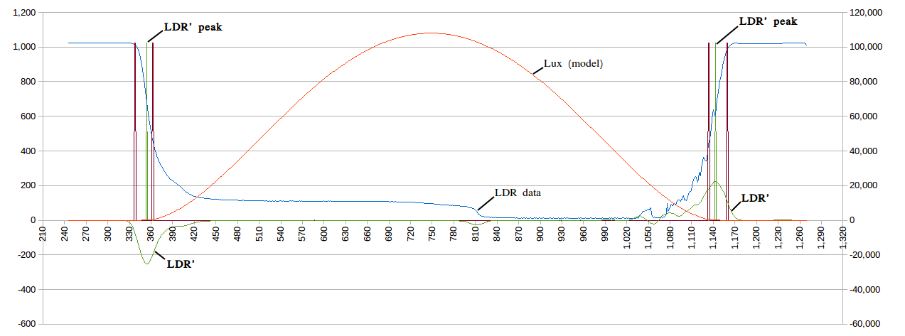
I reworked the filter (green) but more work is required:
![]()
I am currently using a threshold and a simple adjacent value test to determine a peak. I still need a threshold but better to use a sliding window to find the loacl maxima.
It seems as if the sunrise transition this morning was missed. The box site is shaded by a tree from the morning sunlight (unlike the roof position). With the new filter I can lower the threshold significantly. Currently the threshold is about 50% of the full sunlight range. With the new filter this can be reduced to 10% (or less).
New Code
Here is a sunset with the box placed in a window putting up with some ambient room light:
![]()
- Cyan curve is the calculated sunlight (Lux) level.
- The green markers are sunset and dusk.
- The blue curve is the ADC reading of the LDR.
- The red curve is the derivative of the ADC-LDR curve.
- The yellow curve is the window maximum calculations. It has a 31 minute window and is delayed 15 minutes.
- Back calculating the altitude of the derivative peak I get -2.5 degrees.
This looks quite promising. It will be interesting to see how much the peak altitude moves in full sunlight. Hopefully not much. I am expecting -3.3 degrees. I will probably have to look at a calibration factor based on the peak derivative value (a higher value should indicate a brighter sunset).
Some results (assuming -3.0 altitude):
- 18.9333, 0.0000, 120.0000
- 5.9000, -31.9239, 116.7482
Well it off 80 km, it means I am not going to escape a poorly selected site, assuming no coding errors. It is a poorly selected sight because the longitude is off which means the sunrise and sunset are not equal intensity (which I know for this site).
Magic
-
The Arduino is Not Playing Ball?
02/25/2018 at 14:21 • 0 commentsMemory Corruption
I have been getting EEPROM memory corruption. Usually at the same memory locations. I also know that the code modules work in isolation (if "jump stated") and are being called but I am not getting a successful run. So I am getting frustrated.
I wrote a bit of code to test the EEPROM and it passes. No problems! So what is going wrong?
In my code you cannot read/write addresses within a page going backwards without corruption (writing forward is okay) but the test code has no problems?
The only thing I found was that Wire.begin() has to be called before access the AT24Cxx library but not if the RTC library is called first. So I added a Wire.begin() to my code anyway.
One thing it could be is a stack/memory clash but I am not using that much RAM.
I have relook at the code so many times trying to workout what the problem is.
A relook at old but simpler code
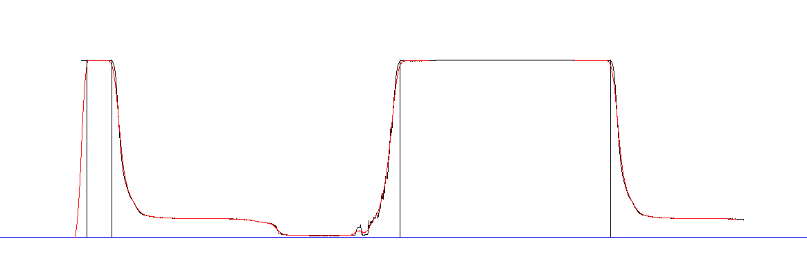
I relooked at the old code before jumping to the full daylight fitted model. Althought the intercept concept is flawed, it still can work. Here is some old work where I uses an exponential smoothing (blue) to trigger a cature widow (red horizonal bars). I also fitted a linear regression to the transition slope to "estimate" sunrise/sunset:
![]()
The problem with this idea is that the transition is a function of the light sensor (LDR) maths. Well not quite, if we look at the daylight (Lux) function (red) there is an inflection around sunrise/sunset (circlued):
![]()
I spend a day or two looking the transition area, trying different things (model, filters etc.). In the end Iiked ths one the best:
![]()
Here I heavily smoothed the data and then used a threshold to determine -6 degrees altitude. Here is another:
![]()
Here the code calculates latitude and longitude during the day and during the night. The black vertical lines are the calculated dawn/dusk markers. Note the false trigger during startup. From the two sets of data above the simple code works quite well. This code calculates on the fly and does not need the EEPROM.
For the code I looked at linear regression, quadratic regression, logistic regression, IIR LP, FIR LP, exponential, quadradic and cubic smoothing. In the end I used two passes of of a window smoother. A window or box smoother just averages a window (in this case 21) values (and used no weights).
With smoothed data I can reliably trip the twilight (i.e. dawn/dusk) marker with a threshold.
The threshold/altitude pair is calibrated for a setup, but once setup should be reasonably robust (to be investigated further). The current setup (dawn/dust) requires low night light levels.
Possible Problem with EEPROM
I had no problems with simplified version of the code that is less the menu, rotary encoder polling ISR and the Solver. I suspect that the polling ISR is causing problems with the Wire library.
The simplified version of the code is ready for a trial.
Sensor Sensitivity
I checked my sensor against a Lux sensor:
- 1020 ~10 Lux
- 600 ~250 Lux
- 6 ~66,000 Lux
The current threshold of 988 returns -6 degres alititude (i.e twilight or 3.4 Lux).
If I look at the Lux curve:
![]()
I should be targeting sunrise/sunset (red circle) rather than dawn/dusk. For the smoothing (lowpass filter) to work in my application I need to reduce the sensor sensitivity (especially if it is located outside). This will move the sunrise transition to the right and the sunset curve to the left. Currently the LDR load resistor is 22k so perhaps a value of 4k7 may be better.
Sunrise and sunset have light level around 400 Lux (40 Lux if heavily overcast) and twilight around 3.4 Lux.
Sensor Calibration
As sensor was not following the mathematics I developed from the datasheet, I took three measurements:
- Direct sunlight: 61k Lux and ADC=163
- Inside: 173 Lux and ADC=861
- Under a plastic box: 6 Lux and ADC=1019
Fitting a model to this data I got:
- Load Resistor: 1k (actual)
- LDR 110k
- LDR power factor 0.579
Based on this model the sunrise and sunset threshold (~400 Lux) should be ADC=779.
Lower than I would like but good enough for the time being. For low power I will need to redesign the sensor circuit, perhaps use the Lux sensor instead.
Anyway, the box is on the roof collecting a sunset and tomorrow a sunrise. Lets see how it goes.
Well, latitude was way off (all though in the right hemisphere) but longitude was spot on. With one minute samples the longitude accuracy (1/2 minute) is 10.67km, for my latitutde. I got 17.5 km (0.2 degrees).
I should do a proper LDR versus Lux calibration but I want to try an LED as Ted (https://hackaday.io/ted.yapo) suggested a while back. I am going to replace the rotary encoder with a simple push button as well.
Magic
-
PROJECT REBOOT
02/15/2018 at 06:14 • 0 commentsProject Reboot - A major Change Direction
I have given up on accurate estimation of sunrise (or dawn) and sunset (or dusk) directly from daylight measurements. It seems easy but it is not, and cloud cover blows you away!
Full Daylight Model Fitting
Okay thats the new path, fit the full daylight model. The solver was a major coding hurdle but it is done now. If I feed the solver calculated LDR readings (quantitized to be fair) it has no problems solving latitude and longitude directly to within a few km (and the average cloud factor). A few hundred metres if the LDR reading are not quantized). If the data has consistent light reduction due to cloud cover, then no problem. It cloud cover is inconsistent (between morning and afternoon) then it will be a problem, you can't have everything! A better cloud cover model can be used but that is an optimisation for later.
Although the TLS2591 would be ideal as it has higher resolution (16 bit) than the internal ADC (10 bit), the LDR and the internal ADC can be used. I calculate a 10k load resistor would be approprate (for my LDR). Here is the LDR ADC reading (red-right) versus Daylight (blue-left) Lux level used by my solver:
The solver is based on the Nelder-Mead "ameoba method", but any steepest descent solver will work fine. Here is the inner core of the function (i.e. minmising Error2), the input variables to be optimised are CloudFactor, Lat and Lon:Error2=0.0; for (i=0;i<SampleSize;i++) { LT=SampleData[i][0]/60.0; SampleVoltage=(double)SampleData[i][2]; // Determine GMST, RA and Dec GST=GMST(JD,LT-LTC); SunData(JD,LT-LTC,&RA,&Dec,&EoT); // Local Hour Angle and Altitude LHA=15.0*(GST-RA)+Lon; Alt=degrees(asin(sin(radians(Dec))*sin(radians(Lat))+cos(radians(Dec))*cos(radians(Lat))*cos(radians(LHA)))); // Daylight intensity (Lux) and Sensor Voltage Lux=DayLight(Alt)*(1.0-CloudFactor); SensorVoltage=floor(1023.0/(1.0+10000.0/20000000.0*pow(Lux,0.75))+0.5); //Calculate Least Square Fit error Error2=Error2+(SensorVoltage-SampleVoltage)*(SensorVoltage-SampleVoltage); }Okay back to the Box code to include the new solver.
Ported the code to the Box (Arduino) and a day of debugging. Using test data the Box reports a latitude within 30 km (longitude almost exact). No surprises that the latitude is off as it is the "hardest" to measure and calculate. Still using float, trials with double showed no improvement. The limitation is the "shallow bottom" of the search space and the effect of ADC quantisation.
I am using the sum of absolute values rather than sum of squares because (1) the sum range is too great for float (at least initially so not really an issue) and (2) I want less weight to cloud and ADC quantisation noise.
Interestingly enough if I use the square root of the absolute value then I get a very good result, within 1.3 km. I don't know if this is repeatable? Not convinced.
Next is to rework the menu and sample storage code.
Okay, the code has been rewritten and the Box is now collecting data. Hopefully no bugs.
First Data
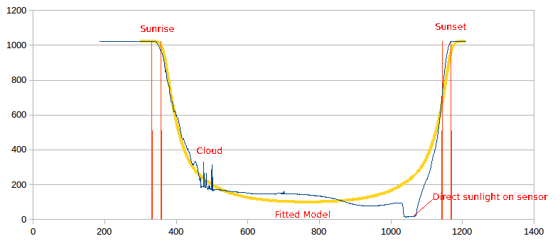
The first data was off by 400 km. Not a great result. I am also getting some data corruption, perhaps it is time for a new RTC module. Anyway here is what the data looked like:
![]()
The yellow line is the fitted model. In my mind it is a pretty good fit to the data (blue). The morning was cloudy and the afternoon clear. Also the sensor location is near a south-west facing window. The heel in the blue data would be direct sunlight on the sensor box in the afternoon. So okay, not the best box location. I could do much better.
Two parameter SunFactor
I reworked SunFactor for differences bewteen moring and afternoon sun light:
![]()
The fit is quite good and the positional error is down to 120 km. So really the next step is modifying the light sensor to be less sensitive to direct sunlight and putting the box in a better location.
The solver is semi-stable. It needs a better initial estimate than 0 degrees latitude to get going (reliably).
Fix the initial solver estimate by using the sunrise and sunset equations (as previuosly developed). The solver then improves these for variations in sunlight intensity (due to site and cloud cover effects).
Back to the transition model
Well, what can I say I am back looking at the twilight transition model! The full daylight model requires the sensor to me placed in a non-obstructed location. Not that easy, so I reworked the model:
![]()
The current location has a better balance between morning and afternoon sunlight but is still affected by direct sunlight in the mid-afternoon. I matched a model 15 minutes before and after sunrise/sunset (-4 to 2 degrees altitude). This time I only scaled the modelled LDR load resistor. The result was within 170 km of the true location.
Upon reflection on the model, it seems to be the right place as the Lux curve (red) has an identifiable inflection points (circled red), that are sunrise and sunset.
Clearly if I ensure sunrise and sunset are treated equally (by the box location) then I should get better results. I am going to put a diffuser over the sensor to see it that helps as well.
Added the pingpong diffuser. Took a while to workout how to do it:
![]()
Why a diffuser? Without a diffuser the sensor will read 100% when point at the source but ~0% when pointer perpendicular. This could be corrected in software but better if the sensor is omni-directional. The pingpong ball is about the best I could think off.
Magic
-
Useful references
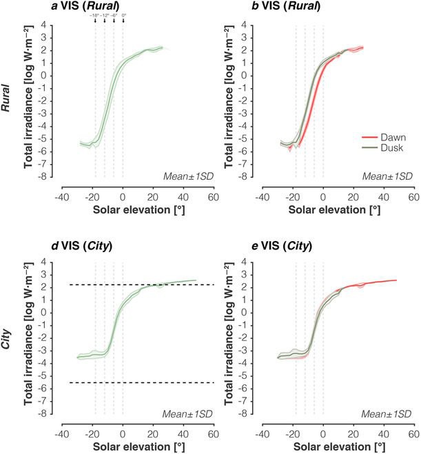
02/13/2018 at 05:44 • 0 commentsUseful references
I found this reference ("Variation of outdoor illumination as a function of solar elevation and light pollution") which has plots of dawn/dusk light intensity:
https://www.nature.com/articles/srep26756#f2
![]()
So there is a big difference between rural dawn and dusk (3 to 4 degrees!) but less for city dawn and dusk (about a degree). This will cause problems!
Another reference (http://stjarnhimlen.se/comp/radfaq.html) had a sun Lux data set covering 90 degrees down to -18 degrees altitude! For -6 degrees (civil twilight) the light level is 3.4 Lux. This number would for a clear night. For the range -12 to 3 degrees I fitted the following cubic:
Lux=10^(2.916+0.268942*Alt-0.03126*Alt^2-0.00156*Alt^3)
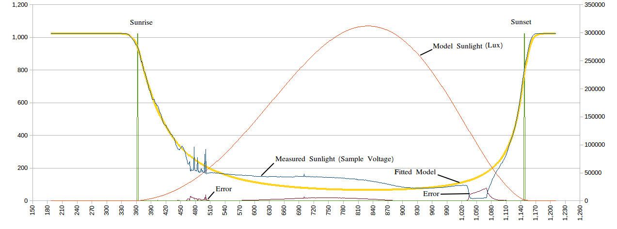
So now I can map Time, Altitude, Lux and Sample Voltage:
![]()
Notes:
- the linear regression only uses sample voltages between 400 and 700
- the assumed LDR dark resistance is 20M (I really should measure this!)
- the LDR load resistor is 1.2M
So two problems remain:
- the dawn/dusk offset
- non-ideal weather conditions
No solution to the dawn/dusk offset except to use a constant (guess).
Weather conditions
A 50% reduction in light levels is shown below:
![]()
This will cause problems as well.
Oh Slope!
I am coming to the conclusion that the slope is not that useful. In both cases the Lux level for the intercepts were the same (check the two graphs) so basically why bother! Again the slope like the inflection point is a function of the LDR maths. I should have picked this up when I was moving the curves left and right.
Where to now?
One option is to fit the entire daylight and twilight cycle. Entire curve will provide infromation on average/peak light levels. And I have a full model that I can fit.
AlanX
-
Sub-Systems
02/06/2018 at 02:37 • 0 commentsSub-Systems! What is that?
This project is the first project for me that has lots of necessary supporting sub-systems. They include:
- The LCD display
- The RTC (Real Time Clock)
- The AT24C32 (EEPROM)
- The rotary push button input device and polling code
- A menu system for:
- Setting the clock to local time
- Setting the local time correction (to Universal Time)
- Setting the LCD LED timeout
- Downloading the data
- Clearing stored data
- Checking the LDR
- Checking the results
- Dealing with power outages (restarting as if nothing happened).
- Setting the time automatically upon recompile.
- Storing the sample data and results.
- Processing the data.
- Displaying the results.
So it is a big deal to coordinate all these systems.
LCD display
The LCD library is very easy to use, the biggest difficulty is selecting the pins to use. Some pins have special functions such as interrupt, PWM, SPI etc. Some other types of display (that use SPI) have fixed pin requirements. The final selection for the pins was designed to be useful for both an LCD display with the typical 4 bit parallel interface, and an SPI type display such as the WaveShare E-Ink display.
For the LCD display:
- EN D7
- RS D8
- D4 D9
- D5 D10
- D6 D11
- D7 D12
- LED D13 (for the display)
For the SPI display:
- Busy D7 (Input)
- Rst D8 (Output)
- DC D9 (Output)
- CS D10 (SS)
- DIn D11 (MOSI)
- ----- D12 (MISO) - Not used
- Clk D13 (SCLK)
As the display is using the D13, I removed both the power and the built in LEDs from the Nano board.
Rotary encoder and push button input
There are different types of rotary encoders and they are not compatible! One type has one transition per detent (the stop position) and the other has two transitions per detent. The first type is the best to use. I am unfortunately using the other type.
Understanding the Rotary Encoder
- When you rotate the encoder clockwise then between detents, Pin A will change state before Pin B.
- When you rotate the encoder anti-clockwise then Pin B will change state before Pin A.
- When both pins have changed state then you have moved from one detent to the next detent (assuming the rotary encoder is of the first type).
- Now all you need to do is flag when both pins have changed state and use the the direction (flag) of the last pin to change state.
Got that? Okay here is the code:
  // Update Encoder Position
  lastPinA=testPinA;             // Save PinA
  lastPinB=testPinB;             // Save PinB
  testPinA=(PIND>>PinA)&1;       // Get PinA
  testPinB=(PIND>>PinB)&1;       // Get PinB

    if (testPinA!=lastPinA) {      // Change in PinA?
      flagPinA=true;               // Flag PinA has changed
      encoderDir=-1;               // Assume it is the last flag to change
    }
    if (testPinB!=lastPinB) {      // Change in PinB?
      flagPinB=true;               // Flag PinB has changed
      encoderDir=1;                // Assume it is the last flag to change
    }
    if (flagPinA&&flagPinB) {      // Both flags have changed
      EncoderPos+=encoderDir;
      flagPinA=false;              // Reset PinA flag
      flagPinB=false;              // Reset PinB flag
    }
(Don't you love the random colours the editor gives to your code!)
Polling or an Interrupt Service Routine (ISR)
There are many option to "connect" the rotary encoder to your code (as above). In my case I used one of the two "unused" interrupt vectors associated with the Timer0 for polling. Basically rather than use an interrupt monitoring a change on the pins, I "poll" the pins using the millis() timer. Timer0 is used for millis(), delay(), micros(), delayMicroseconds(), and PWM output on pins 5 and 6. So providing you don't need to use PWM of pin 5 or Pin 6, you can use the interrupt vectors ISR(TIMER0_COMPB_vect) or ISR(TIMER0_COMPA_vect).
The main reason for polling was that I would have needed three level change interrupts. One for Pin A, one for Pin B and one for the (push button) Switch, and I would still need a timer for debounce of the switch. In the case of polling, these can all be combined into one ISR. Here is the rest of the code:
/* ROTARY ENCODER AND PUSH BUTTON POLLING CODE */
#define PinA 2
#define PinB 3
#define SW   4
volatile bool UpdateSwitch=false;
volatile byte Switch=HIGH;
volatile int EncoderPos=0;
ISR(TIMER0_COMPB_vect) {
  static byte testPinA=(PIND>>PinA)&1;
  static byte testPinB=(PIND>>PinB)&1;
  static byte lastPinA=LOW;
  static byte lastPinB=LOW;
  static bool flagPinA=false;
  static bool flagPinB=false;
  static bool encoderFlag=true;
  static int encoderDir=0;
  static byte testSW=HIGH;
  static byte statusSW=HIGH;
  static byte cntSW=0;

  // Update Encoder Position
  lastPinA=testPinA;             // Save PinA
  lastPinB=testPinB;             // Save PinB
  testPinA=(PIND>>PinA)&1;       // Get PinA
  testPinB=(PIND>>PinB)&1;       // Get PinB

  // This rotary encoder updates twice per detent!
  if ((testPinA==HIGH)&&(testPinB==HIGH)) encoderFlag=true; // Encoder is in detent
  if ((testPinA==LOW)&&(testPinB==LOW)) encoderFlag=false;  // Encoder is between detents
  if (encoderFlag) {                                        // First transition (leaving detent) only
    if (testPinA!=lastPinA) {      // Change in PinA?
      flagPinA=true;               // Flag PinA has changed
      encoderDir=-1;               // Assume it is the last flag to change
    }
    if (testPinB!=lastPinB) {      // Change in PinB?
      flagPinB=true;               // Flag PinB has changed
      encoderDir=1;                // Assume it is the last flag to change
    }
    if (flagPinA&&flagPinB) {      // Both flags have changed
      EncoderPos+=encoderDir;
      flagPinA=false;              // Reset PinA flag
      flagPinB=false;              // Reset PinB flag
    }
  }

  // Update switch with 20 ms debounce
  testSW=(PIND>>SW)&1;
  if (testSW!=statusSW) {
    statusSW=testSW;
    cntSW=20;
  }
  if (cntSW>0) {
    cntSW--;
    if (cntSW==0) {
      Switch=statusSW;
      UpdateSwitch=true;
    }
  }
}
Dealing with two transitions per detent
The code below deals with two transitions per detent by only accepting the one transition per pin. Just comment out these two line if you have a rotary encoder of the first type:
  // This rotary encoder updates twice per detent!
  if ((testPinA==HIGH)&&(testPinB==HIGH)) encoderFlag=true; // Encoder is in detent
  if ((testPinA==LOW)&&(testPinB==LOW)) encoderFlag=false;  // Encoder is between detents
The push button switch
The push button code looks for a change in state and starts a countdown timer. Upon timeout it sets the switch flags:
  // Update switch with 20 ms debounce
  testSW=(PIND>>SW)&1;
  if (testSW!=statusSW) {
    statusSW=testSW;
    cntSW=20;
  }
  if (cntSW>0) {
    cntSW--;
    if (cntSW==0) {
      Switch=statusSW;
      UpdateSwitch=true;
    }
  }
What is inside the box?
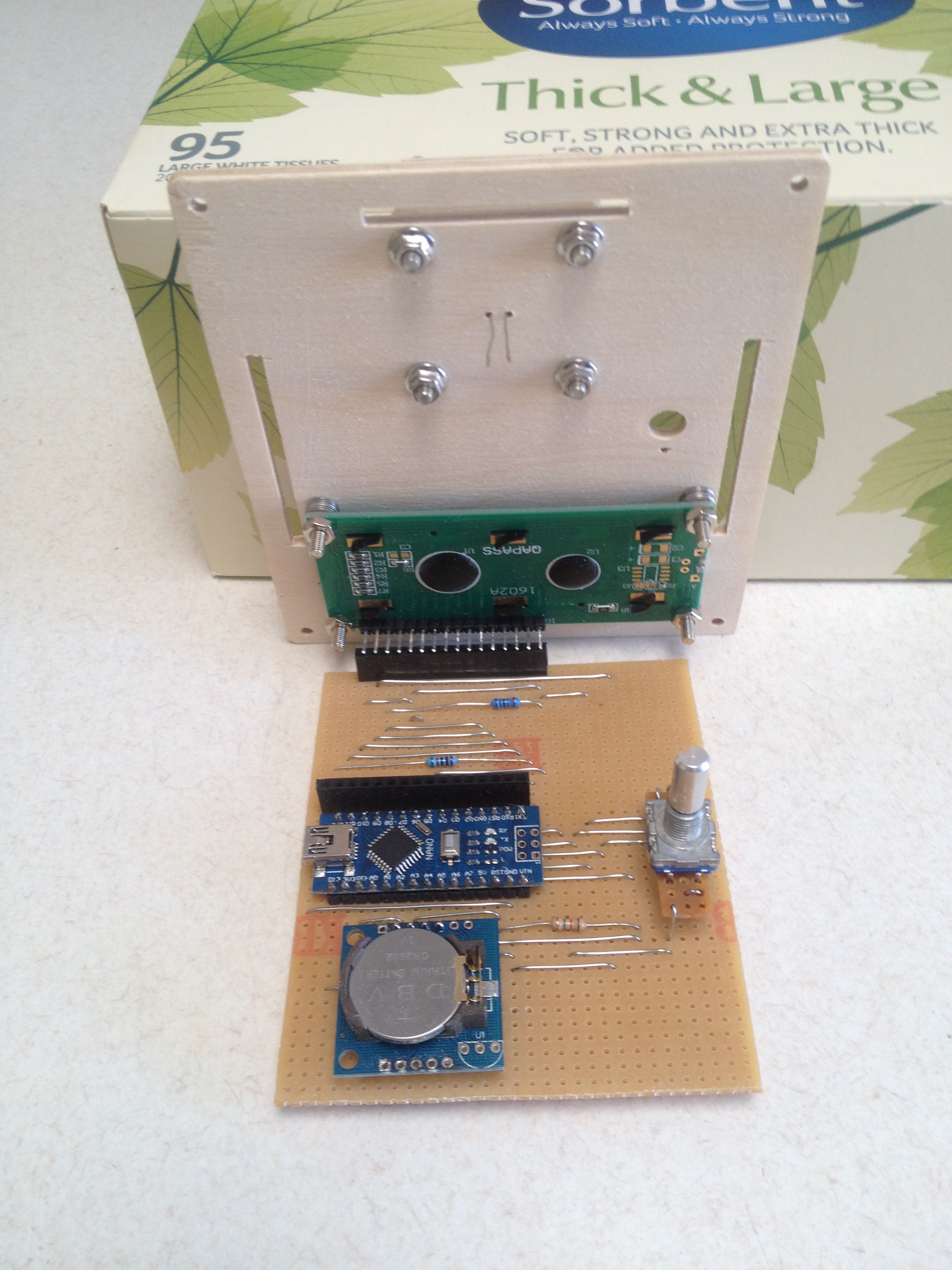
I replaced the LDR load resistor so while the box was open, here is a snap shot:
![]()
The Menu System
The menu system has been designed to be very simple to update or expand. I have put together a demostration using the rotary encoder to control the blink rate of the builtin LED:
/*
  Rotary Encoder Blink
  ====================
  Written by Alan Cooper (agp.cooper@gmail.com)
  This work is licensed under the
  Creative Commons Attribution - Non Commercial 2.5 License.
  This means you are free to copy and share the code (but not to sell it).
  Also it is good karma to attribute the source of the code.
*/

/*
  ROTARY ENCODER AND PUSH BUTTON POLLING CODE
    Uses Timer0 without upsetting millis(), delay() etc.
    You lose PWM on Arduino/Nano pin 5 (D5).
    Don't turn the encoder too fast as it will not work!
*/
#define PinA 5
#define PinB 4
#define SW   3
volatile bool UpdateSwitch=false;
volatile byte Switch=HIGH;
volatile int EncoderPos=0;
ISR(TIMER0_COMPB_vect) {
  static byte testPinA=(PIND>>PinA)&1;
  static byte testPinB=(PIND>>PinB)&1;
  static byte lastPinA=LOW;
  static byte lastPinB=LOW;
  static bool flagPinA=false;
  static bool flagPinB=false;
  static bool encoderFlag=true;
  static int encoderDir=0;
  static byte testSW=HIGH;
  static byte statusSW=HIGH;
  static byte cntSW=0;

  // Update Encoder Position
  lastPinA=testPinA;             // Save PinA
  lastPinB=testPinB;             // Save PinB
  testPinA=(PIND>>PinA)&1;       // Get PinA
  testPinB=(PIND>>PinB)&1;       // Get PinB

  /* If your encoder jumps in steps of two, uncomment this code */
  // if ((testPinA==HIGH)&&(testPinB==HIGH)) encoderFlag=true; // Encoder is in detent
  // if ((testPinA==LOW)&&(testPinB==LOW)) encoderFlag=false;  // Encoder is between detents

  if (encoderFlag) {             // First transition (leaving detent) only
    if (testPinA!=lastPinA) {    // Change in PinA?
      flagPinA=true;             // Flag PinA has changed
      encoderDir=-1;             // Assume it is the last flag to change
    }
    if (testPinB!=lastPinB) {    // Change in PinB?
      flagPinB=true;             // Flag PinB has changed
      encoderDir=1;              // Assume it is the last flag to change
    }
    if (flagPinA&&flagPinB) {    // Both flags have changed
      EncoderPos+=encoderDir;
      flagPinA=false;            // Reset PinA flag
      flagPinB=false;            // Reset PinB flag
    }
  }

  // Update switch with 10 ms debounce
  testSW=(PIND>>SW)&1;
  if (testSW!=statusSW) {
    encoderFlag=true;            // Reset encoder flag (precaution)
    statusSW=testSW;
    cntSW=10;
  }
  if (cntSW>0) {
    cntSW--;
    if (cntSW==0) {
      Switch=statusSW;
      UpdateSwitch=true;
    }
  }
}


/* MENU SET UP */
enum NoYes {N,Y,A};
enum MenuLevel {Top,Menu,Set};
enum MenuItem       { Exit_Menu  , Delay_MS  };
char* menuName[]   ={"Exit Menu ","Delay ms "};
char menuNumeric[] ={         N  ,        Y  };
int menuValue[]    ={         Y  ,      500  };
int menuValueMin[] ={         N  ,       10  };
int menuValueMax[] ={         Y  ,    32750  };
int menuValueStep[]={         Y  ,       10  };
int menuSize=sizeof(menuName)/sizeof(char*);
int menuLevel=Menu;

// Our variable to set the delay period
unsigned long intervalMillis=1000;

bool processMenu(void) {
  static int lastPos=Exit_Menu;
  static int lastMenuLevel=Top;

  // Disable polling
  TIMSK0&=~(1<<OCIE0B);

  // Pre-empt menu level display
  if (menuLevel!=lastMenuLevel) {
    lastMenuLevel=menuLevel;
    if (menuLevel==Menu) {
      Serial.print("Menu: ");
      Serial.print(menuName[EncoderPos]);
      if (menuNumeric[EncoderPos]==Y) {
        Serial.println(menuValue[EncoderPos]);
      } else {
        if (menuValue[EncoderPos]==N) {
          Serial.println("N");
        } else {
          Serial.println("Y");
        }
      }
    } else if (menuLevel==Set) {
      Serial.print("Set:  ");
      Serial.print(menuName[lastPos]);
      if (menuNumeric[lastPos]==Y) {
        Serial.println(menuValue[lastPos]);
      } else {
        if (menuValue[lastPos]==N) {
          Serial.println("N");
        } else {
          Serial.println("Y");
        }
      }
    }
  }

  // If push button pushed toggle menu level
  if (UpdateSwitch) {
    UpdateSwitch=false;
    if (Switch==LOW) {
      // Re-enter menu if button pushed (for long enough)
      if (menuLevel==Top) {
        menuLevel=Menu;
        lastMenuLevel=Top;
        lastPos=Exit_Menu;
        EncoderPos=Exit_Menu;
        menuValue[Exit_Menu]=Y;
      } else {
        // Toggle menu level
        if (menuLevel==Menu) {
          menuLevel=Set;
        } else {
          menuLevel=Menu;
        }
        if (menuLevel==Menu) {
          // Restore item menu position
          EncoderPos=lastPos;

          /* Exit menu if done! */
          if ((EncoderPos==Exit_Menu)&&(menuValue[Exit_Menu]==Y)) {
            menuLevel=Top;
            // Set the delay
            intervalMillis=menuValue[Delay_MS];
            Serial.println("Menu Exited!");
          }

        } else {
          // Set value for edit menu
          EncoderPos=menuValue[lastPos];
        }
      }
    }
  }

  // If encoder turned
  if (menuLevel==Menu) { // Select menu item
    if (lastPos!=EncoderPos) {
      if (EncoderPos>=menuSize) EncoderPos=0;
      if (EncoderPos<0) EncoderPos=menuSize-1;
      lastPos=EncoderPos;
      Serial.print("Menu: ");
      Serial.print(menuName[lastPos]);
      if (menuNumeric[lastPos]==Y) {
        Serial.println(menuValue[lastPos]);
      } else {
        if (menuValue[lastPos]==N) {
          Serial.println("N");
        } else {
          Serial.println("Y");
        }
      }

    }
  } else if (menuLevel==Set) { // Set/edit menu item value
    if (menuValue[lastPos]!=EncoderPos) {
      if (EncoderPos>menuValue[lastPos]) {
        EncoderPos=EncoderPos+menuValueStep[lastPos]-1;
      } else {
        EncoderPos=EncoderPos-menuValueStep[lastPos]+1;
      }
      if (EncoderPos>menuValueMax[lastPos]) EncoderPos=menuValueMin[lastPos];
      if (EncoderPos<menuValueMin[lastPos]) EncoderPos=menuValueMax[lastPos];
      menuValue[lastPos]=EncoderPos;
      Serial.print("Set:  ");
      Serial.print(menuName[lastPos]);
      if (menuNumeric[lastPos]==Y) {
        Serial.println(menuValue[lastPos]);
      } else {
        if (menuValue[lastPos]==N) {
          Serial.println("N");
        } else {
          Serial.println("Y");
        }
      }

    }
  }
  // Enable polling
  TIMSK0|=(1<<OCIE0B);

  return (menuLevel!=Top); // Return true if menu active
}

void setup() {
  // Setup for Keyes rotary encoder and push button
  pinMode(5,INPUT_PULLUP); // Rotary PinA or Clk
  pinMode(4,INPUT_PULLUP); // Rotary PinB or DT
  pinMode(3,INPUT_PULLUP); // Rotary SW
  pinMode(2,OUTPUT);       // Power for onboard pullup resistors
  digitalWrite(2,HIGH);    // Turn on power

  // Set up Blink
  pinMode(LED_BUILTIN,OUTPUT);

  // Turn on polling ISR
  OCR0B=0xA0;
  TIMSK0|=(1<<OCIE0B);

  // Initialise Serial
  Serial.begin(9600); // Stardard serial speed
  while (!Serial);    // Wait for the Serial system to come up

  // Print welcome messeage
  Serial.println("Rotary Blink");
  Serial.println("Hints:");
  Serial.println("  1 Turn the encoder to navigate the menu");
  Serial.println("  2 Push the button to change the setting");
  Serial.println("  3 Turn the encoder to change the setting");
  Serial.println("  4 Don't turn the the encoder too fast!");
  Serial.println("  5 Push the button to save the setting (i.e. Y)");
  Serial.println();
  Serial.println("  6 Select 'Exit Menu'");
  Serial.println("  7 Push the button to change the setting");
  Serial.println("  8 Push the button to save the setting");
  Serial.println("  9 You should have exited the menu and Blink is now running");
  Serial.println();
  Serial.println("  10 Push the button to re-enter the menu after 'Exit Menu'");
  Serial.println();
}

void loop() {
  static unsigned long previousMillis=0;
  unsigned long currentMillis;

  if (!processMenu()) {
    /* Run this when not in menu */

    // Blink without delay (intervalMillis is set by the rotary encoder)
    currentMillis=millis();
    if (currentMillis-previousMillis>=intervalMillis) {
      previousMillis=currentMillis;
      digitalWrite(LED_BUILTIN,!digitalRead(LED_BUILTIN));
    }
  }
}
Okay, its a bit long but it has:
- Polling for the push button rotary encoder
- A menu system (you can set the blink rate)
A nice feature is that the delay increments/decrements in steps of 10 (programmanble).
Magic -
The Box
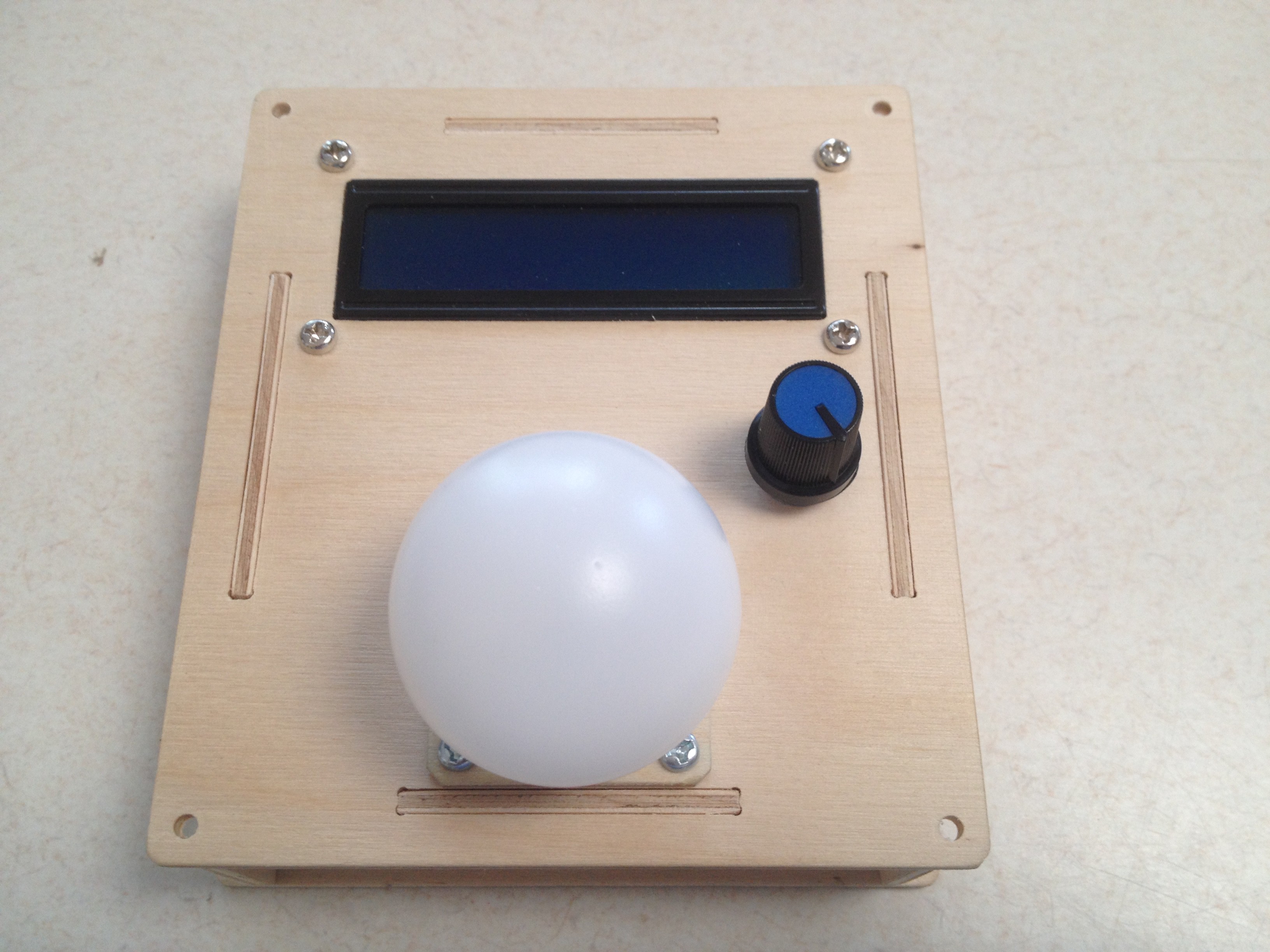
02/04/2018 at 11:37 • 0 commentsThe Box
Need a box to put the electronics in. I have a DeltaCAD macro that generates boxes for a laser cutter. For this project I modified the macro for a router type CNC machine. Makes sense as I don't have a laser cutter but I do have a router CNC machine.
The Macro (CaseII.bas)
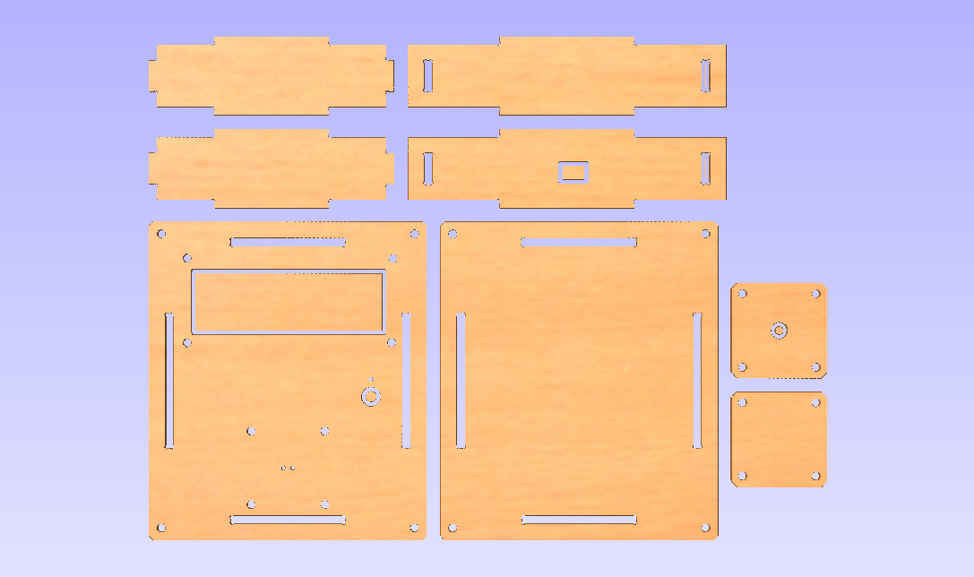
The macro is not very clever. It is just a long list of line commands with each point carefully calculated and checked. After editing the initial box generated by the macro this is what it looks like:
![]()
I used a new bit this time but it was smaller than the 1.5 mm diameter that I assumed. I had to sand back all the mating surfaces for the box to fit.
DeltaCAD is a great interactive CAD package. The macro language is okay (a type VB Script), the editor is pretty poor though. It runs well under WINE but not the macro laguage. So I have a spare Windows PC just for this job! I may have to find a DXF library and use C to write my CAD macro in future.
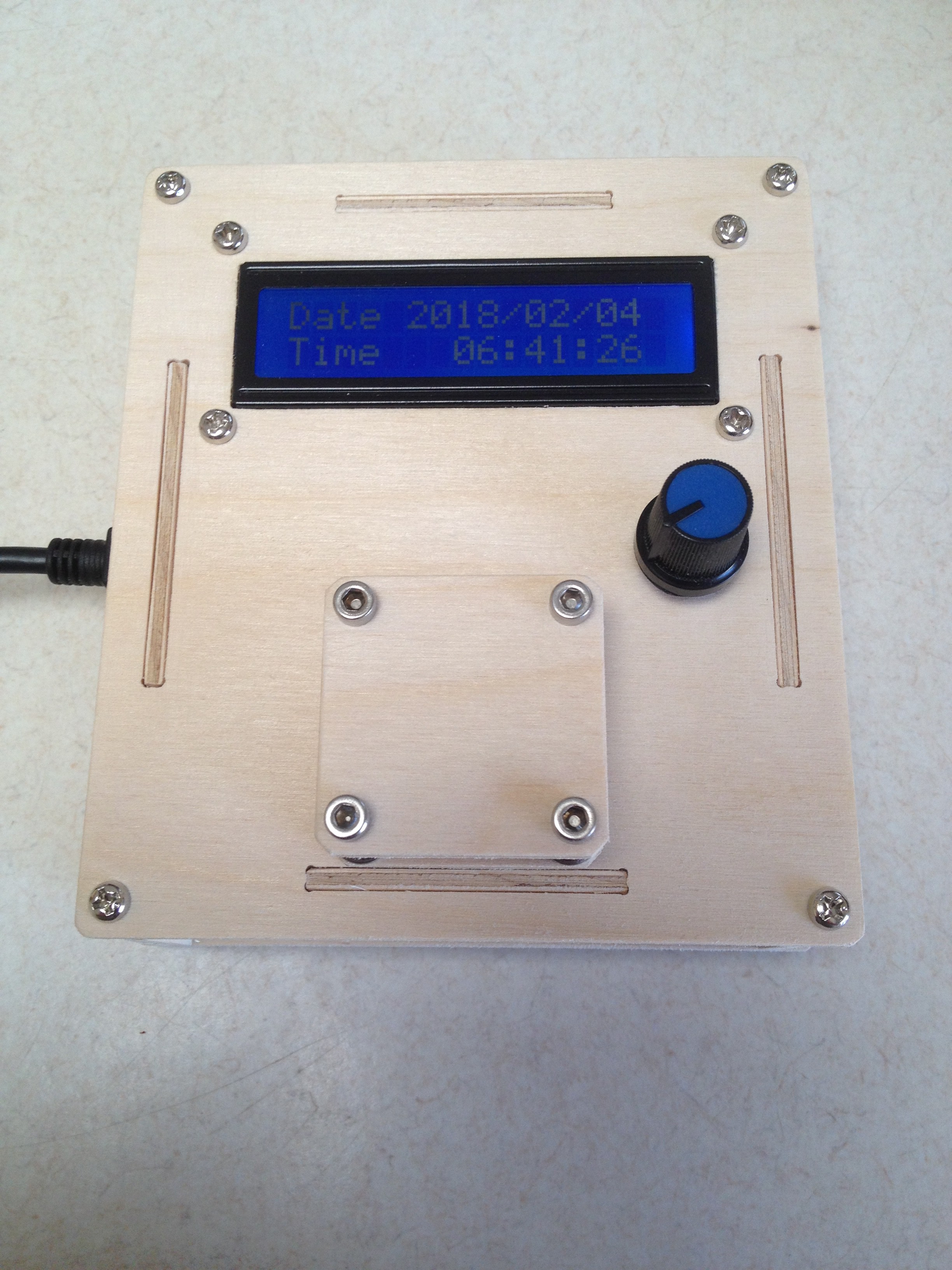
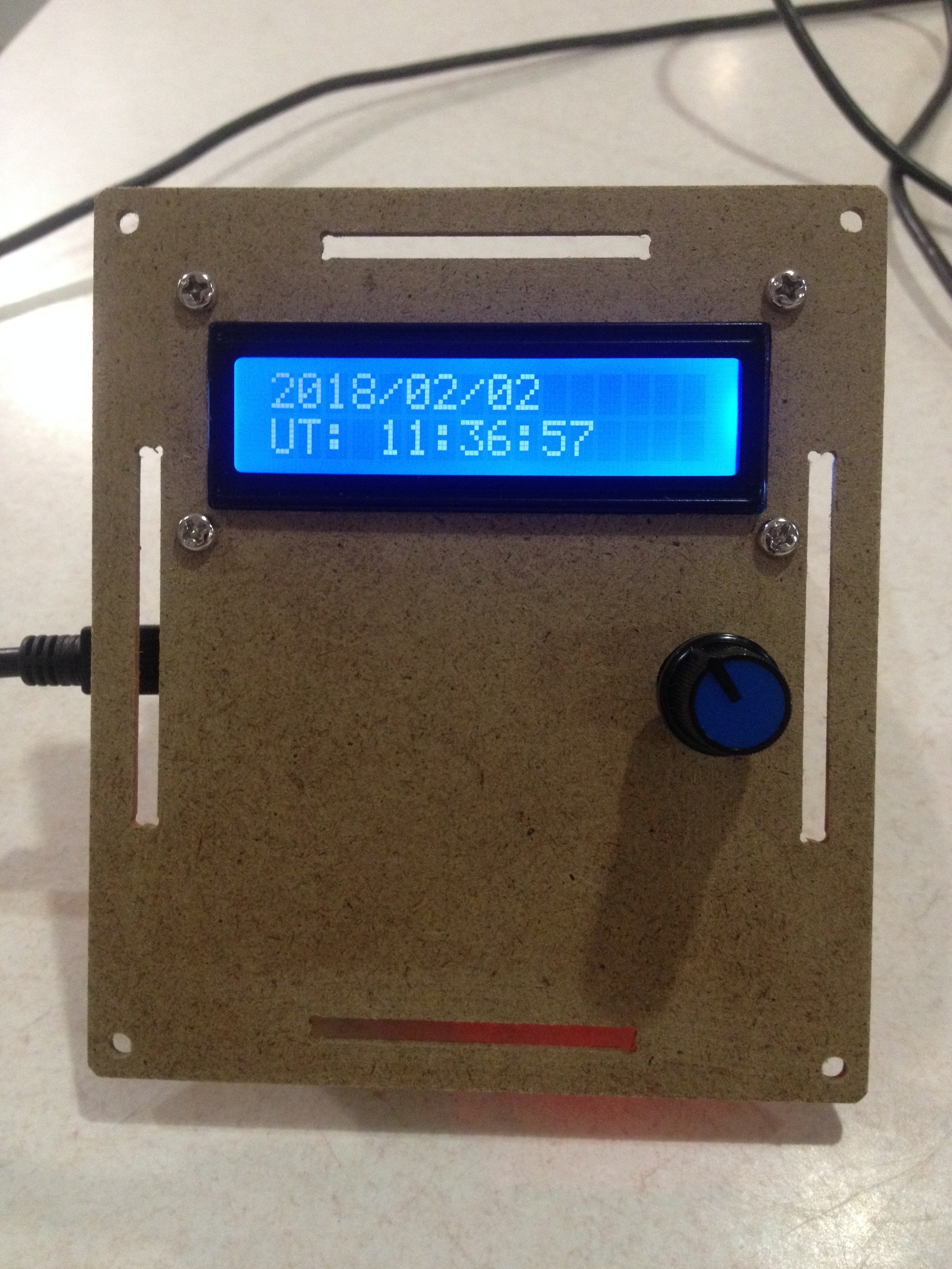
Here is the box assembled:
![]()
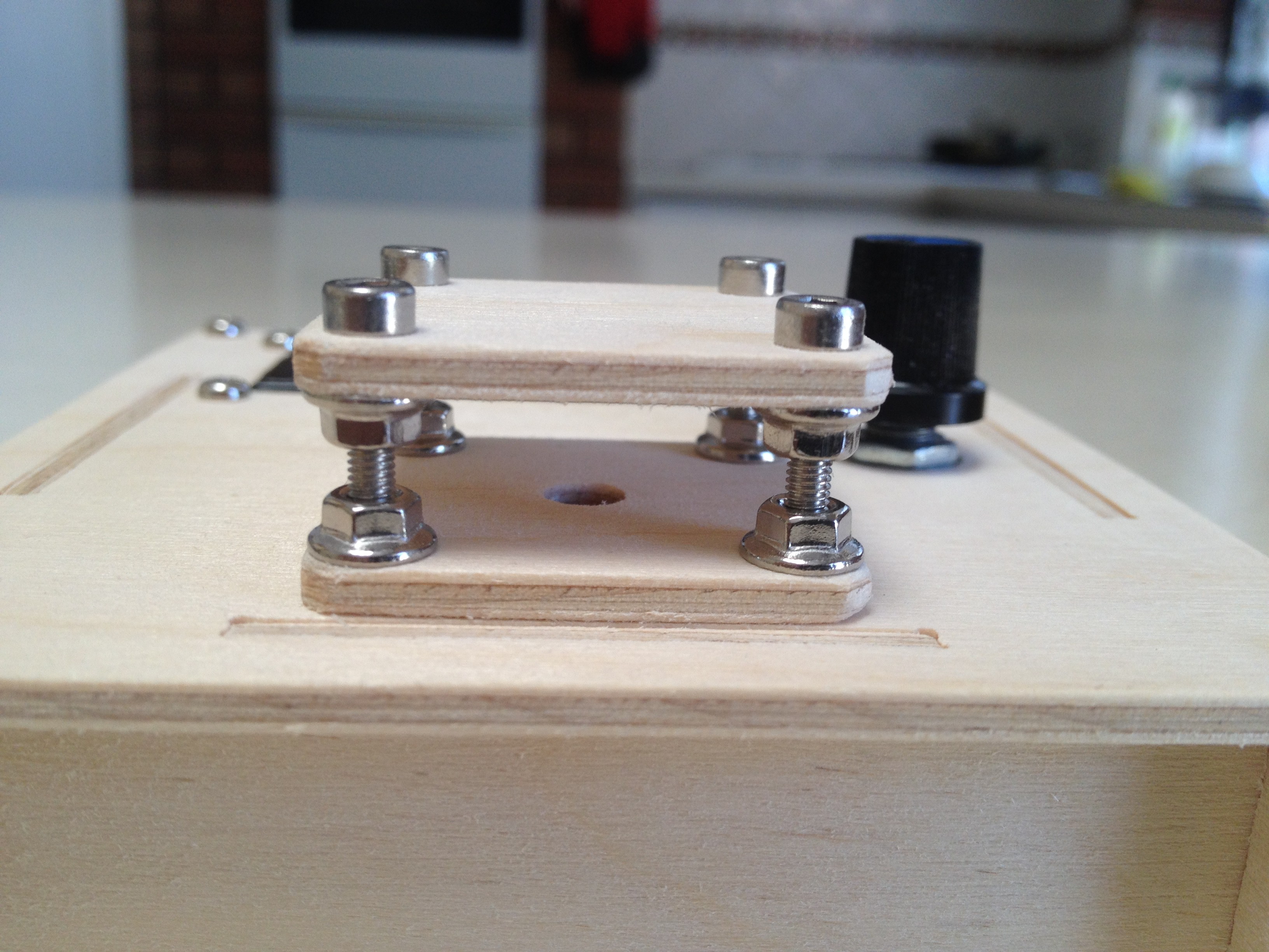
So it has an LCD, a rotary encoder/pushbutton switch, a micro-USB input and a umbrella for the LDR light sensor. Here is a view under the umbrella:
![]()
The idea of the umbrella it to keep direct light off the LDR. The umbrella probably should be a bit lower or have an extra light gard ring around it.
I prototyped the top of the box before making the full box. Here is the prototype:
![]()
At this pont of time I had not worked out where to put the light sensor.
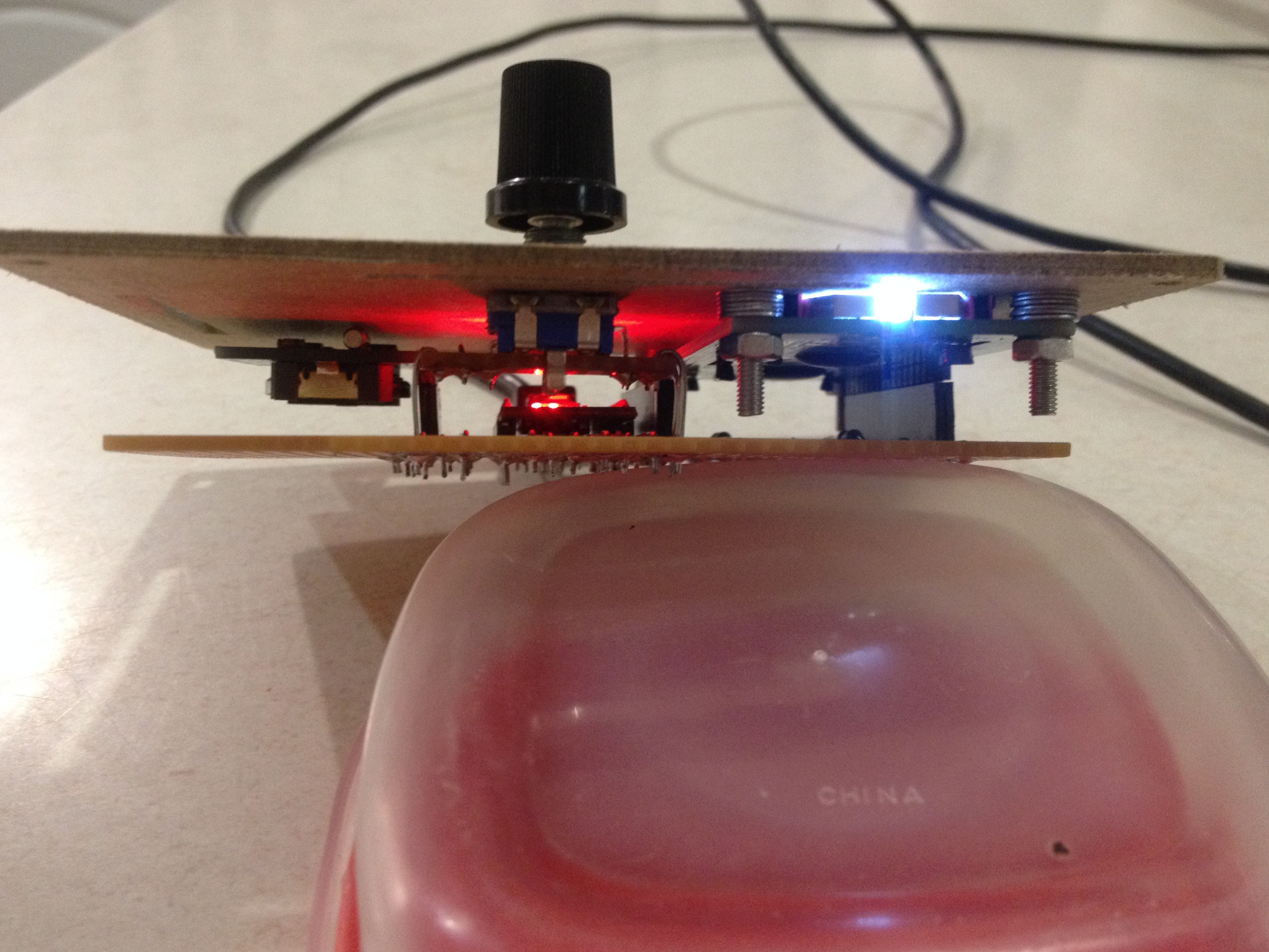
This is what the electronics looks like from the side:
![]()
Magic
-
The Mathematics
02/04/2018 at 09:04 • 0 commentsJulian Day (JD) number
Most astronomy based formulas use the Julian day number as an input.
I use the a modified 2000 Julian Day number, the number of days since mid-night of the 1st of January 2000:
double J2000(long Year,long Month,long Day,double UT) {
  double JD;

  // Julian (2000) Day Number
  JD=(367*Year-(7*(Year+(Month+9)/12))/4+275*Month/9+Day);
  JD=JD-730531.5;
  JD=JD+UT/24.0;

  return JD;
}
The formular is correct even for dated before 1/1/2000.
One of the inputs to the function is UT or Universal Time. UT is the time in Greenwich UK. I will write more about this later.
Note that Year, Month and Day are type long. Therefore integer division rules apply.
Reverse of the Julian Day number
I found a source for calculating the reverse of the 2000 Julian Day Number:
Source: http://mathforum.org/library/drmath/view/51907.htm
  unsigned long JD,p,q,r,s,t,u,v;

  p=JD+2451545+68569;
  q=4*p/146097;
  r=p-(146097*q+3)/4;
  s=4000*(r+1)/1461001;
  t=r-1461*s/4+31;
  u=80*t/2447;
  v=u/11;
  Year=100*(q-49)+s+v;
  Month=u+2-12*v;
  Day=t-2447*u/80;
It may be useful when checking/calculating valid dates. I checked the code and it good from 1/1/2000 to 31/12/2099 but then the Julian Day number calculation is only good to 31/12/2099.
Greenwich Mean Sideral Time (GMST)
This is the time of the stars! You would be aware that there are 365.25 days in a solar year. But the stars rotate around the earth 366.25 times a year. The extra rotation is because the earth also rotates around the sun as well as rotating around it axis. Here is the GMST function:
double GMST(double JD,double UT) {
  double gmst;

  // Greenwich Mean Sidereal Time (~36625/36525)
  gmst=18.697374558+24.06570982441908*(JD+UT/24.0);
  gmst=fmod(fmod(gmst,24.0)+24.0,24.0);

  return gmst;
}
We need GMST even for the sun as the sun is cosidered just another start. But the Right Ascension and Declination moves a lot more than ordinary stars.
Sun Right Ascension (RA) and Declination (Dec)
Now we can calculate the position of the sun amongst the stars. I use a series of formulas from my copy of the "The Astronomical Amanac (1986)" but I have seen the same formulas on the Internet:
void SunData(double JD,double *RA,double *Dec,double *EoT) {
  double L,g,a,b,c;

  /* Source: Page C24 from "The Astronomical Almanac" (1986) */
  // Mean longitude of Sun, corrected for aberration
  L=280.460+0.9856474*JD;
  L=fmod(fmod(L,360.0)+360.0,360.0);
  // Mean anomaly
  g=357.528+0.9856003*JD;
  g=fmod(fmod(g,360.0)+360.0,360.0);
  // Ecliptic longitude
  a=L+1.915*sin(g*M_PI/180)+0.020*sin(2*g*M_PI/180);
  a=fmod(fmod(a,360.0)+360.0,360.0);
  // Ecliptic latitude
  b=0;
  // Obliquity of ecliptic
  c=23.439-0.0000004*JD;
  c=fmod(fmod(c,360.0)+360.0,360.0);
  // Right ascension
  (*RA)=atan2(cos(c*M_PI/180)*sin(a*M_PI/180),cos(a*M_PI/180))*12/M_PI;
  if ((*RA)<0) (*RA)=(*RA)+24.0;
  // Equation of Time
  (*EoT)=(L/15.0-(*RA));
  // Declination
  (*Dec)=asin(sin(c*M_PI/180)*sin(a*M_PI/180))*180/M_PI;
}
The procedure accepts modified Julian Day number (JD) and returns Right Ascension (RA), Declination (Dec) and the Equarion of Time (EoT). The units for RA and EoT are hours but the units for Declination is degrees.
Checking the formulas
It is really easy to make a minor mistake with these formulas so it is important to check the results against a worked example. The Internet has many calculators that you can check your results against.
Sunrise and sunset
Sunrise and sunset times are published on the Internet for any place that you live.
On the 20th of January 2018 in Perth Western Australia the Sunrise was 5:30 and Sunset was 19:24. Local noon was therefore 12:27. The local time is 8 hours ahead of UT.
Calculating longitude
The steps are:
- SunRise=5.50-8;
- SunSet=19.40-8;
- JD=J2000(Year,Month,Day,(SunRise+SunSet)/2.0);
- SunData(JD,&RA,&Dec,&EoT);
- Lon=15.0*(RA-GMST(JD,0.0));
The values were:
- Year 2018
- Month 1
- Day 20
- SunRise (LT) 5.5000
- SunSet (LT) 19.400
- SunRise (UT) -2.5000
- SunSet (UT) 11.4000
- JD 6593.68554687
- RA 20.14925956
- Dec -20.13604354
- EoT -0.18200683
- Longitude 115.9108
Which are correct.
Calculating latitude
Originally I used an iterative method but Jaromir Sukuba work out an exact answer:
double latitude(double SunRise,double SunSet,double Alt,double Dec) {
  // The mathematics:
  //   Cos(15*DL/2)=Sin(Alt)/Cos(Dec)/Cos(Lat)-Tan(Dec)*Tan(Lat)
  //   Use this model:
  //     C=B*Cos(Lat)+A*Sin(Lat)
  //     D=Sqrt(A*A+B*B);
  //     Sin(U)=B/D;
  //     Sin(V)=C/D;
  //     U=ASIN(B/D);
  //     V=ASIN(C/D);
  //     Lat=V-U;
  //  Rearrange:
  //     Sin(Alt)/Cos(Dec)=Cos(15*DL/2)*Cos(Lat)+Tan(Dec)*Sin(Lat))
  //  Test data:
  //     SunRise       5.50 (need not be local time)
  //     SunSet       19.40 (need not be local time)
  //     DayLight     13.90
  //     Altitude     -0.833 (definition for Sun rise/set)
  //     Declination -20.066095
  //     Latitude    -31.9615789037
  double DL,A,B,C,D,U,V,Lat;

  if (fabs(Dec-Lat)>90.0) return -90.0; // Check if sun rises
  if (fabs(Dec+Lat)>90.0) return +90.0; // Check if sun sets
  DL=SunSet-SunRise;                    //  13.90
  A=tan(Dec*PI/180);                    //  -0.3652771781
  B=cos(DL*PI/24);                      //  -0.246153293
  C=sin(Alt*PI/180)/cos(Dec*PI/180);    //  -0.015477611
  D=sqrt(A*A+B*B);                      //   0.4404757207
  if (fabs(C)<=D) {                     // Check if out of range
    U=asin(B/D)*180/PI;                 // -33.9752753119
    V=asin(C/D)*180/PI;                 //  -2.0136964081
    Lat=V-U;                            // -31.9615789037
    if (Dec<0) Lat=-Lat;                // -31.9615789037
  } else {
    Lat=-90;
  }
  return Lat;
}
If we apply our numbers to this function then the answer is:
6. Lat=latitude(SunRise,SunSet,Alt,Dec);
- Latitude -31.8655
Which is correct.
The only variable not discussed here is Alititude (Alt). Altitude is the angle from the horizon. For sunrise and sunset the offical altitude (nainlt due to reflaction) is -0.833 degrees (i.e. below the horizon), not 0 degrees.
Some code to try
Here is some arduino code:
double J2000(long Year,long Month,long Day,double UT) {
  double JD;

  // Julian (2000) Day Number
  JD=(367*Year-(7*(Year+(Month+9)/12))/4+275*Month/9+Day);
  JD=JD-730531.5;
  JD=JD+UT/24.0;

  return JD;
}

double GMST(double JD,double UT) {
  double gmst;

  // Greenwich Mean Sidereal Time (~36625/36525)
  gmst=18.697374558+24.06570982441908*(JD+UT/24.0);
  gmst=fmod(fmod(gmst,24.0)+24.0,24.0);

  return gmst;
}

void SunData(double JD,double *RA,double *Dec,double *EoT) {
  double L,g,a,b,c;

  /* Source: Page C24 from "The Astronomical Almanac" (1986) */
  // Mean longitude of Sun, corrected for aberration
  L=280.460+0.9856474*JD;
  L=fmod(fmod(L,360.0)+360.0,360.0);
  // Mean anomaly
  g=357.528+0.9856003*JD;
  g=fmod(fmod(g,360.0)+360.0,360.0);
  // Ecliptic longitude
  a=L+1.915*sin(g*M_PI/180)+0.020*sin(2*g*M_PI/180);
  a=fmod(fmod(a,360.0)+360.0,360.0);
  // Ecliptic latitude
  b=0;
  // Obliquity of ecliptic
  c=23.439-0.0000004*JD;
  c=fmod(fmod(c,360.0)+360.0,360.0);
  // Right ascension
  (*RA)=atan2(cos(c*M_PI/180)*sin(a*M_PI/180),cos(a*M_PI/180))*12/M_PI;
  if ((*RA)<0) (*RA)=(*RA)+24.0;
  // Equation of Time
  (*EoT)=(L/15.0-(*RA));
  // Declination
  (*Dec)=asin(sin(c*M_PI/180)*sin(a*M_PI/180))*180/M_PI;
}

double latitude(double SunRise,double SunSet,double Alt,double Dec) {
  // The mathematics:
  //   Cos(15*DL/2)=Sin(Alt)/Cos(Dec)/Cos(Lat)-Tan(Dec)*Tan(Lat)
  //   Use this model:
  //     C=B*Cos(Lat)+A*Sin(Lat)
  //     D=Sqrt(A*A+B*B);
  //     Sin(U)=B/D;
  //     Sin(V)=C/D;
  //     U=ASIN(B/D);
  //     V=ASIN(C/D);
  //     Lat=V-U;
  //  Rearrange:
  //     Sin(Alt)/Cos(Dec)=Cos(15*DL/2)*Cos(Lat)+Tan(Dec)*Sin(Lat))
  //  Test data:
  //     SunRise       5.50 (need not be local time)
  //     SunSet       19.40 (need not be local time)
  //     DayLight     13.90
  //     Altitude     -0.833 (definition for Sun rise/set)
  //     Declination -20.066095
  //     Latitude    -31.9615789037
  double DL,A,B,C,D,U,V,Lat;

  DL=SunSet-SunRise;                    //  13.90
  A=tan(Dec*PI/180);                    //  -0.3652771781
  B=cos(DL*PI/24);                      //  -0.246153293
  C=sin(Alt*PI/180)/cos(Dec*PI/180);    //  -0.015477611
  D=sqrt(A*A+B*B);                      //   0.4404757207
  if (fabs(C)<=D) {                     // Check if out of range
    U=asin(B/D)*180/PI;                 // -33.9752753119
    V=asin(C/D)*180/PI;                 //  -2.0136964081
    Lat=V-U;                            // -31.9615789037
    if (Dec<0) Lat=-Lat;                // -31.9615789037
  } else {
    Lat=0.0;
  }
  return Lat;
}

void setup()  {
  Serial.begin(9600);
  while (!Serial);

  // Day Light to Lat/Long
  int Year,Month,Day;
  double LTC,UT,JD,SunRise,SunSet,RA,Dec,EoT,Lat,Lon,Alt;

  LTC=8.0;  // Local Time Correction
  Year=2018;
  Month=1;
  Day=20;
  Alt=-0.833;                // Sunrise and Sunset definition
  SunRise=5.0+30.0/60.0-LTC; // Convert Local Time to Universal Time
  SunSet=19.0+24.0/60.0-LTC; // Convert Local Time to Universal Time

  // Problem parameters:
  Serial.println("DayLight to Latitude:");
  Serial.print("Year        ");Serial.println(Year);
  Serial.print("Month       ");Serial.println(Month);
  Serial.print("Day         ");Serial.println(Day);
  Serial.print("SunRise(UT) ");Serial.println(SunRise,4);
  Serial.print("SunSet (UT) ");Serial.println(SunSet,4);

  // Solve the problem:
  JD=J2000(Year,Month,Day,(SunRise+SunSet)/2.0);
  SunData(JD,&RA,&Dec,&EoT);
  Lat=latitude(SunRise,SunSet,Alt,Dec);
  Lon=15.0*(RA-GMST(JD,0.0));

  // Debug:
  Serial.print("JD          ");Serial.println(JD,8);
  Serial.print("RA          ");Serial.println(RA,8);
  Serial.print("Dec         ");Serial.println(Dec,8);
  Serial.print("EoT         ");Serial.println(EoT,8);

  // Solution:
  Serial.print("Latitude    ");Serial.println(Lat,4);
  Serial.print("Longitude   ");Serial.println(Lon,4);
  Serial.println();
}

void loop(){

}
And here is the run:
DayLight to Latitude:
Year        2018
Month       1
Day         20
SunRise(UT) -2.5000
SunSet (UT) 11.4000
JD          6593.68554687
RA          20.14925956
Dec         -20.13604354
EoT         -0.18200683
Latitude    -31.8655
Longitude   115.9108
Conclusion
For many places in the world if you can measure sunrse and sunset accuarately you can calculate your latitude and longitude accurately. There are places/dates where the sun does not set or rise, in these places/dates the mathematics does not work.
Magic
Daylight Geolocator Remix
This is a remix of https://hackaday.io/project/28550-light-level-geolocator