 lion mclionhead
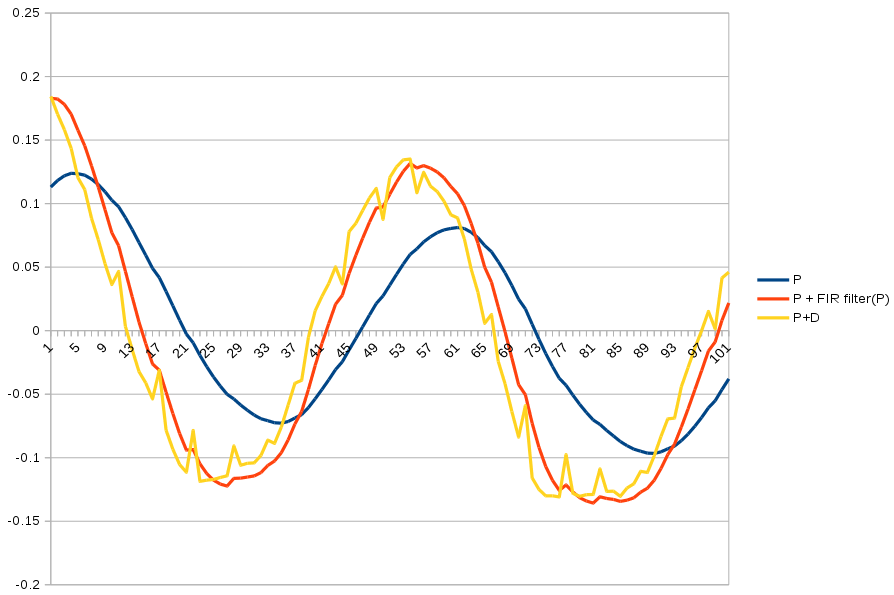
A student lion could derive FIR filters directly from laplace notation of AC circuits. Nowadays, all lions can do is look it up on kiwipedia. Using actual driving data recorded on the Odroid, the highpass filter was a more delayed & smoother version of the D feedback. The highpass filter needs the D scaler & a bandwidth from 0-1.
The highpass filter is:
y = bandwidth * (prev_y + input[i] - input[i - 1])
prev_y = y
The D in the original PD feedback fights all the frequencies of the input.
output = P * input[i] + D * (input[i] - input[i - 1])
If the (input[i] - input[i - 1]) is replaced by the highpass filter, the D now fights only high frequencies of the input.
output = P * input[i] + D * y
You get a sharper cutoff by stacking multiple highpass filters.
y = bandwidth * (prev_y + input[i] - input[i - 1])
y2 = bandwidth * (prev_y2 + y - prev_y)
prev_y = y
prev_y2 = y2
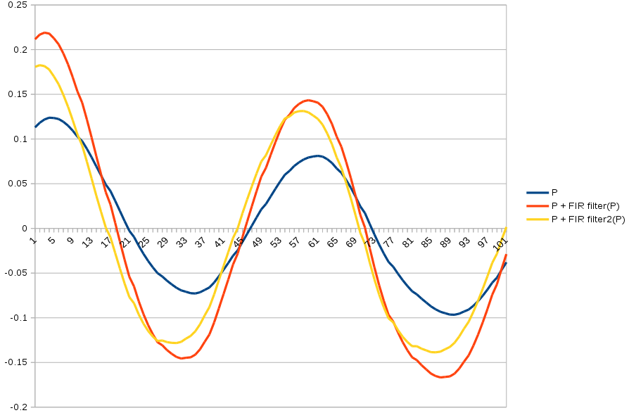
FIR filter2 varies much more greatly by bandwidth & gets farther ahead than the single order filter.
Kiwipedia has a complicated formula for calculating bandwidth, so lions just graph it until it looks good. It has to be 0.9 to 1.
Discussions
Become a Hackaday.io Member
Create an account to leave a comment. Already have an account? Log In.