 lion mclionhead
For determining gain & bandwidth constants, there's the bode plot.
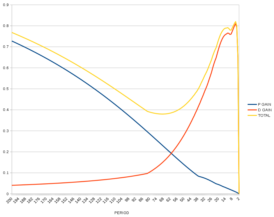
If the traditional damping method involves a highpass filter, a notch filter at the resonant frequency should be even better.
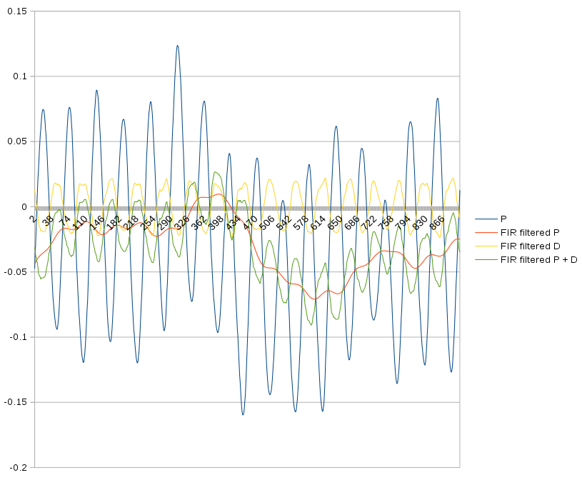
When applied to the test data, it nicely leads in the high frequencies but lags in the low frequencies.
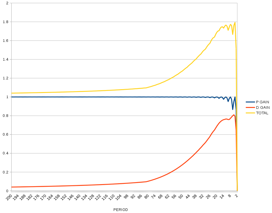
So back to just high passing.
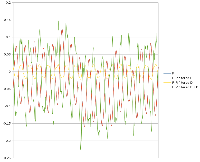
Test data shows some ability to vary the amount of leading by varying the D gain & filter stages.
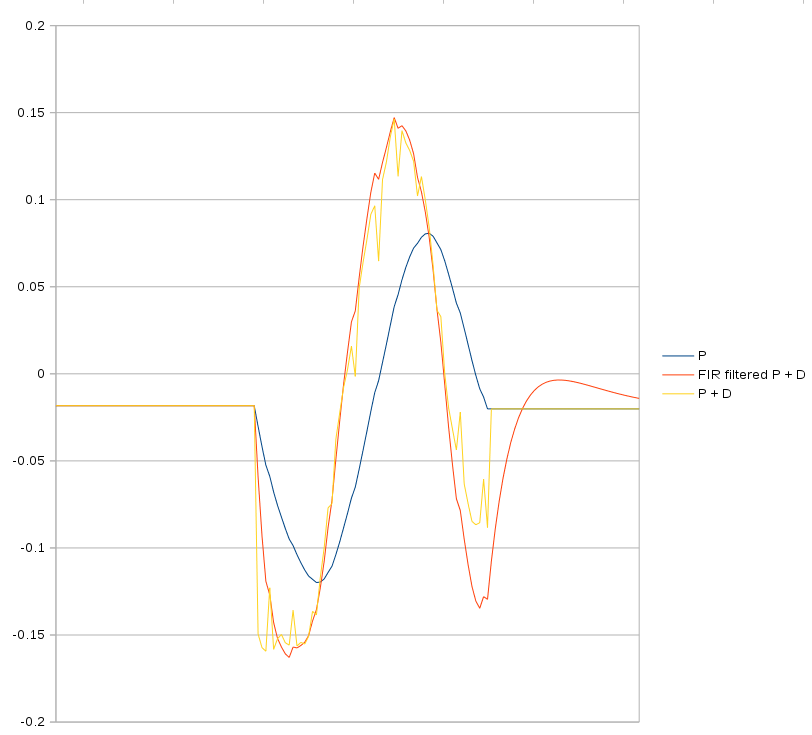
A single wavelength gives some idea of what's leading. The more filter stages, the more the highpass leads the input, but it doesn't do anything dramatically different than the unfiltered feedback.
Discussions
Become a Hackaday.io Member
Create an account to leave a comment. Already have an account? Log In.