Close
0%
0%

Bringing Cool Relief to Multiple Sclerosis

Cooling the core body temperature of people diagnosed with MS.

Similar projects worth following
Did you know that 60 to 80 % of people diagnosed with Multiple Sclerosis show extreme sensitivity to heat? When the core body temperature increases, some of the most common MS symptoms worsen, including fatigue, limb weakness, visual problems, pain and numbness and cognitive dysfunctions. Devices to cool the core body temperature of those suffering from MS are few. They include a cooling vest that requires the wearer to insert cold packs into vest pockets and only last a few hours. Other devices are everyday fans or people sitting in air-conditioned vehicles or rooms.
My device is a wearable shirt that circulates cooling gel through silicone tubing. By using mini Refrigeration the shirt will provide cooling for up to eight hours. The hardware will be enclosed in a small backpack. The shirt is actively controlled by an embedded system that monitors body temperature and cooling liquid temperature. This will allow the wearer to maintain a normal body temperature in hot environments.

This project has six systems that make up the cooling pack system.

  1. Power Management:
    1. Charger/Li-ion cell balancer.
    2. Dual battery pack management.(implemented in later models)
    3. Li-ion charger and DC/solar power input.
    4. TI MSP430 microcontroller power control brain.
  2. Thermal Management:
    1. Heat Exchanger temperature monitoring.
    2. Mini Compressor running temperature.
    3. Coolant tubing temperature monitoring.
    4. User body temperature monitoring.
    5. Ambient temperature monitoring.
  3. Pump, Compressor, Valve, and Fan Management:
    1. Refrigeration compressor BLDC driver.
    2. Coolant pump driver.
    3. Servo valve controller.
    4. Cooling fan driver.
  4. Display and User Input:
    1. TI CC3100 WIFI Radio to connect to Andriod or iOS devices
  5. Mechanics:
    1. Backpack.
    2. Shirt tubing.
    3. Electronics system PCB/wiring.
    4. Cooling chamber and plumbing.
    5. Insulation.
  6. Brain/Main Control:
    1. Microcontroller MSP430.

The way the cooling system works is as follows:

The system has three main parts: The power system which supplies 24 volts to the compressor and 12V, 3.3V, 5V volts to the fans, microcontrollers, and servo valves. The mini refrigeration system which uses R134A refrigerant to cool the liquid coolant. Lastly, the liquid coolant circulation and control system. This system circulates the coolant through the shirt, controls the servo valves, and monitors the temperatures.
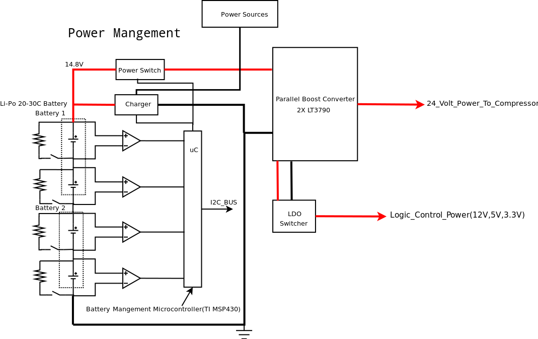
Battery Power System

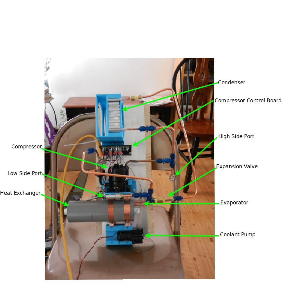
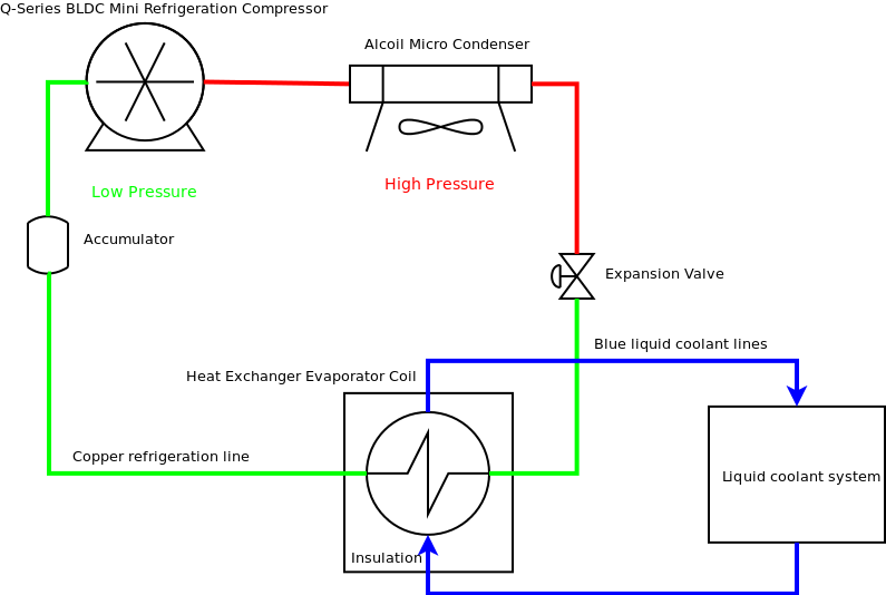
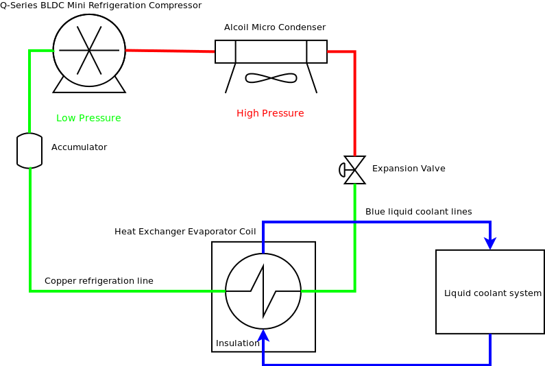
This is the refrigeration system block diagram shown below which has four main parts: the compressor, Condenser, Expansion valve, heat exchanger evaporator coil, and Accumulator. I am not going to discuss how a refrigeration system works in this project, since it is something easily researchable. This systems job is to cool the liquid coolant flowing into the heat exchanger to the desired cold temperature. The heart of the system is the Aspen Q-series low noise, miniature, rotarty BLDC compressor. This compressor runs of 24V, has a 360W cooling capacity, 40dBA noise level, and weighs 900g.
Aspen Compressor datasheet

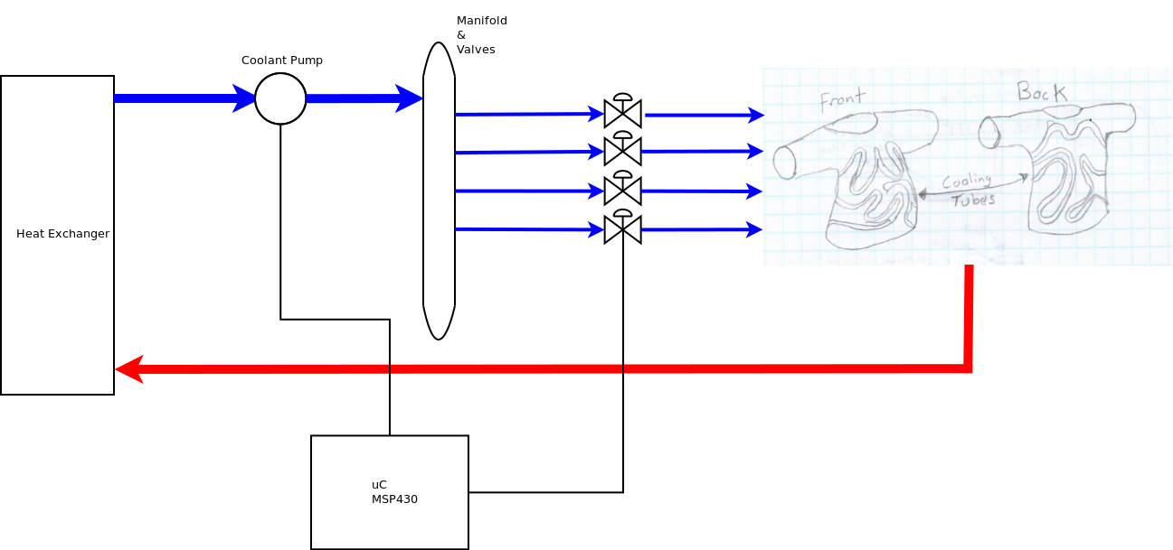
The cooling liquid, which will be an ethylene glycol and water mixture, will be pumped through 1/4" tubing. This tubing will be attached to a shirt that will fit snugly to the body. This cooling liquid will be cooled in a heat exchanger that houses the refrigeration evaporator copper coil. The heat exchanger chamber will allow the liquid coolant to flow around the evaporator coil allowing it to cool the liquid that is being pumped into the chamber. Then the coolant will be pump out via the servo valves to each cooling tube circuit. The pump and valves there then turn off to save power. At this point the cooling tubing circuits temperatures are monitored by the main microcontroller. As the coolant heats up, it passes a programmed threshold. The microcontroller will activate the pump and valves to pump the warm coolant out and new cool coolant into the tubes. This duty cycle-based system will save power and is projected to run 8 hours.

This project is being fully funded and endorsed by the National MS Society through the MS Entrepreneurs Grant. In June of this year, II was selected to receive the MS entrepreneurs grant to build this project.

View all 21 components

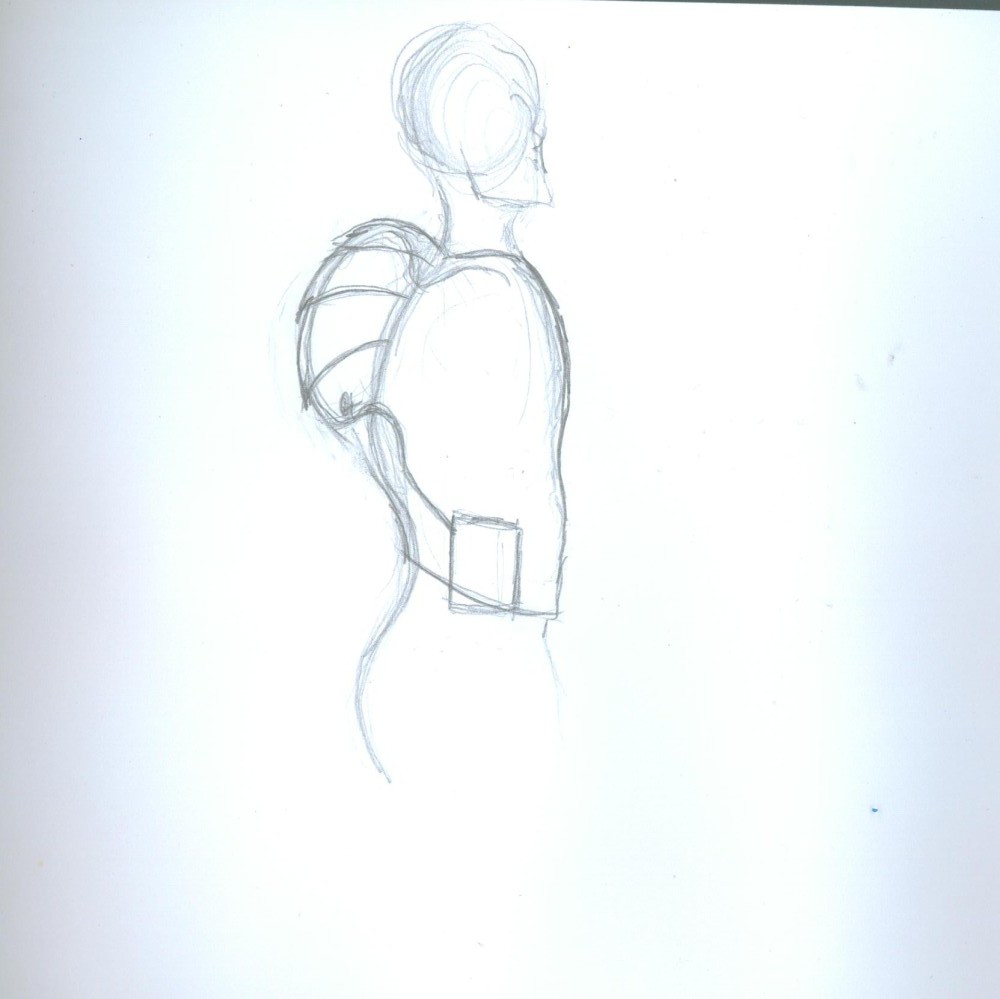
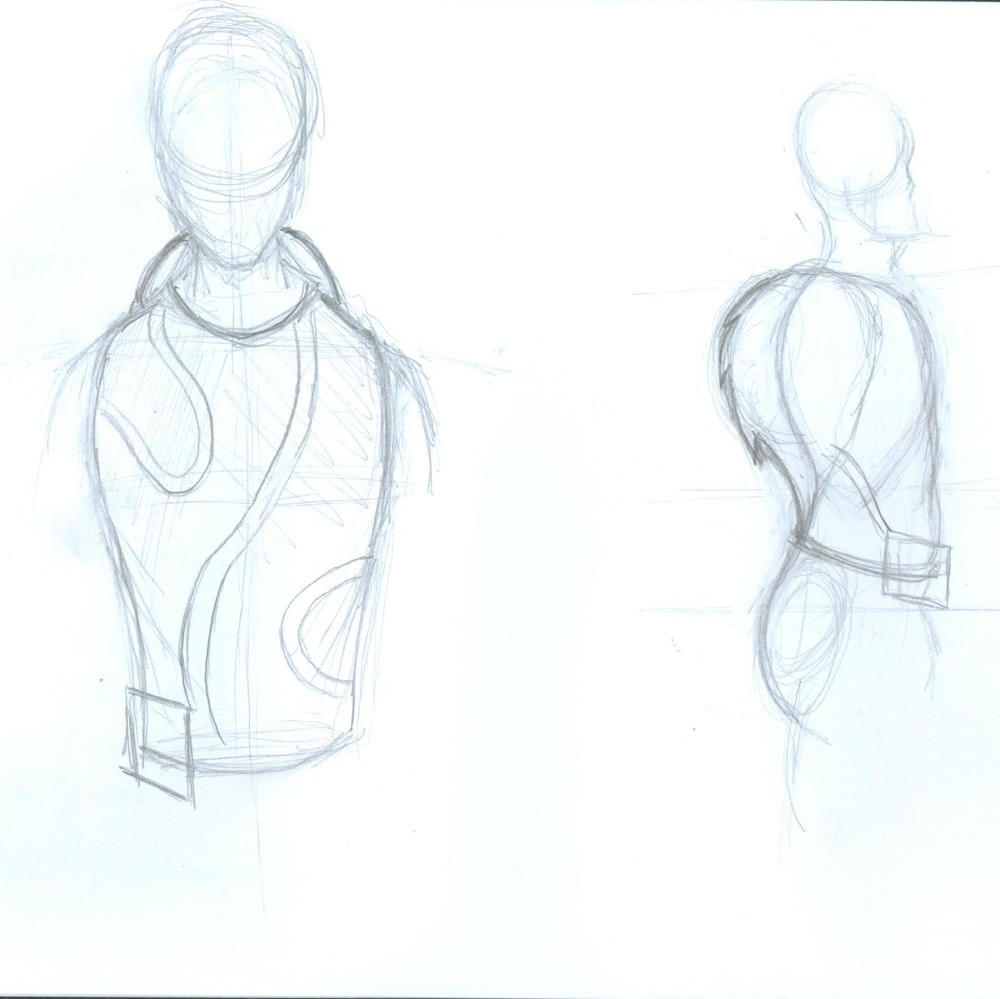
  • Artist’s Renditions

    extremerockets09/21/2015 at 19:22 0 comments

    Showing coolant tubing.

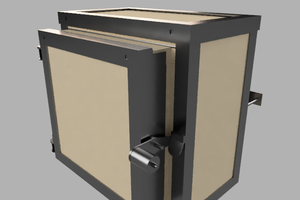
    Cooling backpack optimal design look with servo valve hip belt.

    Front and side views.

  • Testing the Mini Refrigeration System

    extremerockets09/21/2015 at 01:02 0 comments

    Here is a video of my compressor testing. One thing that I am not sure about is how much R134A refrigerant I should charge the system with. I am also not completely sure what the high or low side pressures should be normally. I know that the high side pressure should not go above 350 psi. Overall the cool liquid does get rather cold. I need to get a better thermocouple because I believe mine is not very accurate.

  • Building the Mini Refrigeration System

    extremerockets09/20/2015 at 23:09 0 comments

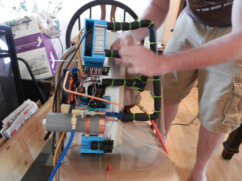
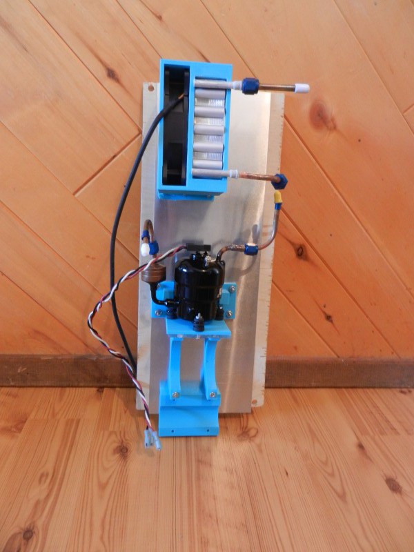
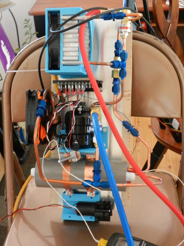
    This part of the project turned out to be quite a challenge! In my past project logs I have said that I am going to be using refrigeration to cool the liquid flowing through the shirt. The refrigeration system has only four main parts: the compressor and control board, condenser, evaporator, and expansion valve. The picture below is the version that worked. My first attempt failed to hold a vacuum and was very leaky. I will show the failed system later in the log.

    Above: Working second version of the refrigeration system.

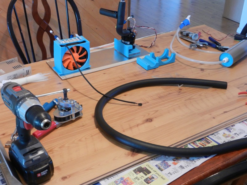
    I used my 3D printer to make the mounting parts for the compressor, condenser and fan, and the heat exchanger and coolant pump.

    Above: Shows my 3D printed mounting hardware bolted onto the start of my prototype backpack frame.

    Here pictured above is my first failed attempt. I used AN fittings with flared copper tubing. I learned two things from this first attempt. First, I learned that you can over tighten AN fittings. Second, my problem was that I did not correctly make the 37 degree flares for the AN fittings. My flares were too small and did not correctly mate up with the aluminum AN fitting. As a result the whole system leaked like crazy.

    Above is the second attempt at connecting the system. I made the copper tubing flares much bigger so that the copper tube and the AN fittings mated up correctly. I also minimized the amount of connections as much as possible. Then I moved the expansion port to be right in front of the evaporator coil. I was able to get my vacuum pump to pull a vacuum on my system. Now, off to charge the system with R134A and see if the heat exchanger gets cold.

    A quick note on the compressor control board. The board came with the compressor when I ordered it from Aspen Compressor. I don't have any schematics on it since it's proprietary to Aspen. I plan on building my own driver board later on down the road, but for now I am using Aspen's control board for testing and prototyping purposes.

  • Proof of Concept Cooling Shirt

    extremerockets09/20/2015 at 02:17 0 comments

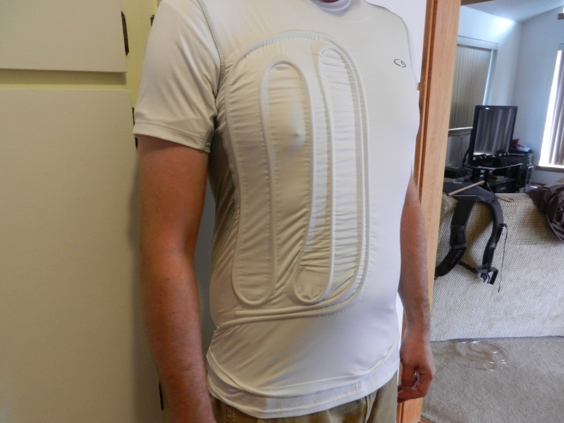
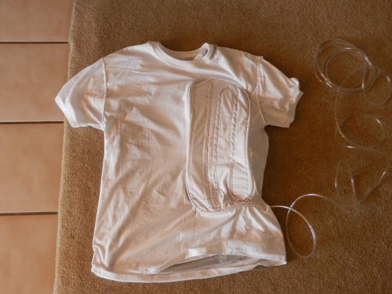
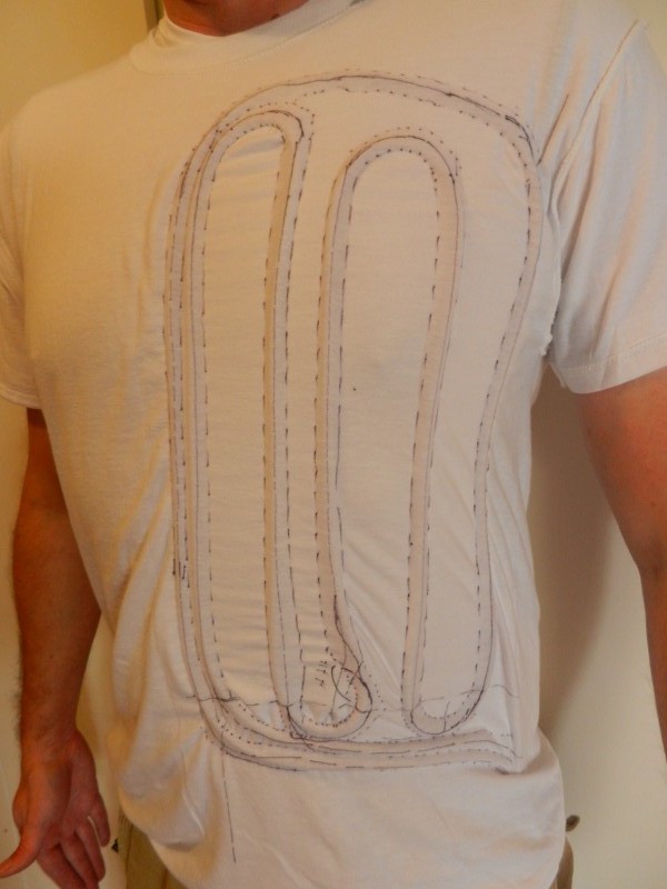
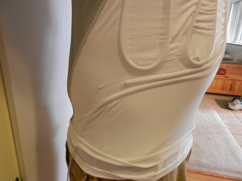
    This post is on the actual shirt containing the cooling tubing. In this step, I wanted to see if the cooling shirt worked the way I expected it to. This is why I only have one cooling loop sewn into the shirt. I constructed the cooling shirt by using a fitted outside shirt. You can see below that I purchased a Champion brand Duodry shirt. Underneath, I have a regular white cotton Haynes shirt. The purpose of the fitted shirt is to pull the cooling tubing close to the body making sure that there is good thermal contact. The cotton shirt is just to provide a way to make a channel for the cooling tubing. The tubing I used was 1/4" OD .170" ID vinyl tubing.

    Above: One cooling loop finished for the proof of concept.

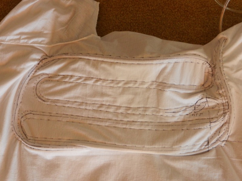
    The photo below shows a close up of the inside of the cooling shirt. The tubing channels were made by sewing the cotton shirt to the inside of the fitted shirt. This created fabric channels for tubing to run through. The cotton shirt can be trimmed away leaving only the cotton channels behind. I have not trimmed the cotton shirt yet because I plan on sewing three more cooling channels into the shirt.

    Above: Cooling shirt channel pattern.

    Cooling tubing threaded into the fabric channels.

    Close up of the cooling shirt inside out showing the channel pattern and tubing.

    Close up showing the shirt right side out with the tubing entrance and exit channels.

  • Heat Exchanger

    extremerockets09/15/2015 at 23:03 0 comments

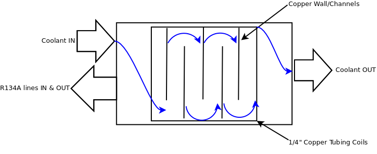
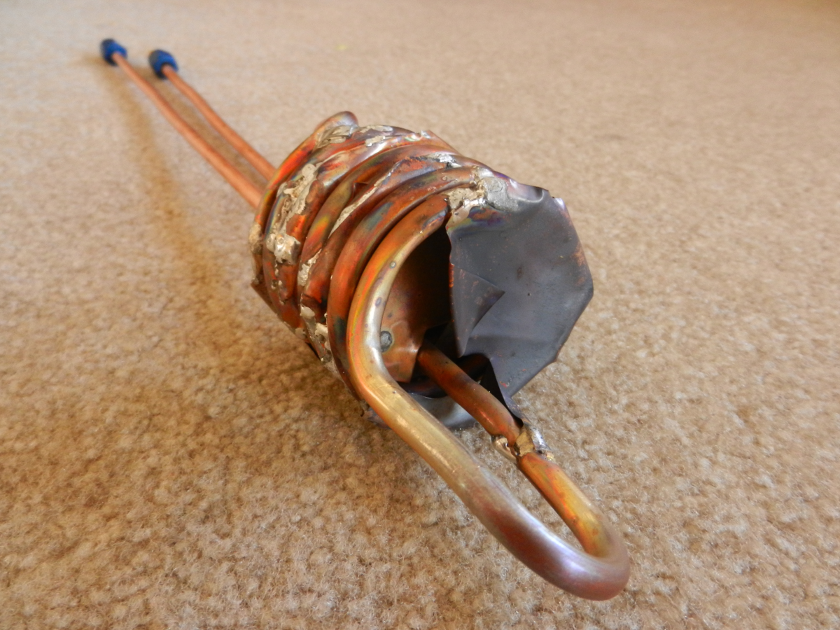
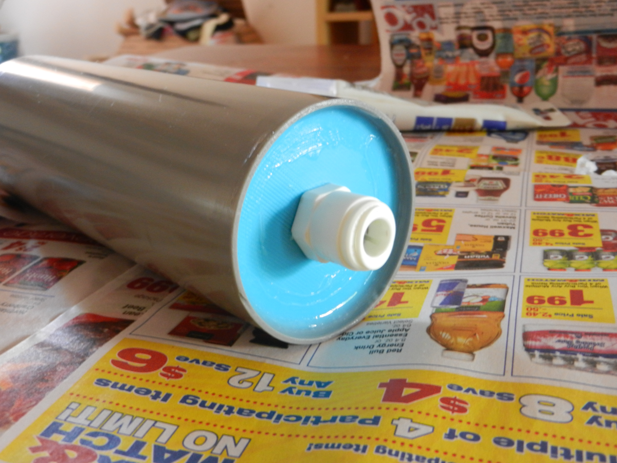
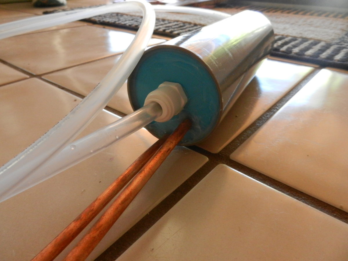
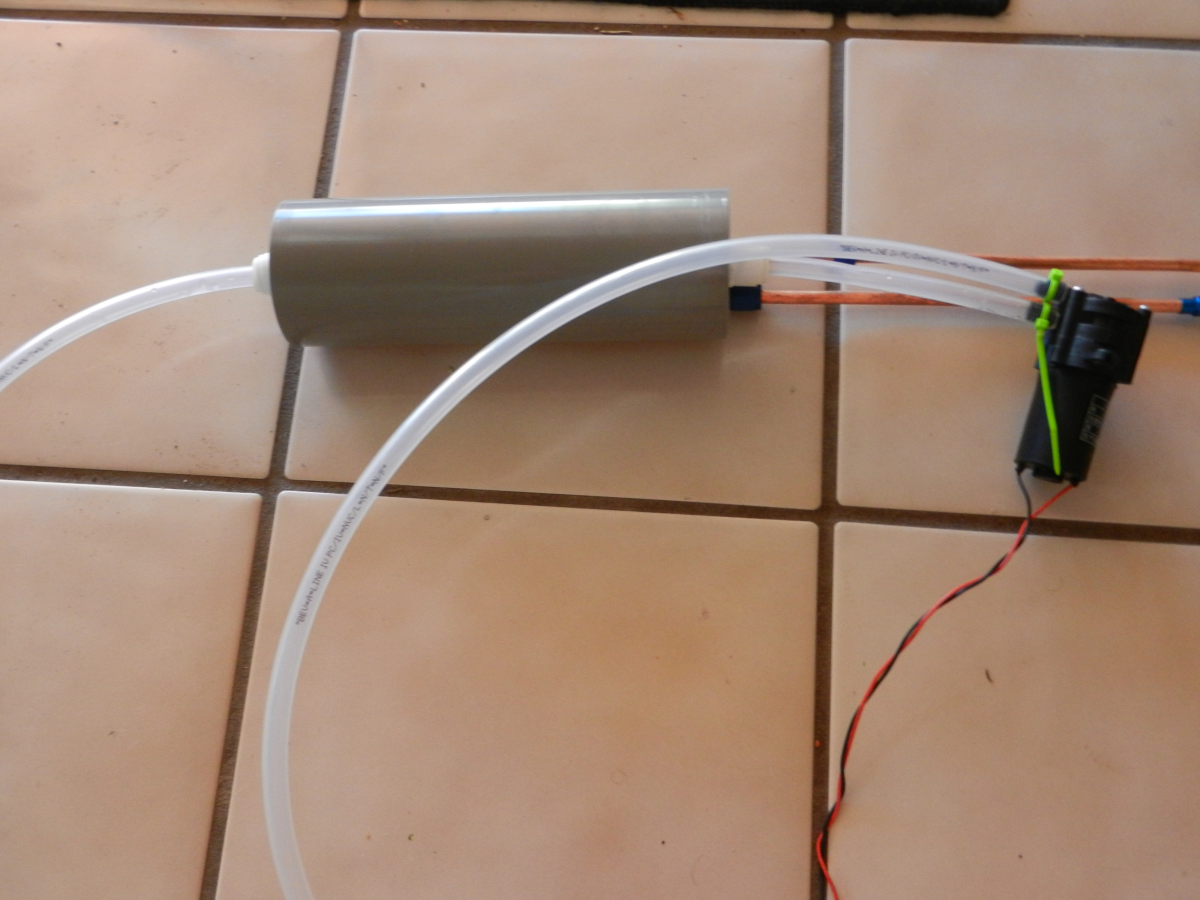
    Here is how I made my Heat Exchanger, which basically has three parts: evaporator, chamber for evaporator and coolant liquid to mix, and a way to seal the chamber that will allow tubing and refrigeration connections. Below is a very basic diagram showing how the Heat Exchanger works. The evaporator coil gets cold when the refrigeration system is running. Inside, the chamber is filled with liquid coolant. The coolant is pumped through the chamber that contains the cold evaporator which mixes the coolant through the evaporator channels cooling the liquid as it is pumped out of the chamber. The evaporator coil is built so that the coolant can't just flow straight past the coil. This would be inefficient and give the coolant inadequate contact time with the evaporator coils.

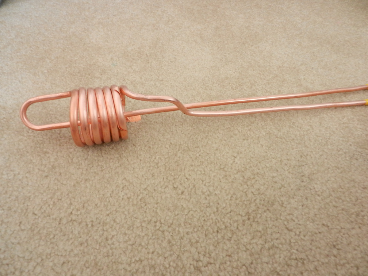
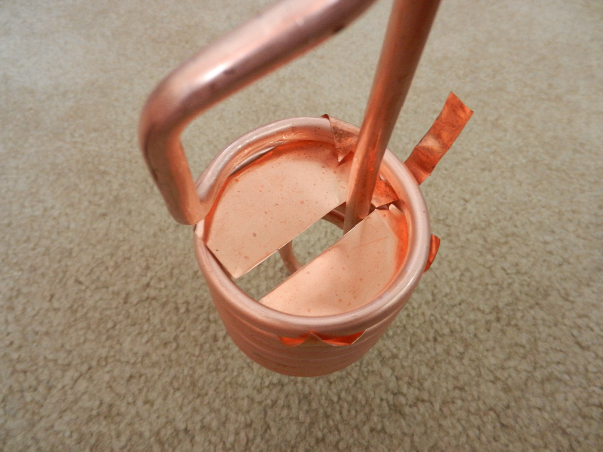
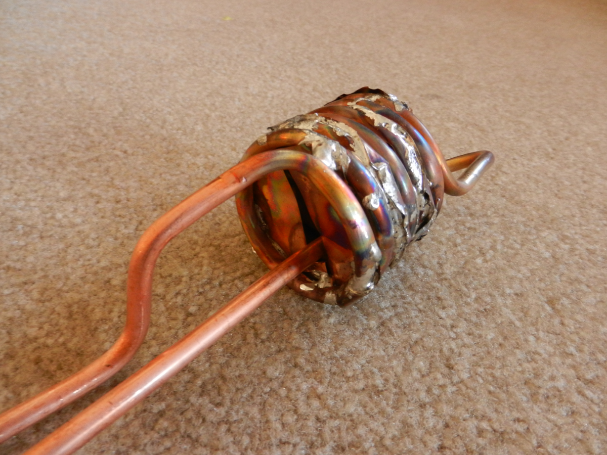
    The photo series below shows how I made the evaporator coil and then soldered in the 5mil copper sheets to make coolant channels that allow the coolant to flow through the evaporator coil. This gives the coolant adequate time to cool down since it is now in contact with the coils longer.

    Above is the overview of the evaporator coil.

    First copper plate to make the coolant channels

    Coolant channel soldered in place.

    Other end of the coolant channel.

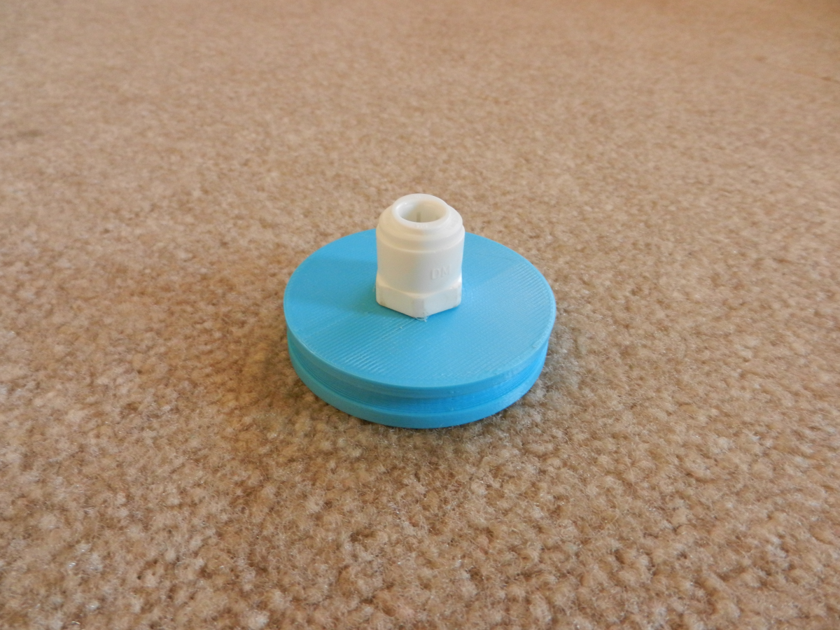
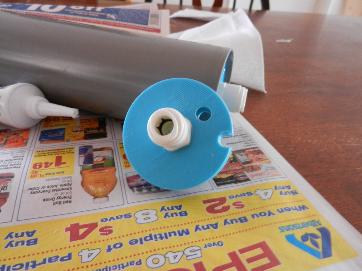
    Next, I used my 3D printer and made a set of end caps.

    End cap with coolant port only.

    Other end with coolant port and two openings for the refrigeration lines.

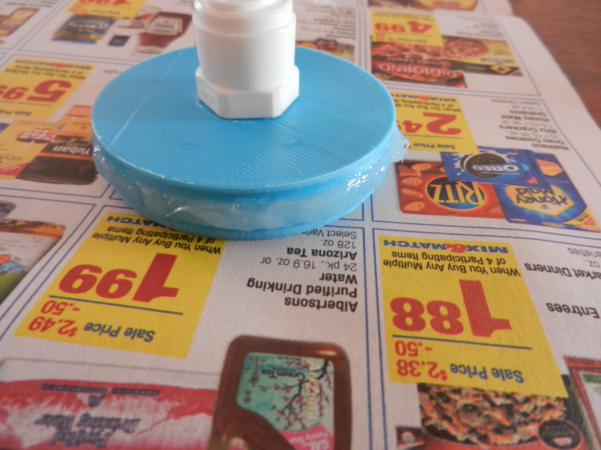
    Put 100% silicone around the gasket groove to seal everything up.

    End part installed and sealed with silicone.

    Other end sealed with silicone.

    An overview of the whole system.

    The chamber is just a G-10 high powered rocket body tube from Public Missile.

    Heat Exchanger test

  • System design and preliminary components list

    extremerockets08/17/2015 at 20:08 0 comments

    The diagrams below are to show what I am working toward in the next couple months. I am going to be working toward finishing the refrigeration system. The refrigeration system will be integrated into a 3D printed housing that will be mounted on the backpack. I hope to also have the battery power system prototyped and running the compressor. Lastly, I hope to have some form of liquid cooling system up and running with the servo vales running.

    Above shows the overall prototype system.

    Above shows the battery power system. It consists of the battery balancer, charger, and boost converter.

    Above is the mini refrigeration system with the mini Aspen compressor.

    Above is the liquid cooling system diagram with the servo valves that control where and when each cooling circuit in the shirt gets coolant circulated through them.

    This is a very preliminary parts list. I will be updating this list in the coming months as I get the build going.

    Part
    Supply CompanyQuantity
    Q4-24-5100 mini compressorAspen Compressor1
    Micro Condenser C4x4x1.25S/CU-STAlcoil1
    Cougar CF-V12H 1200rpm 17.7dB 12V FanNewegg1
    2712T45 0.010" orificeMcMaster-carr1
    Needle valveMcMaster-carr1
    AC121 High side AC fittingSpendLessAutoParts.com1
    AC122 Low side AC fittingSpendLessAutoParts.com1

    981504 -4 union ANplumbing.com8
    581804 -4 B-nutANplumbing.com4
    581904 -4 tube sleeveANplumbing.com4
    Turnigy 5000mAh 20-30C Li-Po BatteryHobby Kings2
    MSP430F5152Digi-Key5
    LT3790 Buck/Boost convertersDigi-Key2

    Compressor Restrictions as stated from Aspen Compressor:

    The compressor shall not be directly used for Electronics Cooling applications where the end user is a military, law enforcement or civil defense (local, regional or national) entity or personnel anywhere in the world.

  • Expansion valve and prototype coil

    extremerockets08/17/2015 at 19:11 0 comments

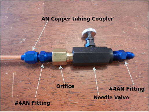
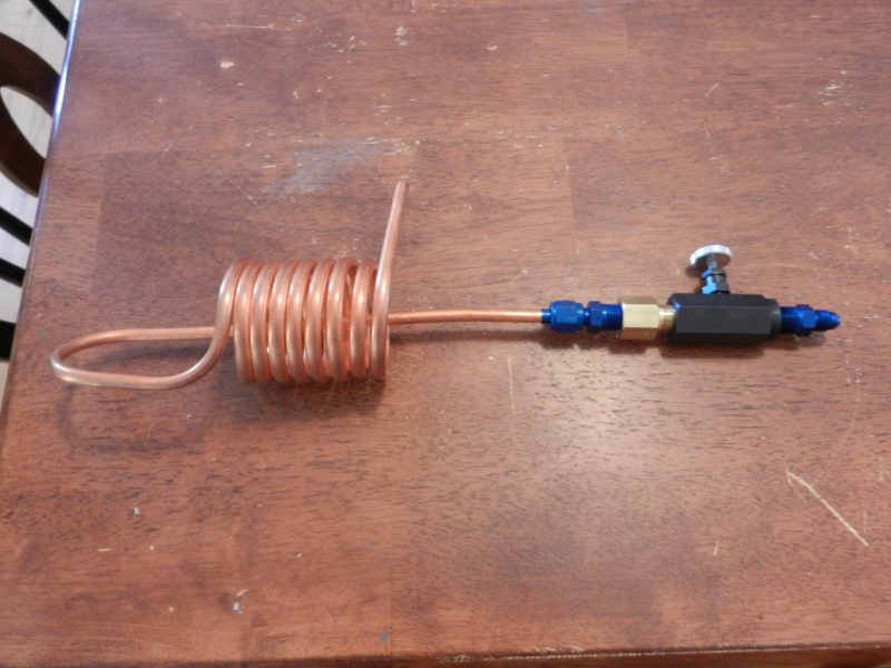
    This is my prototype expansion valve that I have made for the refrigeration system. I have incorporated both a flow control needle valve and a 0.010" flow controlling orifice. The idea behind the orifice is to make the liquid R134A spray into the evaporator coil. I added the needle valve so that I can experiment with different flow rates of R134A entering the evaporator coil. As stated in previous project logs, I am using AN fittings to connect the various parts of the refrigeration system together.

    As pictured above is the whole expansion valve and the evaporator coil. I am going to make a new smaller coil that will fit better inside the heat exchanger tube. This is just to give an idea of how the system is progressing.

  • The New Plan!

    extremerockets08/11/2015 at 01:17 0 comments

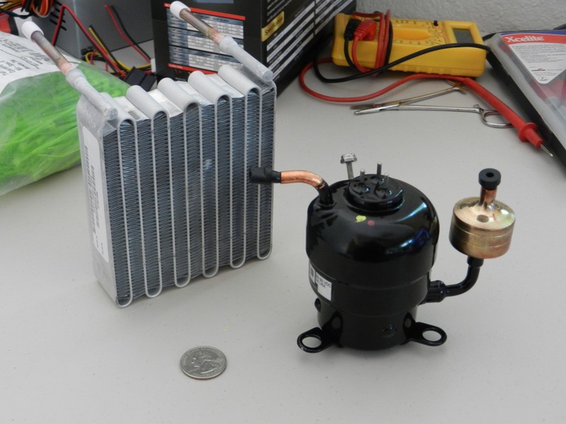
    As stated in the last project log detailing the TEC experiment, this has become a dead end for this application. I am now going with a new plan of using phase change for my source of cooling. I am going to make a mini refrigeration unit. This system will be capable of 360W of cooling power. With the mini compressor I will be putting roughly the same amount of power into the system as with the TEC's but I will be getting 360 watts of cooling power. This will be a vast improvement in power efficiency because I will not need to run the compressor all the time to reach my cooling temperature goals. The mini compressor is going to run 24V with a max current consumption of 10amps. The picture below shows the mini compressor and the micro condenser. I am going to use R134A refrigerant.

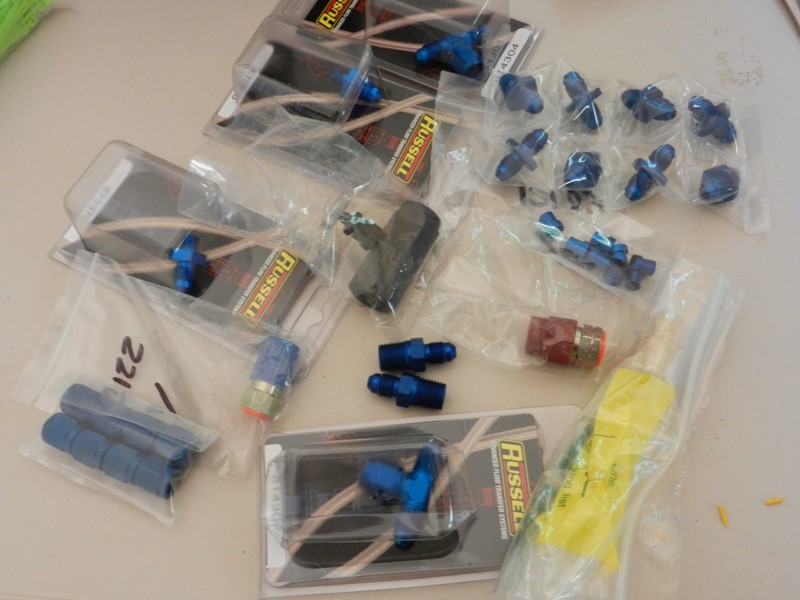
    In an attempt to get away from the complexities of HVAC brazing I have decided to use AN fittings to connect up the refrigeration system. The picture below shows the AN fittings that I am going to use.

  • TEC Experiment Failed

    extremerockets08/09/2015 at 21:47 0 comments

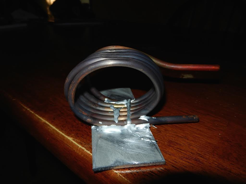
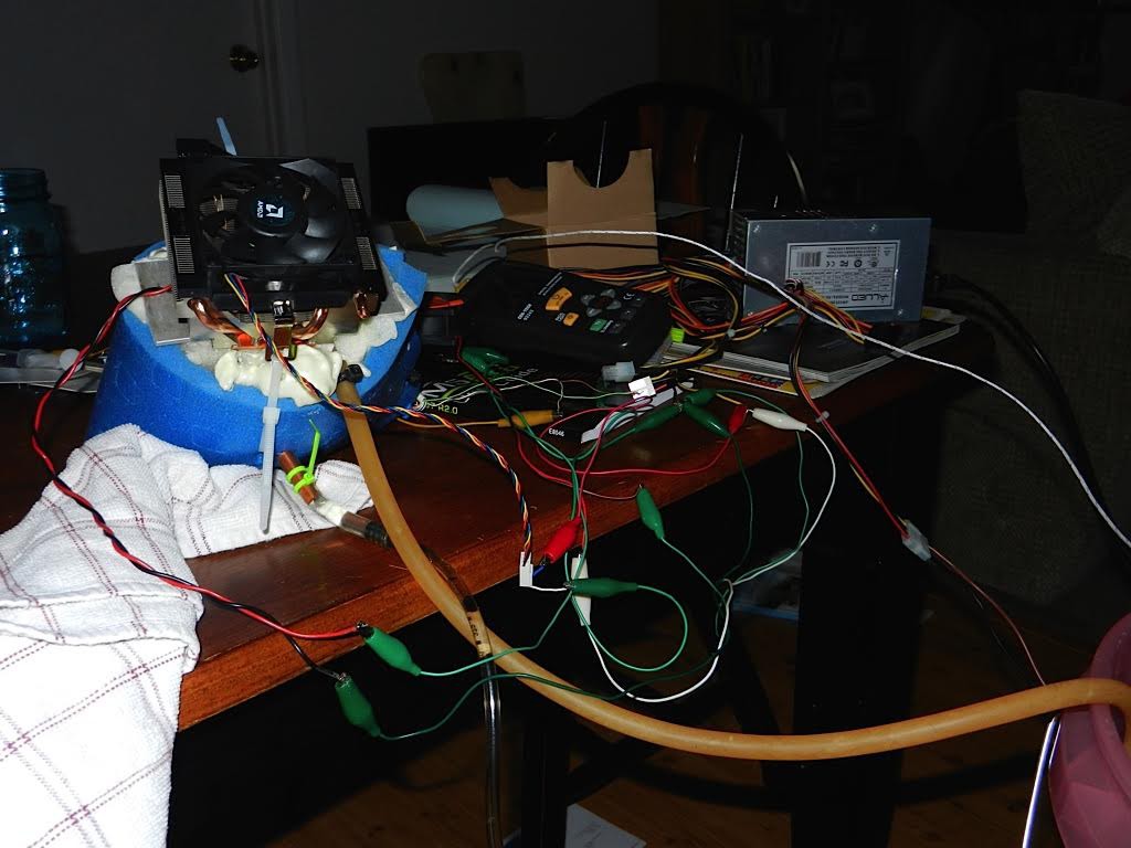
    This project log is an overview of a TEC experiment I performed. My experiment was a quick test and not the most elegant way to run a TEC. I wanted to see if this plan was going to pan out without investing a huge amount of time. First, I made a copper coil with an aluminium plate solder/brazed to the copper coil. This did not go very well but I think I got it to work.

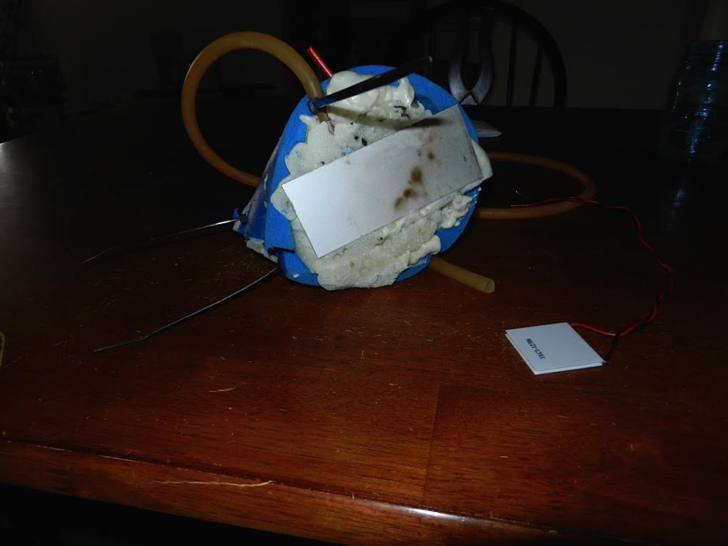
    The point of this cooling coil was to attach the TEC to the bottom of the aluminium plate and that would make the copper cold which would make the water flowing through the coil cold. The next step was to insulate the copper coil. This was done by using expandable foam and an insulating foam pad wrapped around the outside.

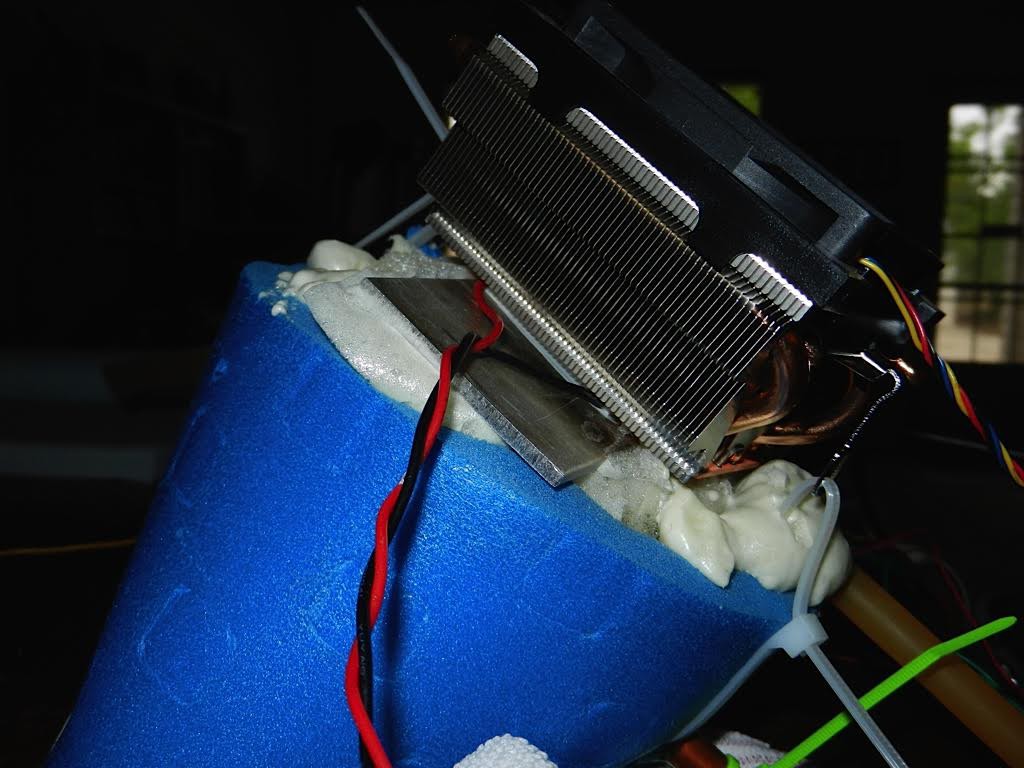
    Next I needed to mount the TEC's cold side to the aluminium plate and the TEC's hot side to a heatsink. I used thermal compound on both sides of the TEC and sandwiched the TEC as shown below.

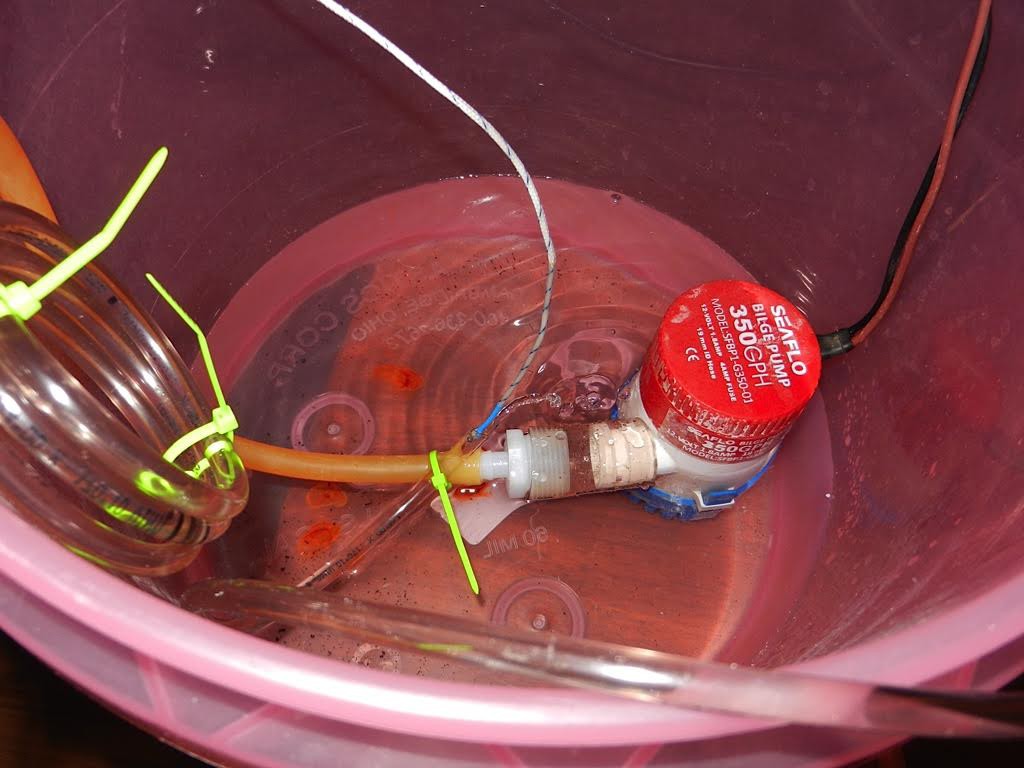
    Next I hooked the whole experiment up. I used an ATX power supply to power everything. I used a 100W power resistor to limit the current to the TEC. I used the 12V rail from the power supply to power the TEC with the power resistor in series. I think this worked okay for this experiment but not for a real application as I burned a lot of power in the resistor. I used a submersible 12V water pump to circulate the water into the cooling coil. Lastly I had a thermocouple at the water outlet to measure how much the water had been cooled.

    The whole purpose of this experiment was to see how much cooling I could get from a single TEC unit. The results were as I thought they would be. This experiment turned out unsatisfactory results. I was putting about 72 watts of power into the TEC, which is 12V X 6Amps. This only gave about ten degrees below ambient. This shows that they are truly inefficient devices. I am no longer pursuing using TECs for this project.

View all 9 project logs

Enjoy this project?

Share

Discussions

AdamH wrote 02/12/2016 at 05:24 point

I would first like to say that this project made me sign up here. I have a few suggestions. You have the discharge line tie into the bottom of the condenser and the liquid line comes out the top. The way a condenser works is the hot super heated gas from the compressor enters on one end, the gas condenses into liquid partway through before it exits as straight up liquid. You need to switch the lines on the condenser so the hot gas enters the top and the liquid comes out the bottom port. Also regarding the extremely overpriced Aspen compressors... I called aspen 3 years ago to get a price on a compressor, it was $250 with the controller. I called them 2 years later to order one, they told me the cost went up to $450. When I asked them why the cost was so much more over a span of 24 months, they told me they needed to hire more Tech support staff to handle phone calls about compressor issues. Seems a little ridiculous. I have found some alternatives for much less. Rigid Auto Parts makes very similar compressors that can be found here http://www.aliexpress.com/store/product/High-efficiency-R134A-DC-Tiny-Refrigeration-Compressor-150W-400W-for-car-mini-portable-fridge-vessel-camping/331602_1350395498.html

Here is a site where a guy experiments with both the Aspen compressor and the Rigid compressor.  http://www.mytekcontrols.com/

Good luck with this project.

  Are you sure? yes | no

frolickingdirtchild2000 wrote 09/16/2015 at 17:45 point

I don't know if you've considered this but RV refrigerators cool by heating chemicals in a closed loop. Using your TEC's to increase  heat after the cool side and and provide cooling on the portion providing cooling you could reduce the necessary power and battery pack size. If you can reduce size on the conventional RV fridge system, and mitigate the leveling issue.

  Are you sure? yes | no

Erin wrote 08/30/2015 at 14:46 point

I'm really interested in following this project.  I'm quite active and do a lot of work outdoors in the summer.  I found out that if I could just keep cool, I could work like a dog and not sweat a drop.  I experimented with aquarium tubing lining a cap and vest that was hooked to a garden faucet.  I was out in direct sunlight and almost got chilled.  It worked great until a splice broke and completely soaked my overalls.  LOL!  This would be a great project for even those without MS because the safety factor for everyone as well as increased productivity during hot weather would be a great thing.  Thanks for pursuing this.

  Are you sure? yes | no

extremerockets wrote 08/30/2015 at 16:00 point

Thanks Erin! Yeah it's not just for MS but anyone that has to work in hot environments or struggle with hot weather. 

  Are you sure? yes | no

Tom Walter wrote 08/29/2015 at 14:16 point

Nice project!  

Few random thoughts: Cooling shirt for racing (12 quart cooler is too big to lug around, but to join family at a beach setting maybe reasonable)

https://www.pegasusautoracing.com/productdetails.asp?RecId=6427&gclid=Cj0KEQjwsIWvBRCnzevvor2g4L8BEiQAAN234ajdoMyNdnAC3tf_ArL0l0cFYzAX8h8RaoEeNe5H55UaAtlW8P8HAQ

Also, ideal for folks with MS to read a book on a computer and flip pages:

www.cameramouse.org  (no charge for that program)

I still do some machining. Hard to get anything done in the shop on 100 degree days, as shop in 120F.  Work 20 minutes, sit an AC room for 20. Hence that Pegasus Auto Racing cooler looks tempting.  PM if you need something simple (aluminum manifold for those fittings).

For anyone around Austin that needs a custom "notebook stand" for someone with MS or Parkinson's let me know as I have a few ideas (I have Parkinson's, holding a book is difficult at times)

  Are you sure? yes | no

andres ortiz wrote 08/29/2015 at 06:53 point

Had you looked into stirling coolers? I remember coleman used to sell a cooler for camping that had a nice all in one unit that could be salvaged.

  Are you sure? yes | no

extremerockets wrote 08/29/2015 at 19:33 point
I think they would be to big and maybe low efficiency. 

  Are you sure? yes | no

andres ortiz wrote 08/29/2015 at 06:48 point

How much did that compressor cost?

  Are you sure? yes | no

extremerockets wrote 08/29/2015 at 19:31 point
A lot! Aspen Compressor minimum order is 2. So it was a little over 1K in cost. Hopefully the cost will come down when ordering in bulk quantity.

  Are you sure? yes | no

James Newton wrote 09/03/2015 at 21:29 point

Ouch... $500 will buy a lot of LiON cells to run a low efficiency peltier... on the other hand... then you have to lug around all those batteries. 

I suppose Hilch Vortex tubes aren't any more efficient:

https://en.wikipedia.org/wiki/Vortex_tube#Efficiency

but then you don't have to carry coils, or coolant... just uses air.

  Are you sure? yes | no

sir_sleepless wrote 04/02/2015 at 05:14 point

Have you chosen a specific Peltier module to use yet?

  Are you sure? yes | no

extremerockets wrote 04/03/2015 at 17:46 point
I have two cheap Peltier modules that I got off ebay. I plan on looking to find better ones.

  Are you sure? yes | no

sir_sleepless wrote 04/04/2015 at 02:08 point

Okay.  I was just wondering how much heat flow they were capable of sustaining on your power budget.  Do you know how much cooling you'll need to supplement the wearer's perspiration?  Looking at http://hyperphysics.phy-astr.gsu.edu/hbase/thermo/coobod.html#c2 suggests you might need quite a bit; going off the data sheet for one TEC (http://www.mouser.com/ds/2/223/THR-DS-CP14,127,10,L1,W4.5-522657.pdf) and assuming heat current Q is linear with area, I think you might get about 100 thermal watts of cooling with two 2-inch TECs of similar design (assuming my math is right).

  Are you sure? yes | no

extremerockets wrote 04/05/2015 at 21:10 point
Honestly I was going to try it out by a series of experiments. This is very interesting. This is really what I am trying to make. 

http://en.wikipedia.org/wiki/Liquid_Cooling_and_Ventilation_Garment

  Are you sure? yes | no

sir_sleepless wrote 04/06/2015 at 04:21 point

Experimenting sounds like an excellent first step; I only suspect you'll need more heat flow than your current modules will provide.  Good luck!

  Are you sure? yes | no

M. Bindhammer wrote 04/30/2015 at 13:40 point

This was also my first thought. Will folow your project. Good luck

  Are you sure? yes | no

Similar Projects

Does this project spark your interest?

Become a member to follow this project and never miss any updates