pastcompute
-
Brief update - ESP8266 plus LoRa
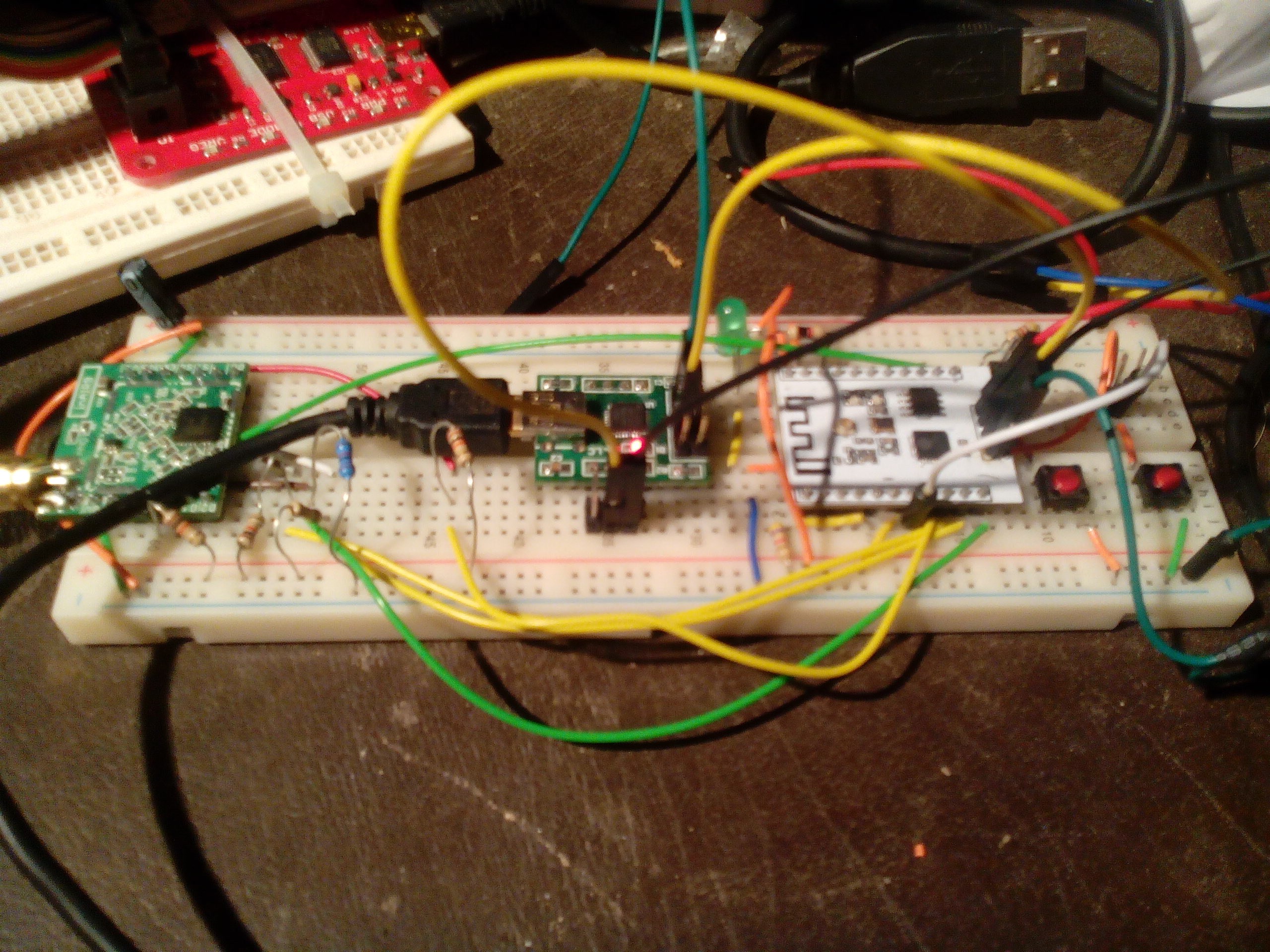
07/01/2015 at 12:23 • 1 commentSo I now have an ESP8266 controlling the SX1276 module, successfully sending or receiving a beacon. This is working much more reliably as a receiver (as does the carambola2) compared to the bus pirate
This weekend is GovHack Unleashed, so not much happening for a few days.
Next step is solder the pin header onto the TeensyLC and test that I didn't accidentally put any ESP8266 specific assumptions in the code.
Then it will be on to implementing the end node MQTT-SN sensor transmissions, and hopefully soon, building up a board when the OshPark adaptor board arrives.

The picture from left to right shows the SX1276 inAir9, a CP2102 using RTS &c for programming control and ESP201 module The carambola2 with the other SX1276 is about a meter away. Only 9999 meters left to go!
-
Status update
06/26/2015 at 11:28 • 0 commentsLife has been hectic recently, and also we have been waiting some parts.
The plan is to complete the Carambola node and build the teensy node once the next circuit board arrives, and start conducting MQTT-SN experiments out in a real paddock :-) Hopefully by the end of July we will be in a position to bolt a module in a box to my back fence and start doing some ranging measurements.
-
Another PCB : building a network on an oily rag
06/15/2015 at 13:12 • 0 commentsSo far I have prototyped the MQTT_SN code and have the software communicating over radio between OpenWRT and a BusPirate. However, the BusPirate with an extra serial layer between SPI and the software is not fast enough and often drops messages. So we need to ratchet up and build a link between two Linux/OpenWRT direct SPI systems or OpenWRT and a MCU module like the ESP8266 or Teensy.
I only have one Carambola2, and the lead time / cost for more or similar alternatives is more than we would like at the moment.
We have a few Raspberry PI, plus model A are cheaply and very quickly available in Australia. The Raspberry Pi though probably will use the most power so is best suited for the farmhouse.
We do have several ESP201 modules, and now a Teensy LC on hand (thanks Hackaday!)
So what to do... hardware costs $$ and lead time, whereas software is just code... (and time, but not waiting time!)
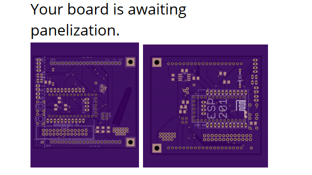
So I designed a second board that the SX1276 carambola2 shield plugs into that allows the shield to connect to either a Raspberry PI, a Teensy LC or an ESP201 (not all at once though!). Thanks to the Hackaday OshPark prize they are nice and purple as well!
To work with a Pi just requires a Raspberry Pi running OpenWRT and a 26-pin connector soldered to the board.
To work with the ESP201 requires a variety of pullup resistors, and the programming switches / connections for a CP2102 or FTDI adaptor, etc. Also the ESP201 is one GPIO short so it needs a i2c to 1-wire adaptor, DS2482
To work with the Teensy, like the PI should just require the connectors.
The ESP201 and the Teensy mount on the underside relative to the SX1276 board so that there is room.
-
A Quick First Post
06/10/2015 at 13:14 • 0 commentsI have been hiding in the background for a while being pre-occupied with other things (Life), but am taking the time to post what I am up to. I have been busy working on the design of an eventually accurate digital rain gauge. Rainfall measurement is important in agriculture and a lot of activities and planning are related to rainfall. Current measurements of rain involve travel to manually read graduated cylinder gauges. These tell you how much rain fell since you last measured it. Helpful and in most cases good enough, but labour intensive.
I have looked at many different digital rain gauge designs and settled on the tipping bucket gauge. I plan t make my own with an 8" funnel and have each tip represent .25mm of rainfall. I will use 150mm stormwater pipe for the gauge body. I intend to have the water go to a collector so that I can check the accuracy of the digital mechanism. For the tipping bucket I am considering making the prototype from some unetched copper clad board.
The electronic side of the gauge is a work in progress at this point. I am building the prototype with an Arduino nano using the Atmel 328P chip. This will allow for versatility in data output. For the initial prototype communication I will use an ESP8266 module with the MQTT client firmware. This will be fed by the Nano. The Nano may become an IC2 slave when we start merging the sensors and functions and a custom PCB will be designed to combine things nicely. The gauge will work by collecting rain in a tipping bucket design and counting how many tips occur over a given period of time. I may use the timer function of the Atmel chip to gauge how long between tips to give an indication of rainfall intensity. This may help for calibration. It will be nice for my records to include this information as rainfall intensity can make a difference to many aspects of agriculture.
At this point I have all of the components I need to make the first prototype and have the nano and a hall effect sensor on a breadboard outputting data over the com port for each hall effect sensor activation. I plan test the hall effect sensor's latching function better as that will influence my bucket design, which will be the next step. My next update should include some pictures and hopefully some progress.
-
Incremental steps. 20km^H^H20cm!
06/08/2015 at 13:01 • 0 commentsWell, I'm finally subscribed to MQTT-SN topics over a radio distance of 20 cm...
I'm losing about 40% of messages output by my beacon publisher, mainly due to an occasional dropped message about only 10% of the time (due to the Bus Pirate end not being as reliable as the embedded Linux spidev) seeming to interrupt the 'flow' of MQTT. My bridge is currently dumb, doing nothing other than a checksum. I thought that MQTT-SN would be more robust than that, being designed for such links, so I probably should read the spec now! In the medium term that wont be a problem anymore once I can replace the bus Pirate completely.
We had a planning meeting over the long weekend and refined the architecture a bit, so the main diagrams are going to need to be updated.
We'll probably end up with three node types.
First, the farmstead, with Ethernet and no requirement for low power - we'll probably use a Raspberry Pi because these can be had at short lead time here.
Second, a more powerful fencepost with store and forward capability, as this topology maps best onto typical farms in this area. The Carambola 2 will be put to use in this capacity as the first deployed node, Linux powering store-and-forward with backup logging to USB, and a suite of additional sensors including USB goodies that wont necessarily be deployed to the leaves, and if required more than one radio. This will need a largish solar panel, but will be better for low power than a Raspberry Pi.
Currently the comms is all effectively dumb half duplex with no media access control, and initially for multiple spokes we'll drive multiple radios on the store and forward node. Longer term of course we need to upgrade to a proper link protocol, maybe LoRa or Dash7, but that can be done in software in the longer term future.
The leaf fencepost nodes we are now looking at coupling an ESP8266 (201) with the SX1276, they have enough grunt to drive it but are much cheaper than the Linux modules, and still provide wifi for a farmer to drive up and communicate with using a phone. At this stage the fencepost nodes still going to provide wifi to the ground sensors yet have enough GPIO be able to pivot to 433MHz.
Finally we are going to use Arduino Nanos or maybe the new uHex Atmel powered models for low power sensor applications where a MCU cant sleep (like rain gauges) slaved from the fencepost nodes.
All this is of course a work in progress and subject to further change!
Soon hopefully James will be providing an update one of the whether sensors we are designing.
-
Keeping it educational
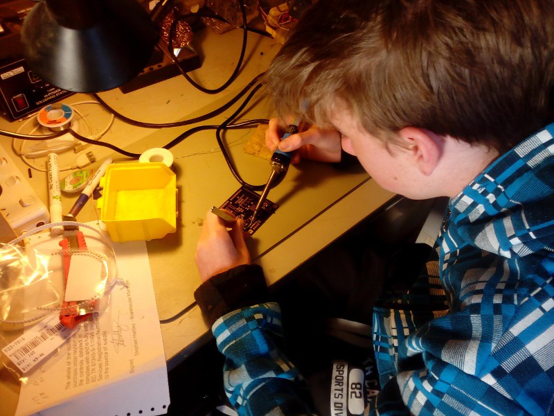
06/06/2015 at 11:47 • 0 commentsSo today we finally had a chance to work on the first control board, the radio and I/O shield for the Carambola2.
I only learned how to solder SMD components myself 6 months ago, so this was a good chance to teach Mr.14 as well :-)
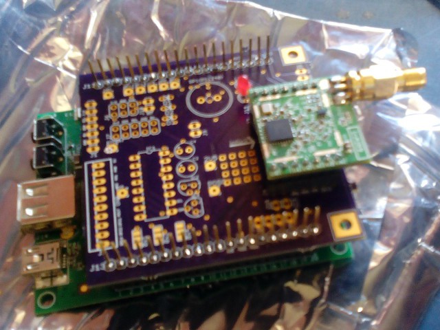
Everything lined up perfectly! The only bug, as it turned out, was that I had the i2c SDA and SCL lines swapped on the PCB, aargh!
The solution is easy thankfully, as i2c on the Carambola2 is simply the Linux i2c over GPIO driver, so all I had to do to fix it was swap the GPIO on the module load command.
The purple OSHPark PCB does look pretty good!
Next step is to hook up the radio. I have been making progress with the software; we are now going to use MQTT-SN as the protocol, with a bit of luck we might be sending messages by the end of the long weekend.
Once we manage to get some reliable comms going then we can come back and populate some of the general I/O on the shield.
-
Architectural Refinement
05/24/2015 at 13:24 • 0 commentsNow that I have two inAir9 modules talking to each other on my bench, I have been spending some more time considering architectural questions, while waiting for delivery of PCBs.
At this stage we are looking at using MQTT as the glue.
The fencepost will be running Linux, and either RSMB or mosquito. There will be a bridge process that is an MQTT client subscribing to wildcard and forwarding the data through the SX1276 to the next hop. By using the right MQTT hierarchy, store and forward should be scalable for the number of hubs we are looking at. The ground sensors will thus be publishing MQTT clients, and there will also be a publisher inside the fencepost for the weather sensors, etc. The far end is a second client that receives radio data and publishes the results.
To reduce bandwidth requirements, I envisage some kind of compression or rather binary translation layer, so that the SX1276 clients will have a small database of MQTT topic to binary code mappings, used to tag each message instead of a full topic.
-
Physical design
05/20/2015 at 23:25 • 0 commentsWe'll need to start on building some actual boxes soon. The fence post is on the critical path, so we'll probably go with some kind of plastic enclosure that we can seal the water out of.
If we decide to repurpose PVC pipe, or even if not, we will probably need to rig up some parts to hold circuit boards in place. Some 3-d printed components would come in useful there...
-
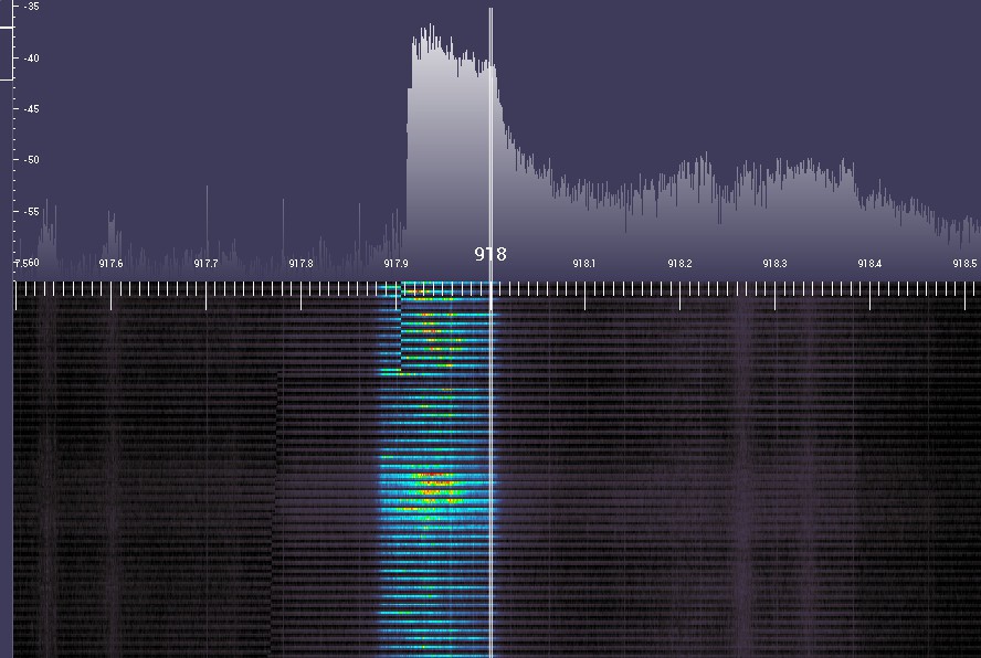
Its Alive! muwahaha (or not...)
05/17/2015 at 11:08 • 1 commentAn inAir9 sx1276 module transmitting a beacon (the text "Hello World") using LoRa mode at 918 MHz, 125kHz bandwidth and spreading factor 9. Roughly equivalent to a 4800 baud modem in terms of throughput...
Driven via a BusPirate in binary SPI mode.
Next test, using the Carambola2 with OpenWRT and spidev. I have developed the SX1276 code that communicates using an SPI abstract class, with both BusPirate and Linux spidev implementations so that _should_ hopefully be quite straightforward...
Note also the signal strength in the above picture is exaggerated - when I introduced a short delay between transmissions the colour dropped right off, i.e. stopped saturating the link. Also, I turned down the gain...
Without even using proper antennas (I hooked up a 2.4G antenna) I was able to see signal on the RTL through 3 stone walls and 50m out to the road, so a good start.
UPDATE
I have the beacon code working on both OpenWRT using spidev, and with the bus pirate now. So on to the receiver...
-
Your board is awaiting panelisation
05/11/2015 at 12:38 • 0 comments
SentriFarm
Solving a key farming problem: is it safe to harvest / spray / sow today? (+experiments with 'big' data in agriculture)