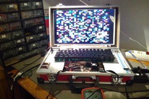
Megapixy: a 13" Retina-class screen on a boom arm.
Google's $1300 Chromebook Pixel has an awesome screen. i only want the screen.
Google's $1300 Chromebook Pixel has an awesome screen. i only want the screen.
To make the experience fit your profile, pick a username and tell us what interests you.
We found and based on your interests.
i am happy to announce that the Megapixy design files are now available online for your viewing/modding/hacking pleasure.
this took awhile. it turns out, when many of my design files are over a year old, i need quite a bit of time to organize them!
Megapixy is an adventure in sourcing parts. you will probably struggle to find the PCB receptacle for the IPEX micro-coaxial cable, as well as the cable itself. i have spares! contact me and i can help you.
have a great day :)
Tshen2 2015
i ended the last update with these two problems:
these are both chassis problems, which require chassis solutions. solutions i built in parallel with Giger board - such is iterative design.
at this point, i was designing my chassis with Eagle and doing all my own lasercutting at danger!awesome. my chassis was still two pieces of plywood screwed together. i wanted a quantum leap in fit and finish,
my Industrial Design friend, M, was in town, and we sketched silly ideas in an empty apartment.
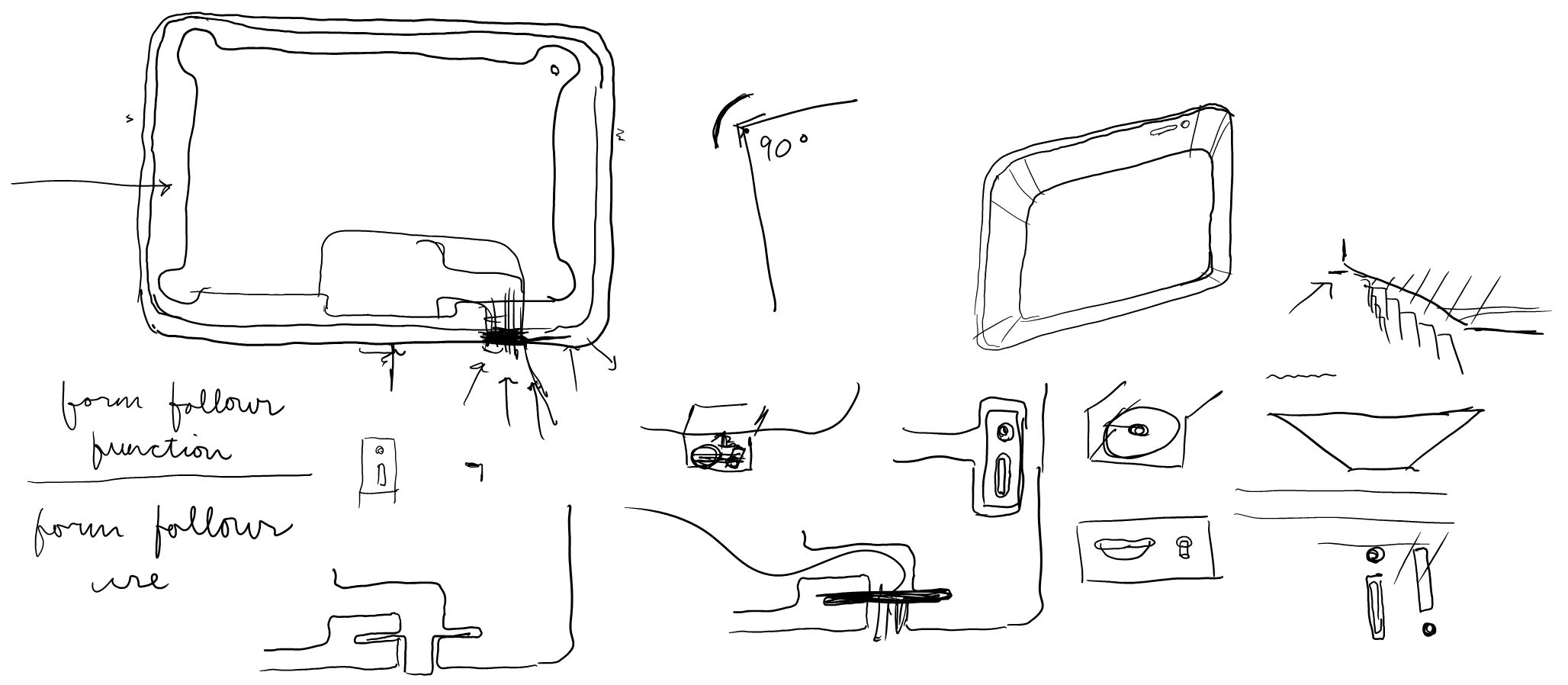
i seemed stuck on two opposing design requirements.
alright, M said, you need it to be thick. but can you make it look thin?
by chance, we were sketching on my tinycomputer - a great example of this illusion. Microsoft had to build a thick tinycomputer for thermal reasons, but they wanted it to look thin. so they bevelled the edges. the result is an 'infinity pool' effect, where the chassis depth cannot be seen from the front.
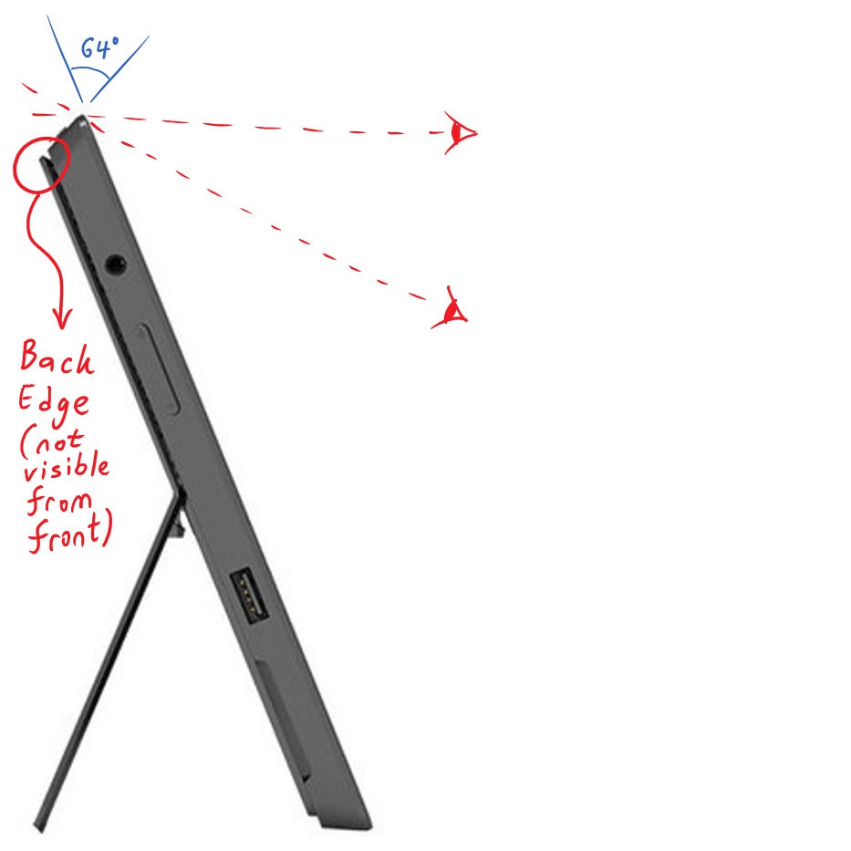
but it is not practical to create a smooth bevel with a lasercutter. could i CAD the whole chassis in 3D, and mill it out with a Shopbot?
so i downloaded a trial version of Rhinoceros.
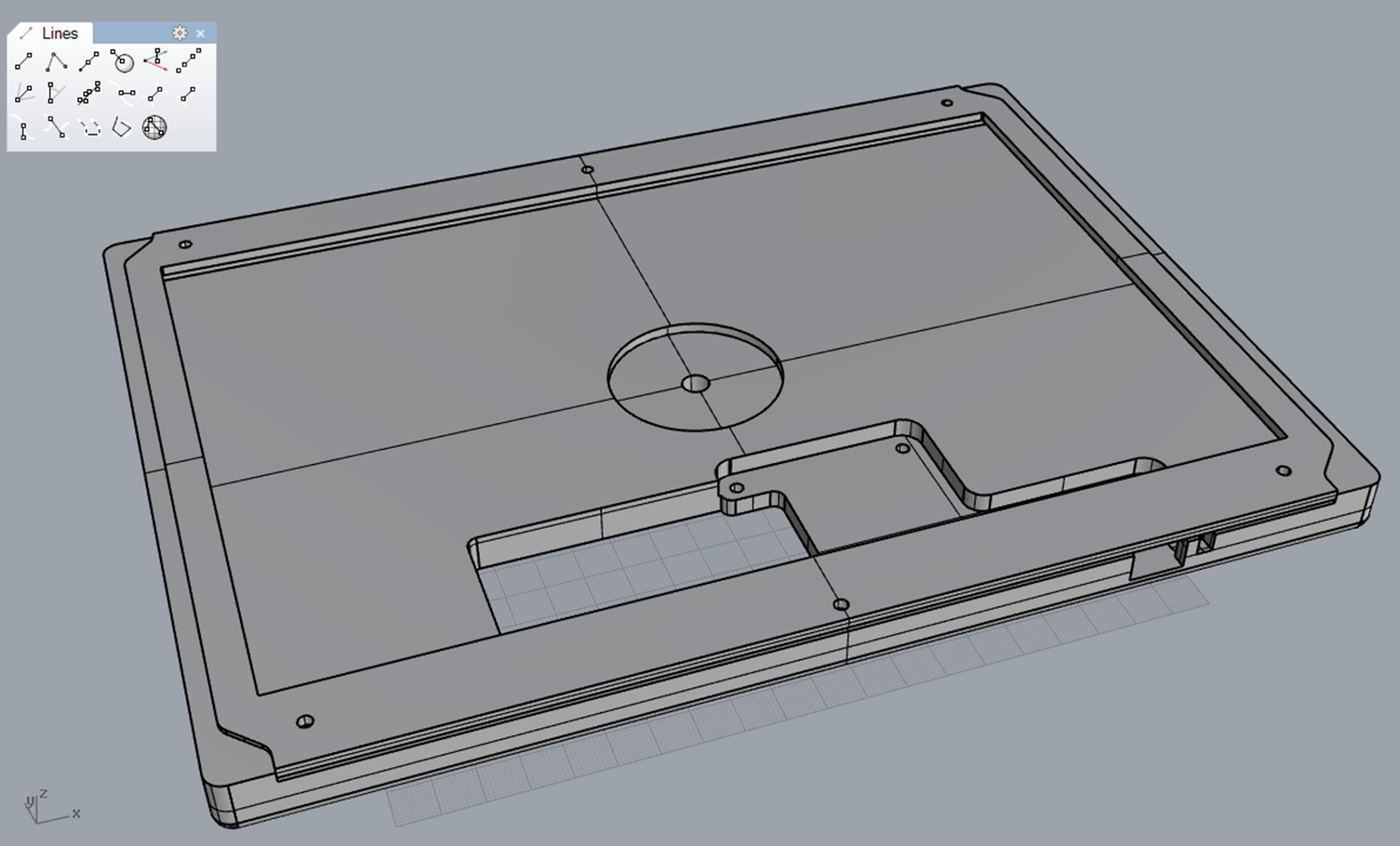
[attempt #1, modeled around the 'comma' board.]
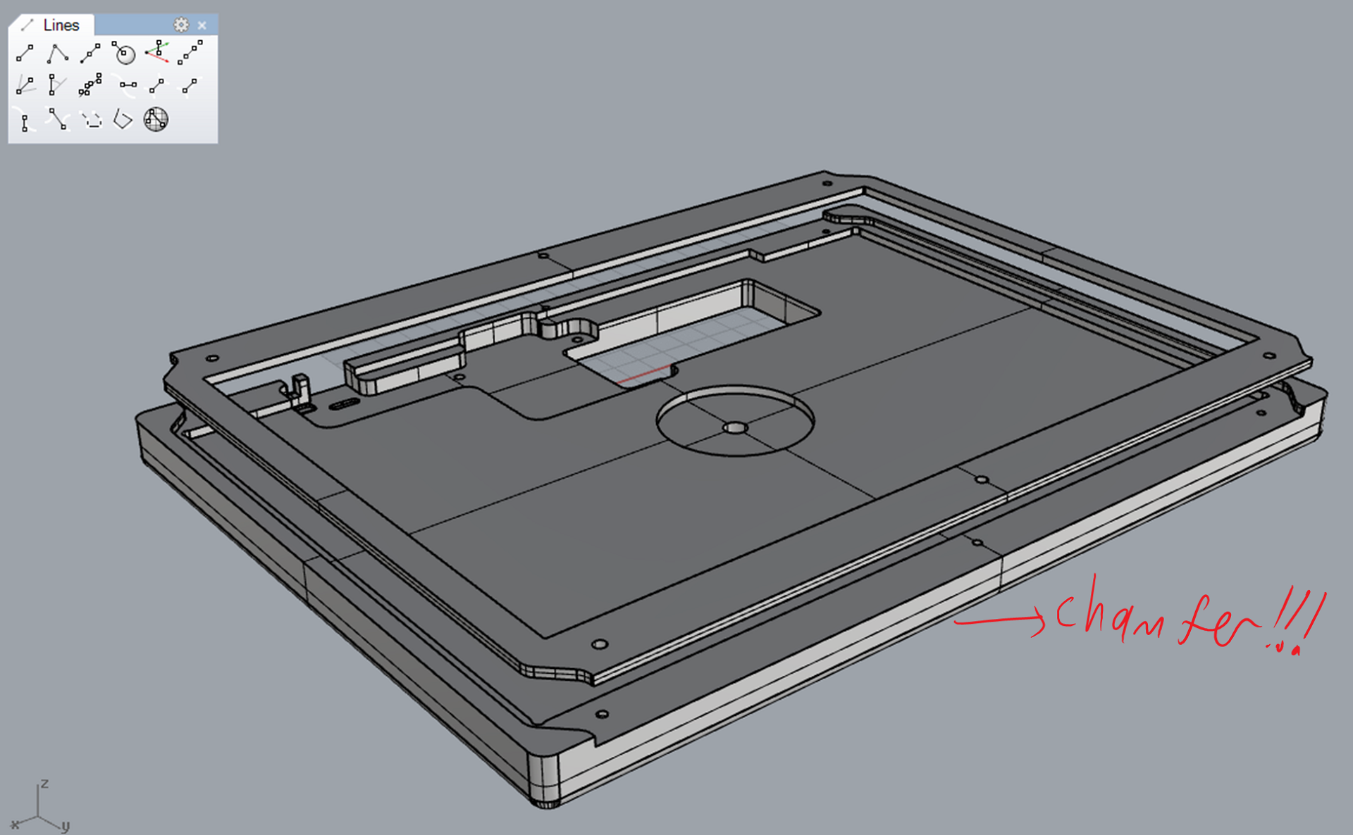
[rounded edges? no, we want chamfers! or bevels. same thing.]
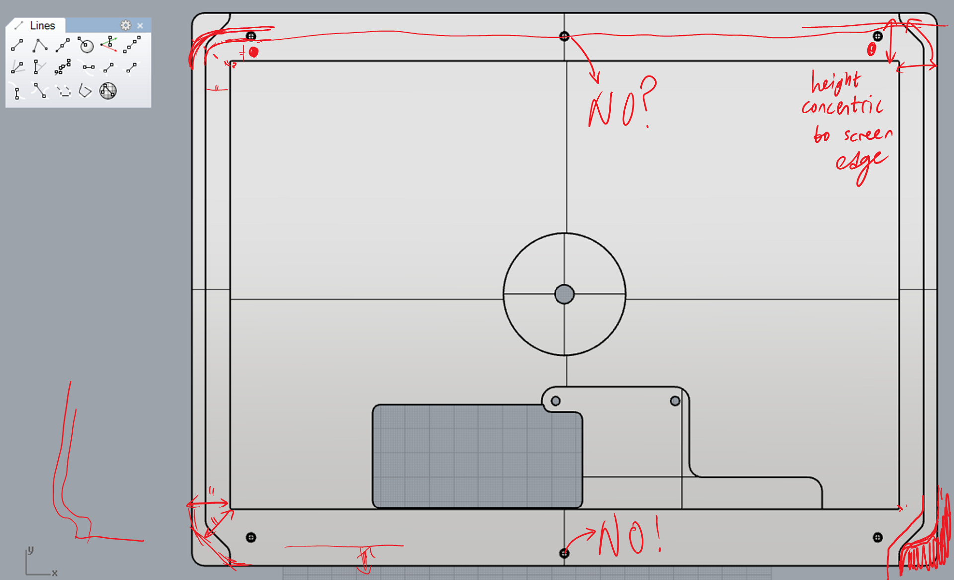
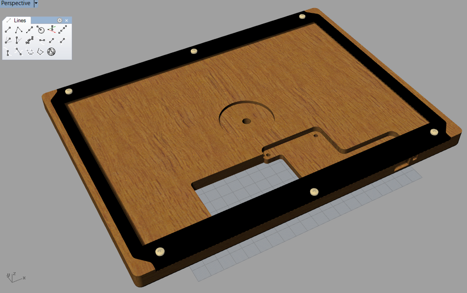
[with a bevel, the back edge drops away.]
i'd found a Shopbot at a local makerspace, and bought an expensive membership. but there was no parking, inconvenient hours, and mysterious closing times. and i spent hours upon hours just defining toolpaths in Mastercam, after which the tool would do something crazy anyways, and commit trepanation on my precious plywood. if rapid iterations create quality, i was getting none of it.
but! this was a fundamentally 2.5D design. to make quick prototypes, couldn't i just lasercut & stack several layers of plywood? i wouldn't be able to create the bevel, but at least i'd know if the basic dimensions were sound.
five stacked layers of plywood approximated my milling profile, so that's what i used.
[side profile: wood wood wood wood wood]
[pretending-to-be-a-Shopbot prototype, rear view.]
janky though it is, this prototype helped set some direction for the next:
so let's use nothing but a lasercutter, and get smart to make it work:
[side profile: acrylic acrylic acrylic wood wood acrylic]
[designed-to-be-lasercut chassis, front view. laser-etched recess for the T-nut in the middle.]
this was much better! the reflective/transmissive acrylic outer layers really complement the texture of bare wood underneath. but i'd been too aggressive with the laser-etching, and the too-thin acrylic was splintering under the screws. plus everything was still too thick & wasteful.
why was it so thick? because i needed a minimum wood thickness to attach the T-nut for the tripod mount. maybe i could use more wood under the tripod mount,...
Read more »let's detour into visual design - did you notice this on the previous update?

it's the Megapixy logo!
i like Megapixy, and i like making logos. go figure.
in the infinite possibility space of logo (and not-logo) design, some reason must be provided for why anything looks like anything. the Megapixy logo exists because:
with regards to 1, there's a little homage to the Displayport logo:

as for 2, the Megapixy logo also has a 3:2 ratio.

now back to engineering :D
brightness control should be easy, right? nope.
there's an ATtiny microcontroller on the 'comma' board which reads the brightness dial. the microcontroller creates a PWM signal which gates the backlight driver. it looks like this:

[block diagram of Megapixy brightness control (first try).]
some simple measures were taken to reduce electronic noise:
and then, an interesting bug. when the screen was on, i could hear a tiny whining sound!
and to explain that, i'll have to talk about PWM.

[cartoon of pulse-width modulation (PWM)]
pulse-width modulation (PWM) means controlling something with a series of on/off pulses. the perceived 'on-ness' (e.g. backlight brightness) is based on the fraction of time when the device is 'on'. this fraction is called the duty cycle. the on/off pattern repeats with a fixed frequency.
the backlight driver's on/off pulses were a PWM running at 500Hz. i was powering the Megapixy with a cheap 5V power supply, which was now having to supply more & less power on a 500Hz cycle. this caused my power supply to buzz audibly at 500Hz - the so-called 'coil noise'. how could i fix this?
i could make the sound inaudible by increasing the PWM frequency from 500Hz (repeating every 2ms) to 20kHz (repeating every 0.05ms).
inaudible to humans, anyway. some dogs might notice.
the problem is, the higher your PWM frequency, the shorter your 'on' pulses:
during each 'on' pulse, the backlight driver has to turn on and pump up the backlight voltage. this process takes about 0.01ms. if the backlight driver doesn't have enough time to turn on, it shuts down completely until the circuit is reset. with a 20kHz PWM, this places a 20% minimum duty cycle on my backlight brightness control.
why is this a problem? because people like their screens to be really dim at night!
a 20% to 100% brightness adjustment isn't good enough. so what can i do?
there's this other thing called pulse-frequency modulation (PFM):

[cartoon of pulse-frequency modulation (PFM)]
in PFM, the duration of each 'on' pulse is always the same. to reduce the duty cycle, you can increase the time between 'on' pulses. at very low duty cycles, you will have large gaps between each 'on' pulse, which means a lower (and perhaps audible) frequency.
but PFM is still worthwhile because you can reach a lower duty cycle (brightness) without shortening the 'on' pulse. this gives the backlight enough time to turn on, even at very low brightness settings.
neither PWM or PFM does exactly what i want, but can i combine them to solve my problem?
the power supply might make sounds in the lowest brightness settings, but at least i would have lower brightness settings.

[partitioning of brightness control into smoothly-transitioned PWM & PFM.]
getting a smooth transition requires a teeny bit of math.
[featuring a random notebook from a random hotel.]
the net result is a brightness dial which adjusts from 100% (silent) to 2% (almost silent).

[cartoon of hybrid PWM/PFM brightness control.]
that's enough about brightness control!
Let's revisit that photo from my last post:
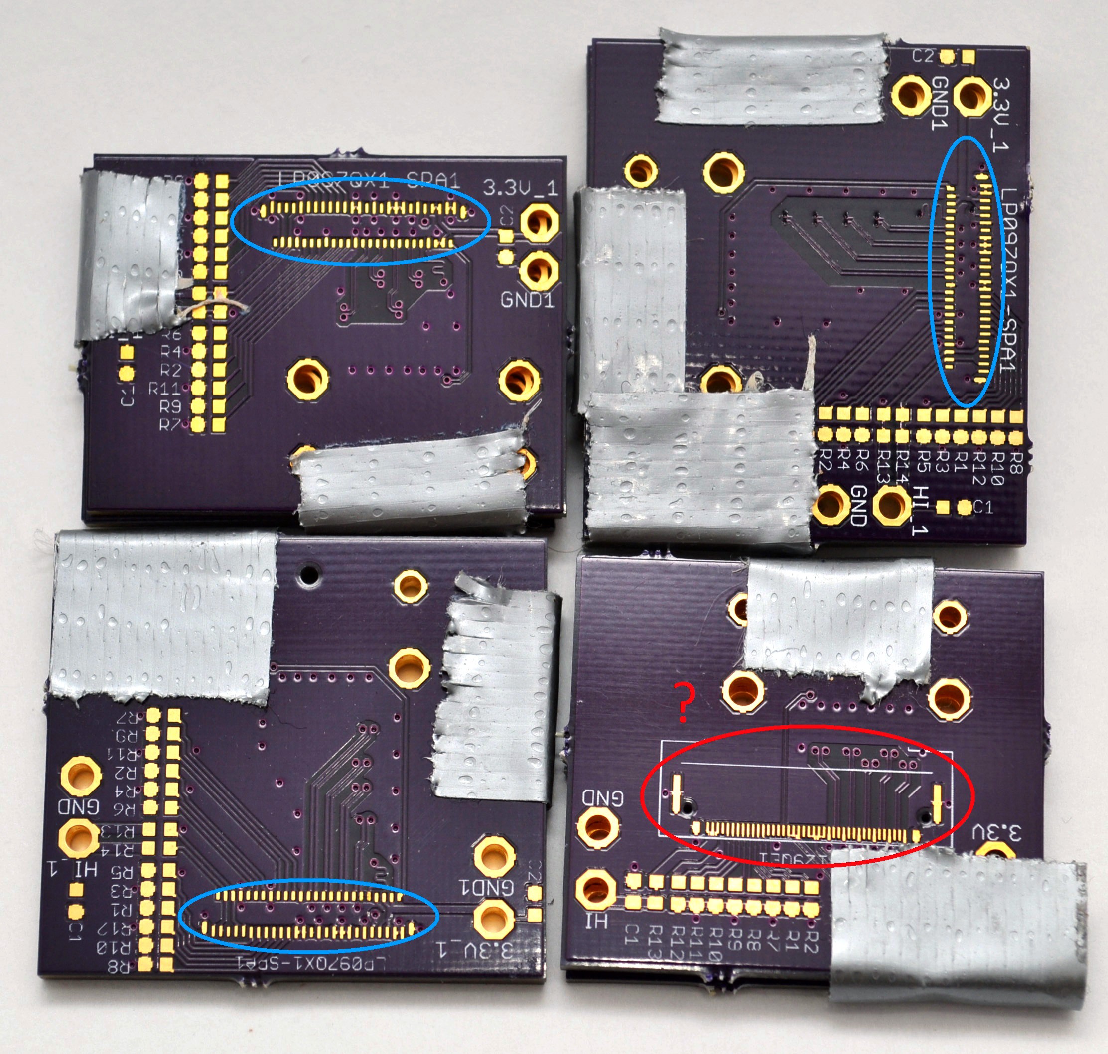
in my last post, i got the Retina iPad LCD panel working. but it was buggy & small & rather underwhelming.
although! that is just one LCD panel in a world full of LCD panels. my approach should work with any panel which communicates through embedded Displayport (eDP). what other eDP panels are easily obtained, which are more worthwhile to hack into?
bear in mind that this is 2013, a year where only Apple computers have screens worth giving a damn about.
except one other computer.
the Chromebook Pixel.
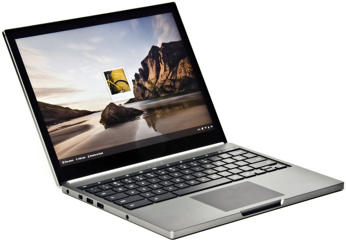
running a stunted operating system on beautiful hardware, the Chromebook Pixel is a mixed bag.
but that screen! it's glorious.
2560x1700 pixels, 13 inches across. that's 4.3 million pixels at 239 pixels per inch. 3:2 aspect ratio. massive contrast, huge viewing angles, colors out to infinity. it's IPS at its best.
what's more - unlike the Retina Macbook screens, the datasheet is available and the price is right. but no one else has done it - why? let's look at the datasheet:
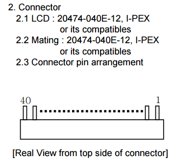
apparently it's got some whacko connector on there - an IPEX 20474-040E-12. how do you connect to that?
i'm guessing that this is where most hackers get stuck. but i really, really like screens, so i keep going.
so i randomly ping LCD cable manufacturers on Alibaba. they're all in China.
has anyone heard of the 20473-040T-10? can you take two of those and build me a 40-wide micro-coaxial array? everyone wants this, right?
and amazingly, someone gets back to me! they want a technical drawing. what?
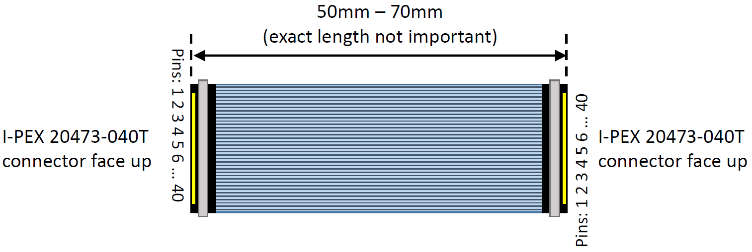
ok, i made that in Powerpoint. can i has cables?
they say i must pay for cables. but how? ESCROW?
no, not ESCROW! the correct answer is Paypal.
Paypal is how you send money to cable people in China.
[omg cables!]
[omg LCD with cables!]
now to make a crude test board which connects to the LCD panel through that cable.
and does the crude test board work?
yes it does!
even with long cables!
so obviously the Chromebook Pixel LCD panel is the way to go. and it's big enough that people might actually use it at a desk. so let's jettison all the internal-battery stuff, and focus on making a really solid wall-powered screen.
i'd like to point out: at this point in my career, i had no idea what i was doing.
i was supposed to design a circuit board? and some kind of chassis? to hold the screen in place?
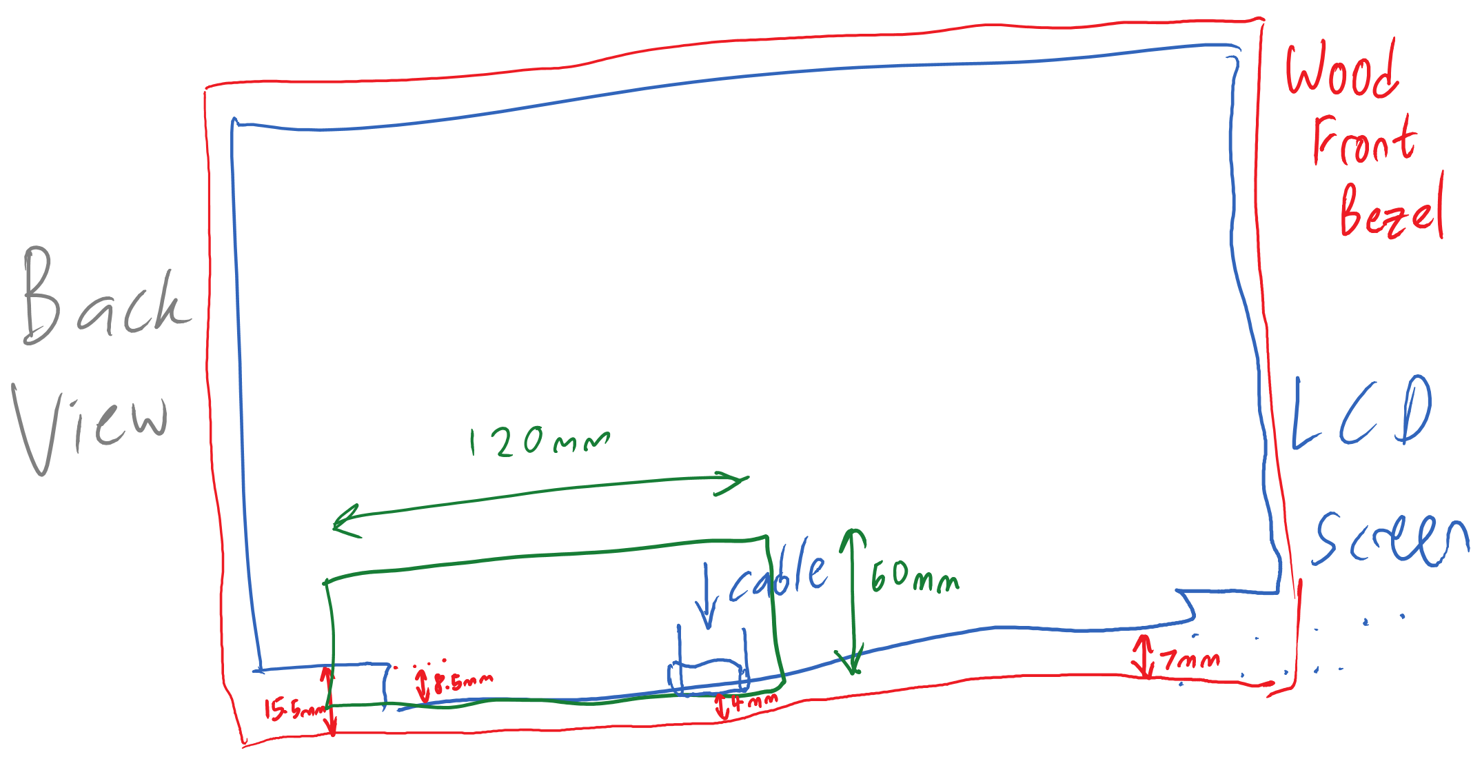
[i am drawing things! with computers!]
i'll ask a friend to lasercut the frame, because idk lasers.
and idk mechanical design either. so instead of an enclosed frame, let's make a crappy rollcage with a front bezel and a back panel. but how to hold the panel in place?
let's hold the panel with a 'lip' made from standoffs & Nylon washers:
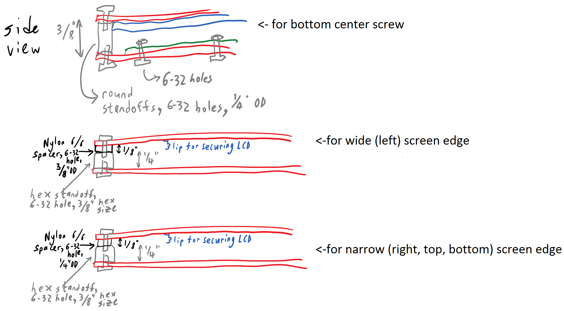
and now, a PCB!
i call it the 'L' board.
 [schematic of 'L' board]
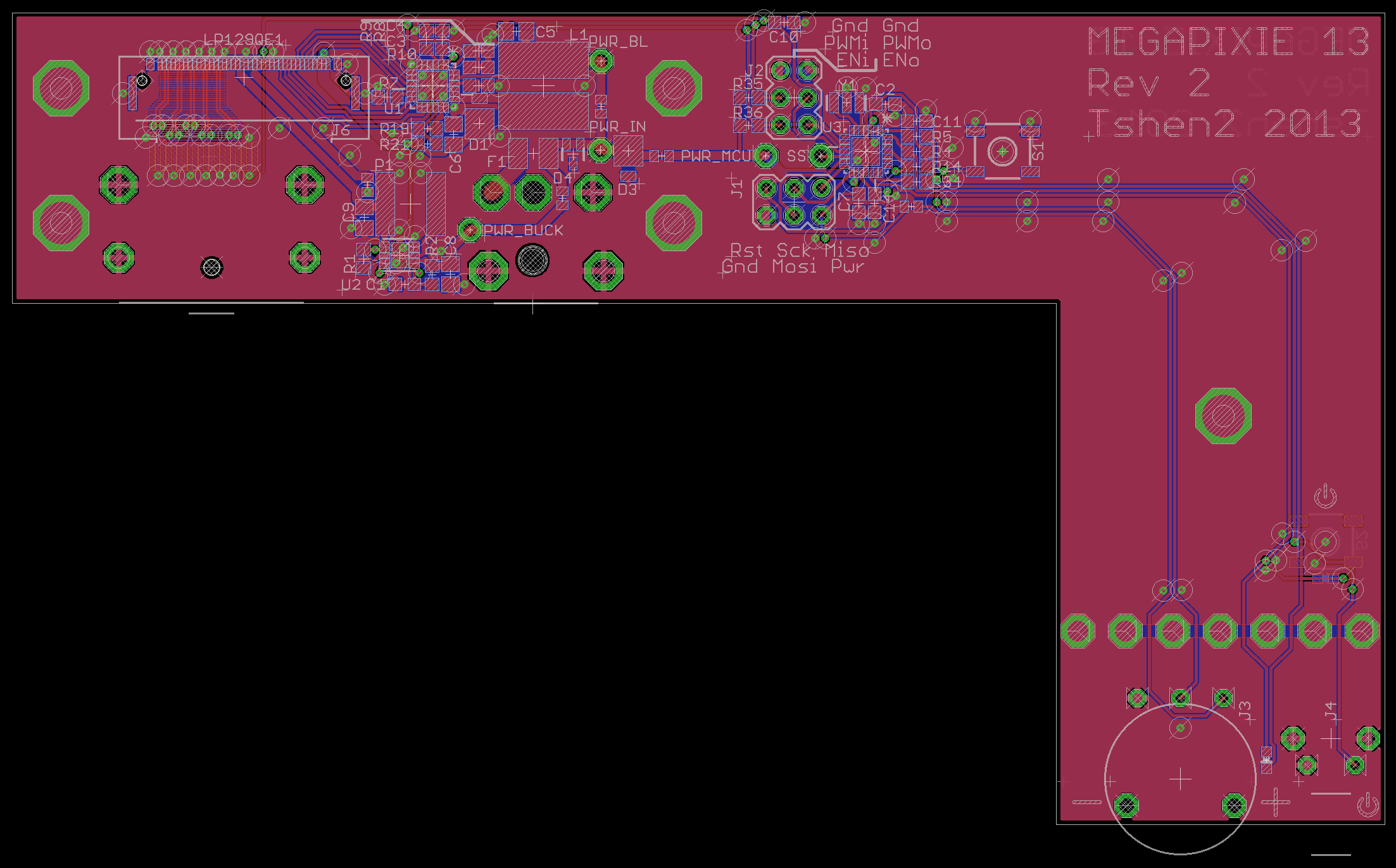
as per my war on identical rows of buttons, there are only two controls:
it's obvious, even in the dark. a dial is ideal for adjusting brightness, and doesn't feel like a button at all.
but this board is horribly flawed, because the Displayport cable and delicate LCD cable end up bumping into each other.
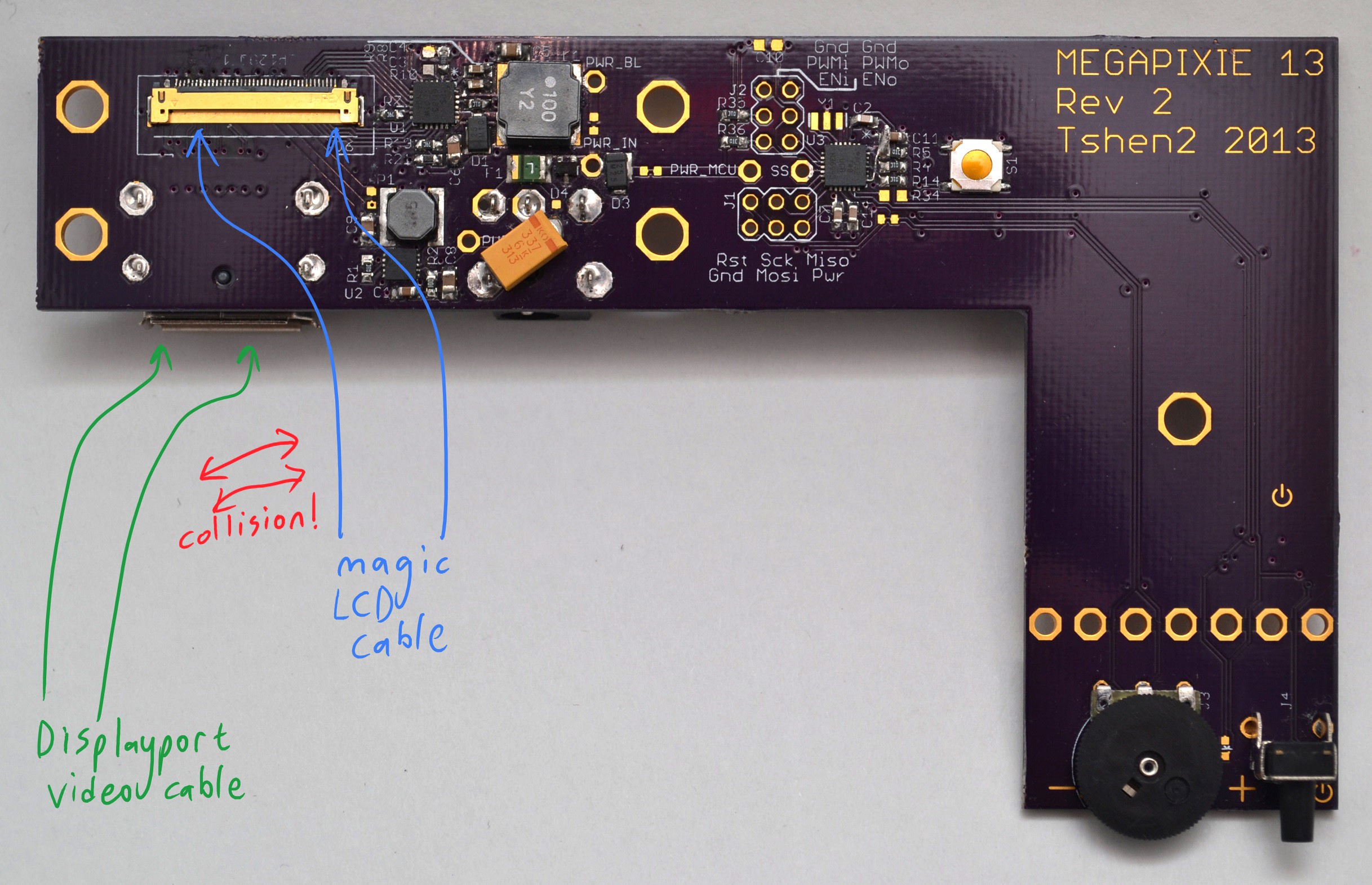
[not so good!]
why is this happening? because the 'L' board is a crude extension of my test board. i tried to keep my high-speed traces as short as possible on the test board, which created that awkward cable collision.
so i have to make a new test board, to put some distance between those cable connectors.
time for more shotgun engineering!
[boom!]
now there's a 90-degree bend between connectors to prevent cable collisions! and with this, i built the 'comma' board.

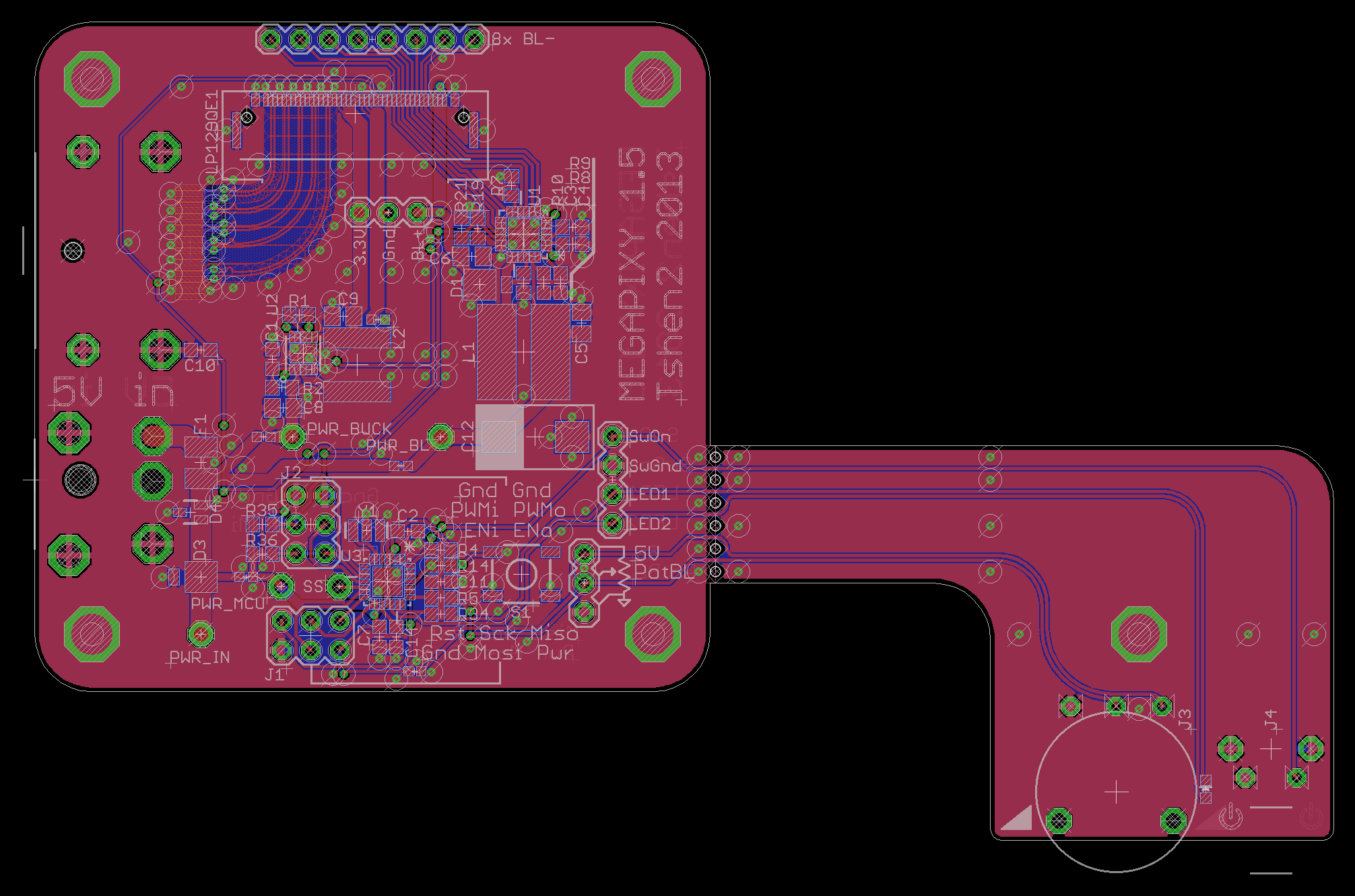
did you notice all those holes at the neck of the comma? they let you snap off the on/off button and brightness dial.
this lets you build a mega-screen with multiple LCD panels and control...
Read more »in my last update, i assembled a mediocre monitor using an AU Optronics LCD panel. it required an LCD control board to act as an HDMI-to-LVDS converter, for LVDS is the language of most LCD panels.

[old-fashioned LCD panel requiring an LVDS converter to connect to a computer.]
but LVDS is losing popularity. as our phones & tablets keep shrinking, how can anyone make room for that LVDS-converter chip? the logical solution is to build a standard ('not LVDS') video interface into the panel, to connect it directly to your graphics card.
the embedded Displayport (eDP) standard was introduced in 2008 to do exactly that. Displayport is the best video interface, LCD manufacturers can build eDP interfaces directly into their panels, and those panels no longer need an LVDS converter.
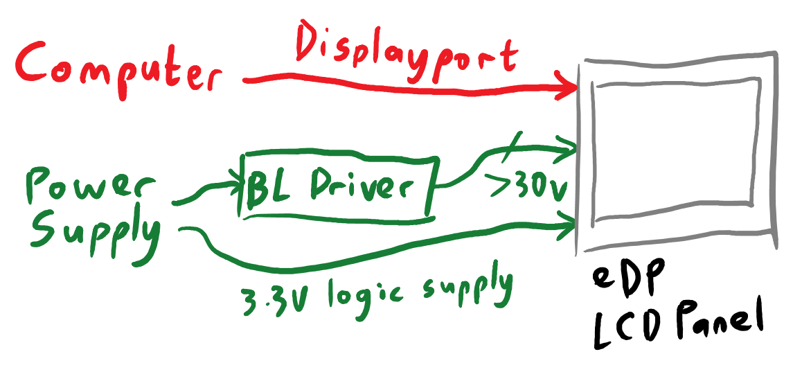
[LCD panel with embedded Displayport. the video interface connects directly to computer's graphics card.]
do note that eDP, while electrically identical to Displayport, does not use the standardized Displayport connector. every manufacturer has their own favorite connector which can vary from panel to panel. this is why all eDP hobby projects boil down to 'how do i connect these super-high-speed RF signals from my Displayport connector to this crazy LCD panel connector?'
Examples:
at this point, since all the cool kids were hacking the 9.7" Retina iPad panel, i decided to do it too. and why not? it's a great (if small) IPS panel with awesome contrast & colors & viewing angles. it's made by LG and the datasheets are everywhere.
so what is actually needed to get it working?
it would have been sensible to build the bare minimum first, and get fancy later.
but i was impulsively complicated, so i added a fancy boost-converting backlight driver IC, power-management IC and Li-ion battery into the screen, to keep it running on the go. plus an ATtiny48 to talk to everything through I2C. keeping in mind that two years ago:
but what the heck, i did it anyway. and here is the result:
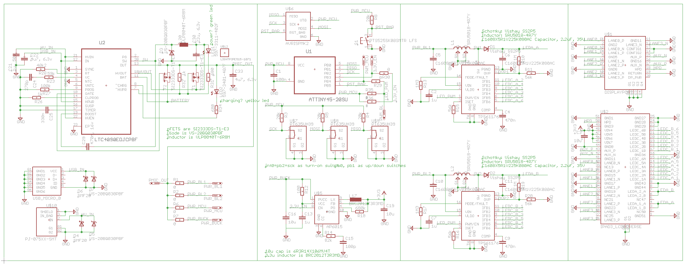
[Retina iPad interface board, attempt #1 - schematic.]
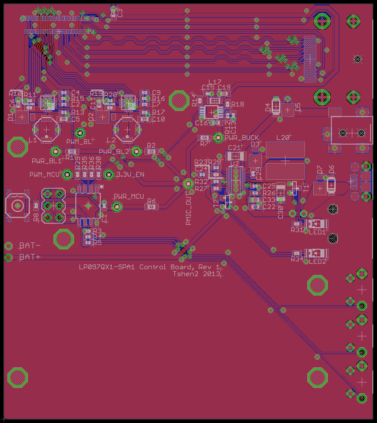
did it work? not at all. it certainly didn't work aesthetically.
i'd also used the Displayport source pinout instead of the sink pinout, which doomed my board from the start. i hadn't even realized there were different source & sink pinouts. i should have dumbed things down, and got the basics right.
instead i designed another ugly and overly-complicated board because i was clueless in 2013.
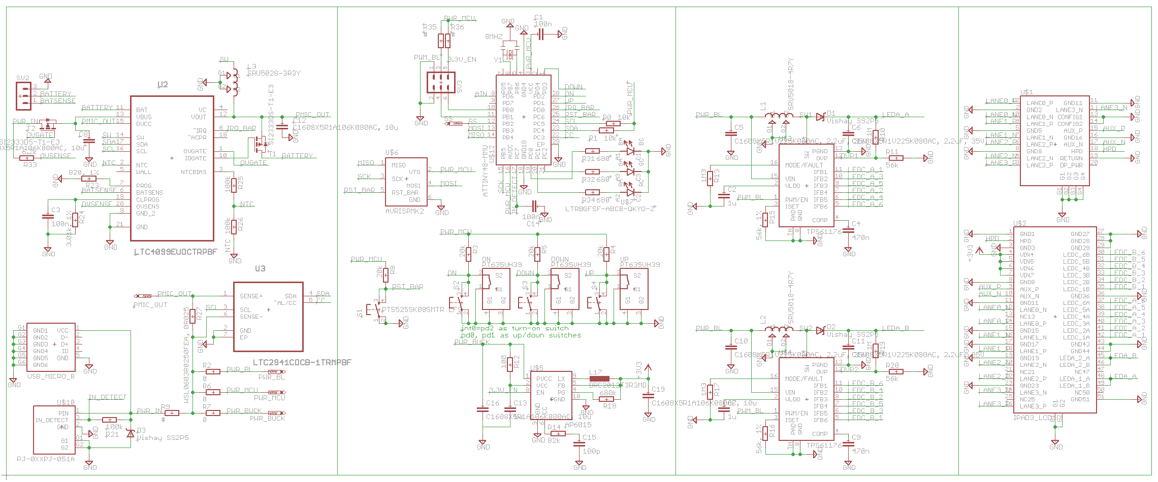
[Retina iPad interface board, attempt #2 - schematic.]
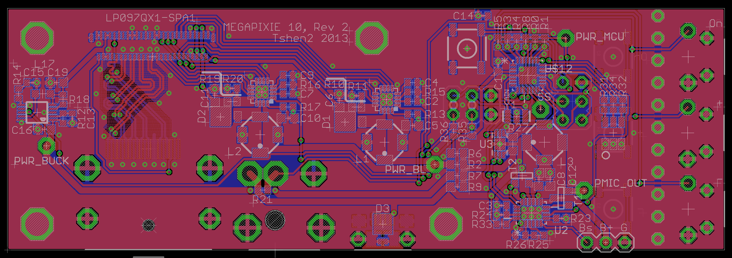
did this work? not even a tiny bit. i still had no idea how to route those high-speed Displayport traces.
this was pretty frustrating. each round of PCB-fabbing cost me a bunch of money. i was buying lots of tiny parts and painstakingly soldering them. nothing was working and i had no clue what i was doing. then i found OSHpark.
OSHpark is a PCB ordering service where...
Read more »to write about Megapixy is to write about the last 2 years. this project has tested my patience and perfectionism and pursuit of beauty as few have.
Megapixy was an adventure in sourcing parts. it was my first self-directed surface-mount PCB design, my first try at soldering QFN & DFN packages, my first attempt to route high-speed differential signals, my first non-Analog system design.
Megapixy was my first lasercut design. it birthed my Eagle-mechanical workflow and represents my highest level of electro-mechanical integration to date.
Megapixy was very, very confusing.
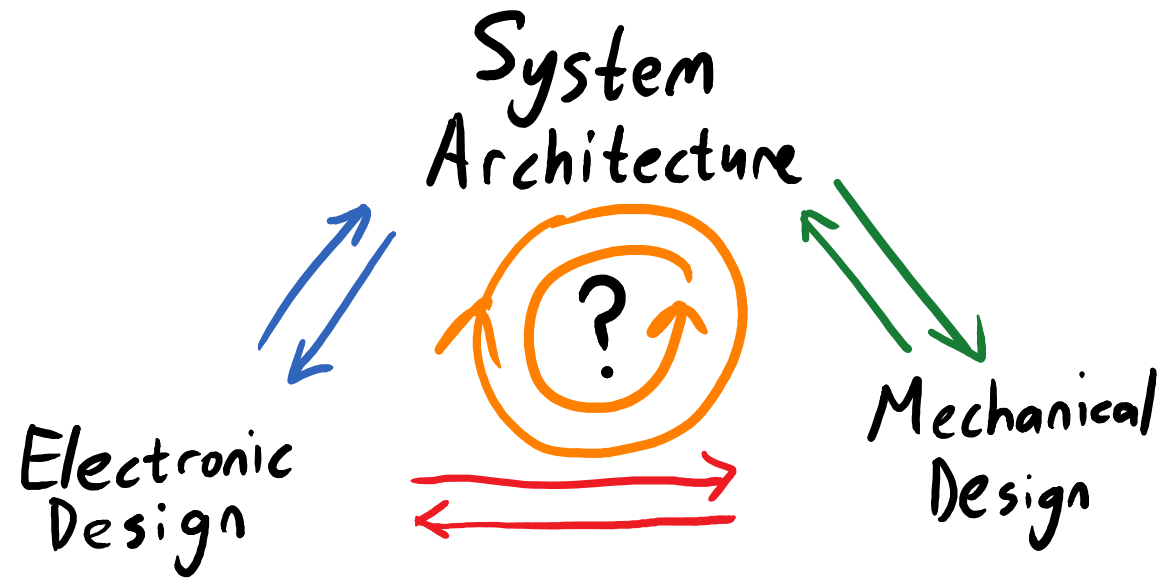
let's say you were to build a small music studio. wouldn't it be great to have a small laptop-sized screen above the MIDI keyboard, so you could see what you were doing?
it turns out that hardly anyone makes nice small screens. Lenovo makes an awful battery-powered thing called the LT1421, with terrible colors, terrible brightness & contrast, USB-input only and pixels the size of your head. there's also this other thing with equally bad contrast and colors and general DGAF-ness. this was 2013 - the Retina iPad was just a few months old, and 1080p screens were finally beginning to trickle into Windows laptops. i would settle for nothing less.
the solution, of course, was to build something. i zoomed around the internet looking for laptops with good screens, bumped into the (otherwise uninteresting) Dell L502x, and identified its LCD panel as an AU Optronics B156HW1. a quick trip to eBay nabbed that and an HDMI-compatible control board to drive the panel, and i was in business.
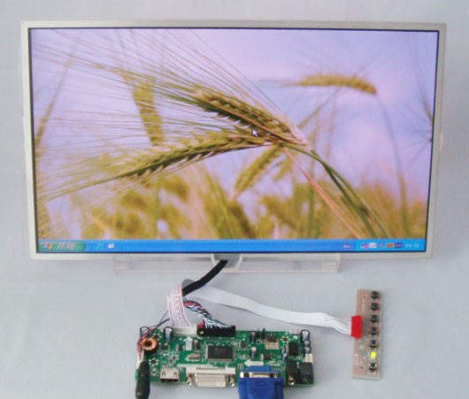
[this is really the best picture i could find.]
you need that control board because the LCD panel communicates through LVDS, and your computer does not. the control board also contains the backlight driver to run the backlight LEDs inside the panel.

it works as well as you'd expect from a generic off-the-shelf solution. it turns on and it's definitely a screen, but you won't feel any joy in it.
a screen is only useful in front of your face, so i slapped together a chassis. having hardly any tools in 2013, i asked a frame shop to frame the LCD panel like a painting, and built the rest of the chassis to screw into the rear of the frame.
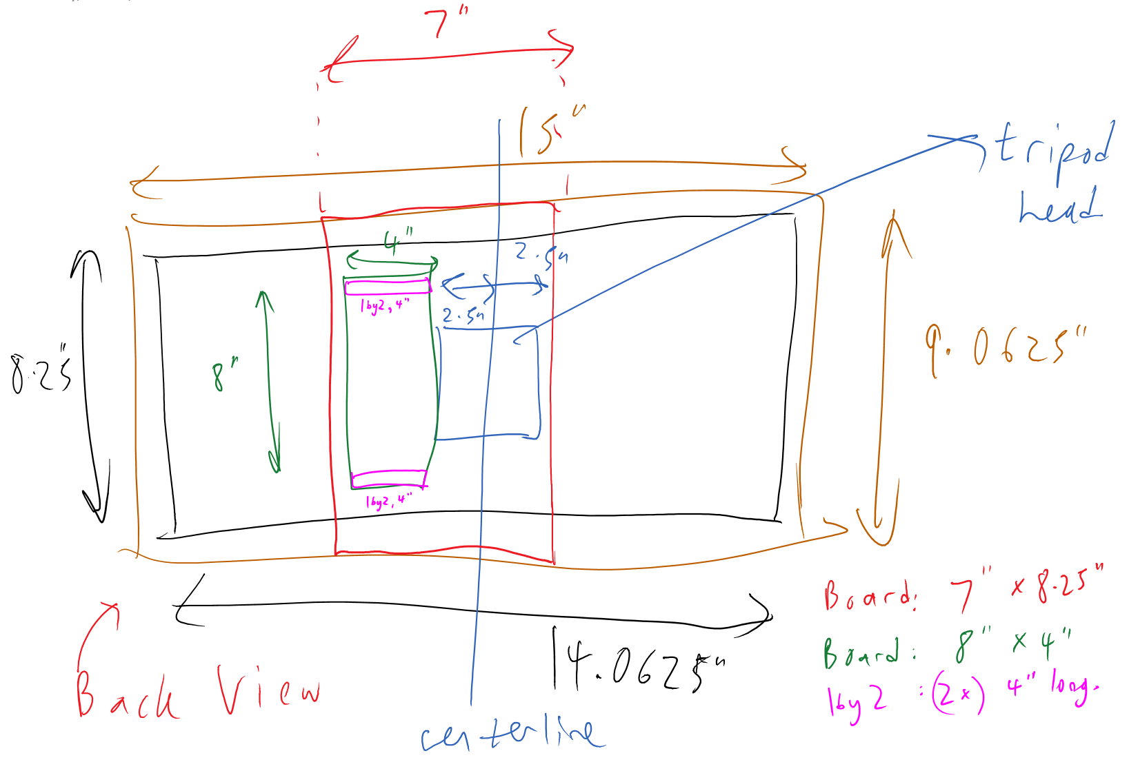
[Shen's handwriting, circa 2013.]
after much drilling, sawing, gluing & screwing:
[and those pixels are still pretty pixelly.]
[the back is.. not so good.]
i used a 1/4-20 T-nut to mount the chassis to a tripod, as i often do. i'm not thrilled, but it works. what should be better?
no seriously, why do all monitor controls suck?
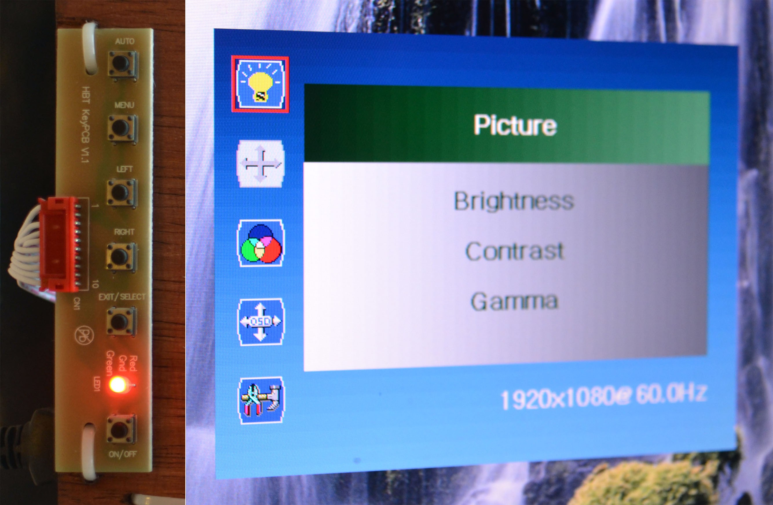
[identical row of control buttons (left), on-screen settings (right).]
even the most crazy-expensive professional LCD monitors use a row of identical, nasty-clicky buttons. you have to look at them since they all feel the same, but you also have to look at the screen to see your on-screen settings. so your eyes will dash back and forth, between buttons and screen, until the controls time-out and the on-screen settings vanish. and then you'll have to start over.
*cue much wailing & gnashing of teeth*
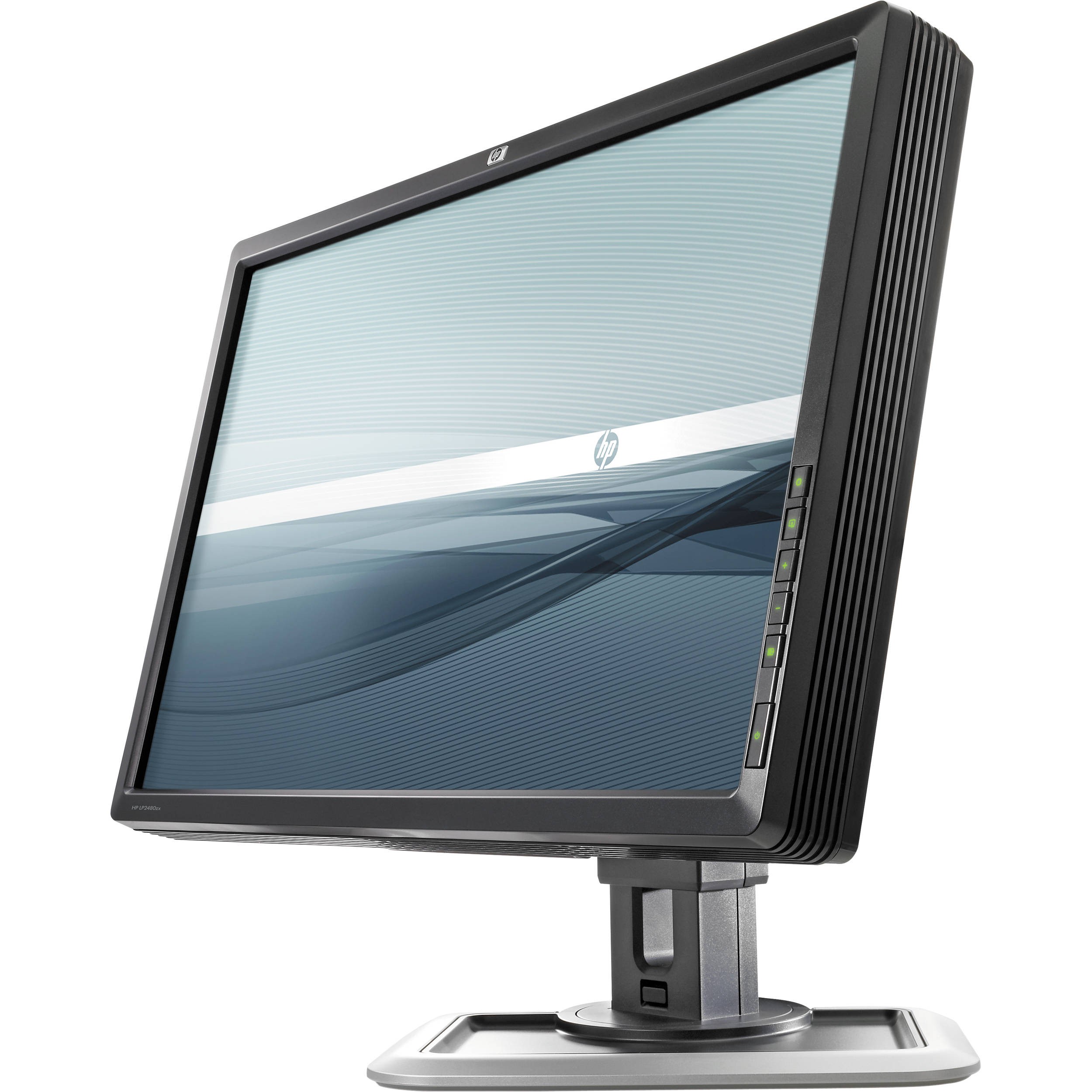
isn't this crazy? doesn't this drive you nuts? am i just weird?
i mean, your computer's operating system already has color, brightness and gamma controls. the advice of professionals is to keep your screen unadjusted (except for brightness) and do all adjustments in software. why do our screens need anything beyond a power button and brightness control?
and how can i make a better screen without relying on someone else's crappy control board?
then someone clued me in on a very interesting Hack-A-Day article, and i started thinking...
Read more »
Create an account to leave a comment. Already have an account? Log In.
Awesome project!
What did you pay for the cable and who sold it to you?
hello!
i paid way too much for the first few cables (~$15 each), although of course all things scale with quantity..
i think it was these people:
http://www.alibaba.com/product-detail/I-PEX-Mini-Coaxial-LVDS-Cable_757849409.html
i have a lot of spare cables - if you want to try this project, i should just sell my spare cables. email me ( shen@latentlaboratories.com ) if you want one.
The project sounds very interesting and I think that the guys over at the bongofish.co.uk forums would be very interested for their DIY-Cintiqs (Wacom graphic tablets).
I don't have any use for it (for my desktop I would like to get a similar screen in the range of about 22" but 13" is a bit small...).
I will link them to this project. Let's see if you get some cable requests from them :P
holy snap... $15 for a custom cable of that variety is *well* within reason... 'twas a time I recall refusing to order a simple custom-length 7in IDC cable (*IDC* fergoshsake) for something like $50. Bought a crimper, a ton of IDC connectors, and a lot of extra cable for the same price, instead. That ain't even an option with cables of this variety.
Awesome project, but i just cant help myself from pointing out 'retina' is a dumb marketing term, and there are MUCH nicer screens out there.
That said, ill say it again, awesome project! :) love the idea, and the end result.
hi suicidal.banana!
i agree with you, but the term 'hi-DPI' hasn't gotten much traction :-/
durrrr Apple and their name-brand recognition.
Become a member to follow this project and never miss any updates
 Dylan Brophy
 GOAT INDUSTRIES
 Dominic Emond-Belanger
 Julien
great job overall on this project, now I want to build a copy of your design as a companion for my thinkpad yoga, rock on!