How it works?
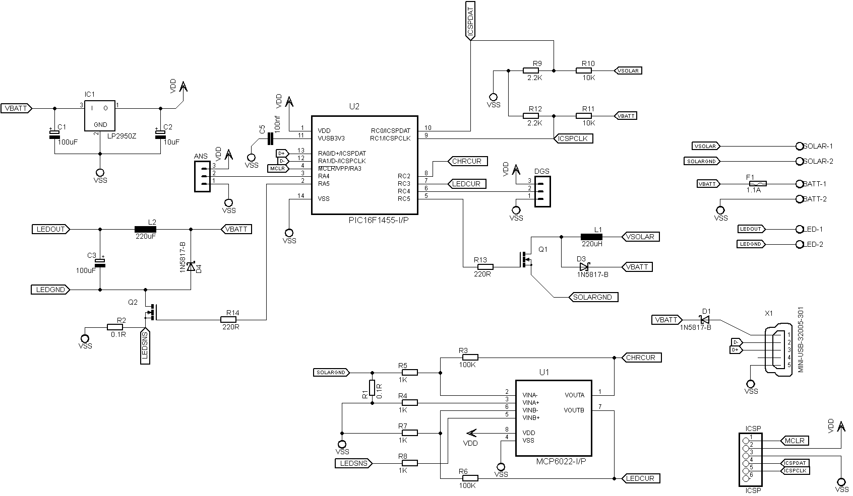
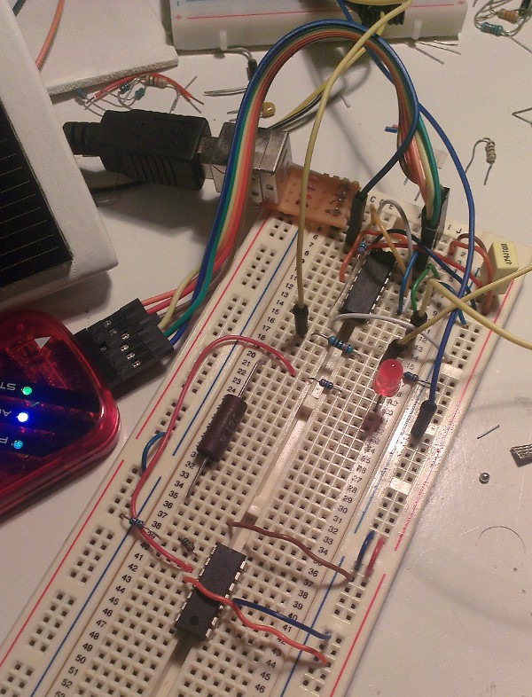
Since I started this project I have made dozens of experiments with a variety of sensors, charging and switching methods, types of batteries, solar panels, inductors, mosfets etc... And the device had usb capabilities from the beginning so I have the opportunity to compare complexity vs. efficiency during these experiments. You can find most of these experiments and design decisions in the project logs. Below are the major building blocks:
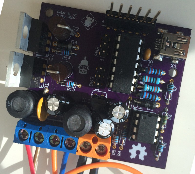
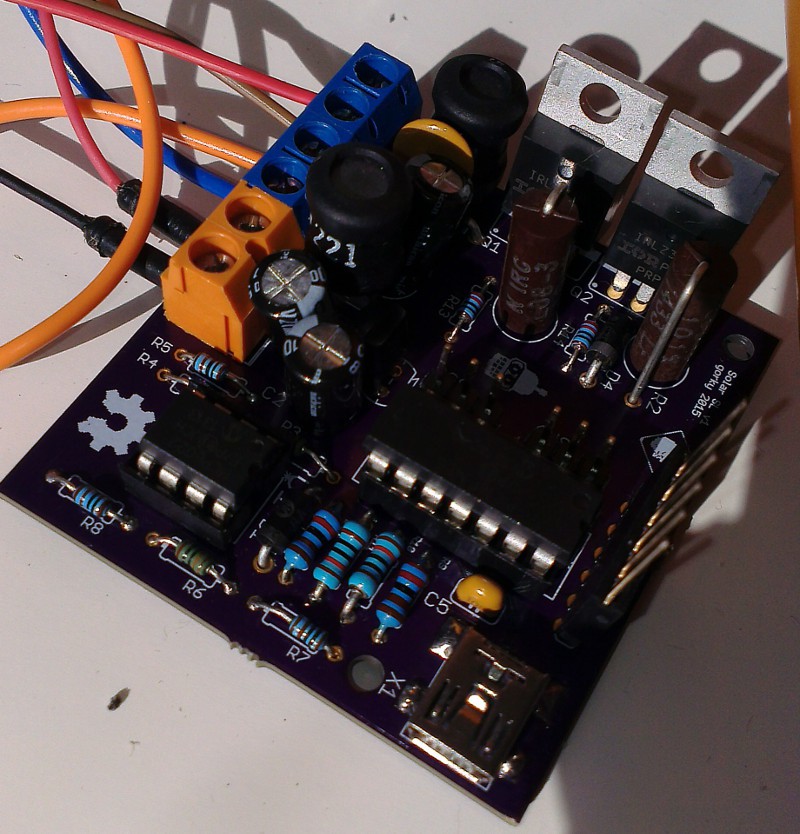
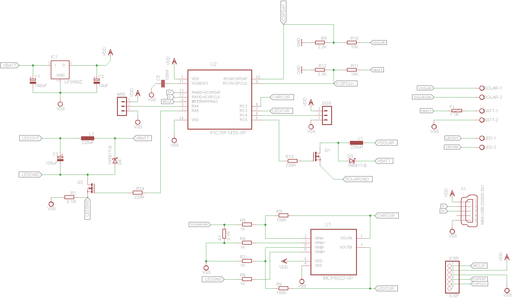
- MCU and switches: Charger, led supply, sensors are all controlled by PIC 16f1455. I chose this one as It's low cost and has a rich set of features such as internal usb module, temperature sensor plus plenty of ports. NDS331N
mosfets are used for chargers and led drivers switching supplies.
- Battery: Main power storage for the device will be 6v SLA battery by default. However as charging algorithm is completely configurable in theory any battery with higher voltage than panel's max. voltage can be used.
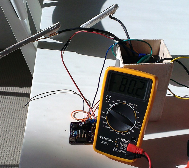
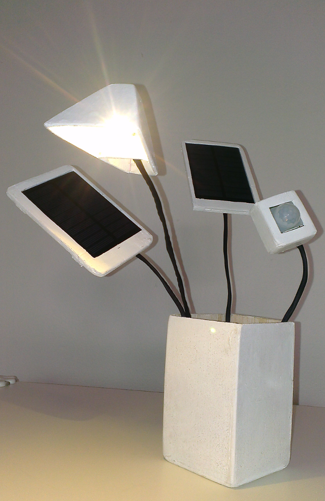
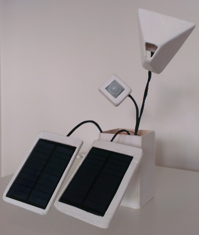
- Solar panels: Main power source for the device will be 2x 6v 1W solar cells by default. However as above any panel setup can be used as long as its max voltage is lower than battery voltage and maximum power doesn't exceed 5W.
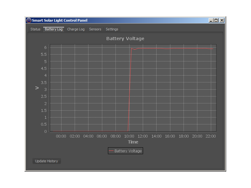
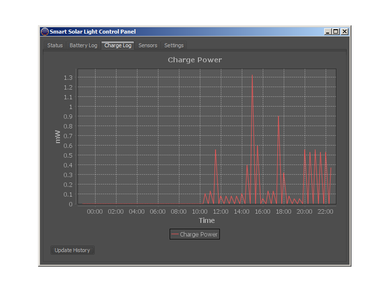
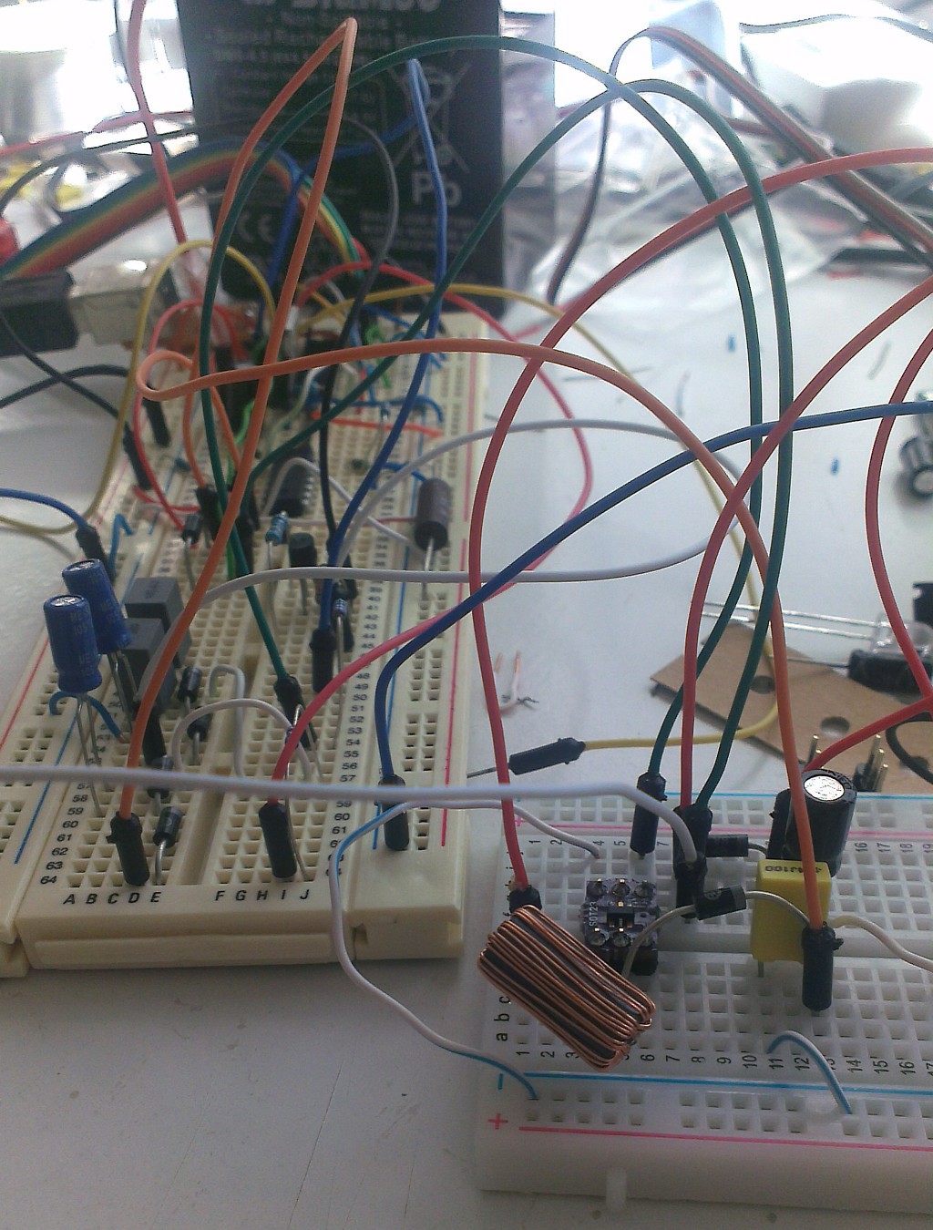
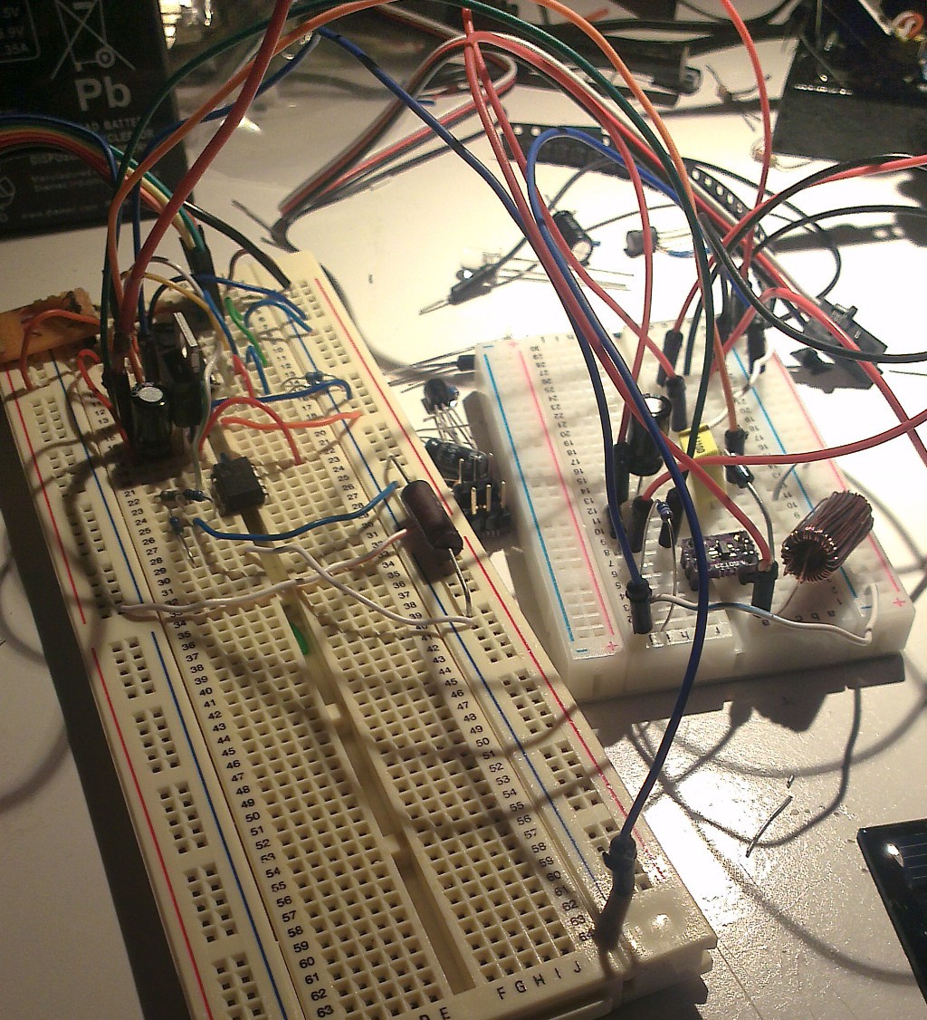
- Charging module: A boost converter controlled by PIC microcontroller with constant current, constant voltage, temperature compensation and battery health check features.
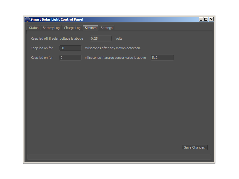
- Sensors: Device will detect human presence and light conditions and decide to turn on, off or sleep. For now solar panel voltage will be used to detect ambient light. A motion sensor module will also be used by default. Another optional analog sensor will be used (such as a sound or distance sensor) to close gaps of the motion sensor.
- LED and LED Driver: A 3w warm white led powered by a constant current mode buck converter controlled by the micro.
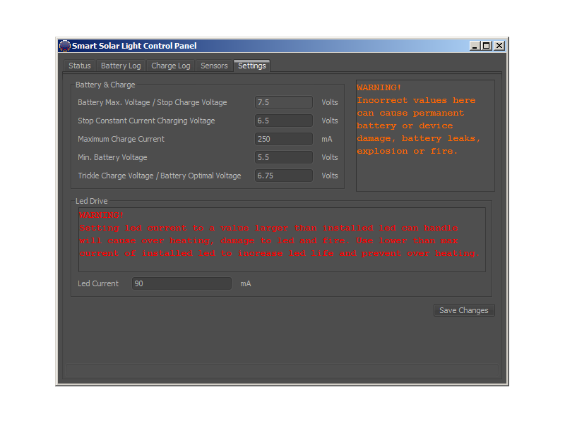
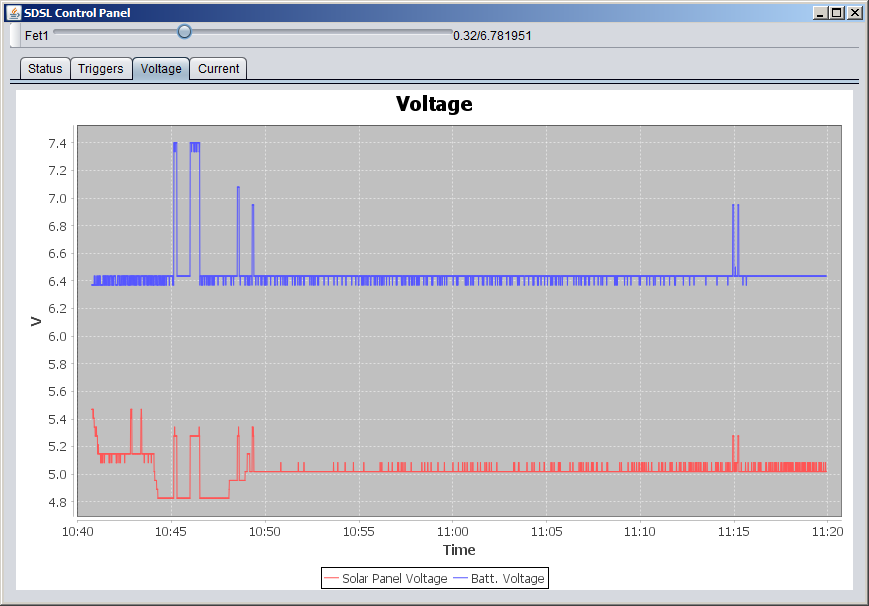
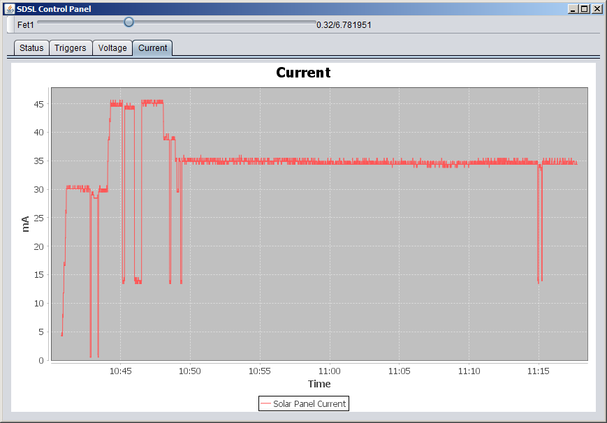
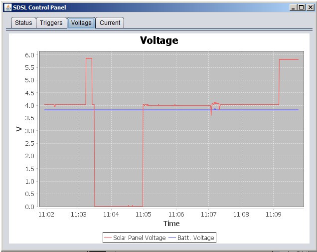
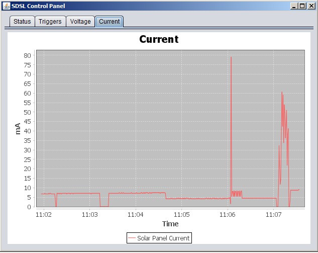
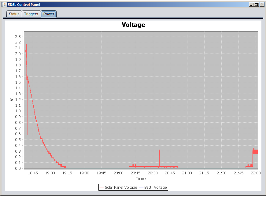
- Configuration, debug : Currently device is a custom HID device that can communicate over USB to a piece of java software plotting a couple of values. During the first phase of the project I will improve this software to setup and modify charging algorithm, power saving features such as sensor thresholds and timings and power usage features such as adjusting output current. Having said that I am planning to replace all usb communication with wifi. Starting with usb was a bit easier for me but with modules like esp8266 and usb issues with open source wifi is obviously a better way to go for open source projects.
Goals
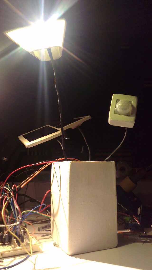
The end product will be something similar to a conventional desk lamp. Goals below will be success criteria for the project.
- Design : Final product should have a solid, sleek look and it should be very easy to configure and start using. While in use it should require as little maintenance as possible. (Such as changing batteries, cleaning up solar panels)
- Functionality : Amount of light produced should compete a conventional light bulb powered by the grid or at least provide a functional replacement for a small desk lamp.
- Cost : While not being the primary goal, price tag on the final product plus batteries shouldn't scare first buyers.
- Simplicity: Number of components and complexity of hardware and software should be as simple as possible enabling more people to diy this project easily.
Why Does It Matter?
I am living in a leased unit where I can't install a full blown proper solar system. Assuming that is the case for a majority of people especially living in heavily populated cities where power consumption is highest, a practical, efficient, budget solar product that can take out one appliance at a time off the grid without any harm or loss in function will provide people the opportunity to try it out within their budgets.
If this project or any similar product can successfully make it into the common household then it might start a reaction leading to more industry and scientific attention, more investment, better solar panels, better batteries etc. and most importantly better ideas. Imagine what the light bulb did to electricity but without...
 Gorky
Gorky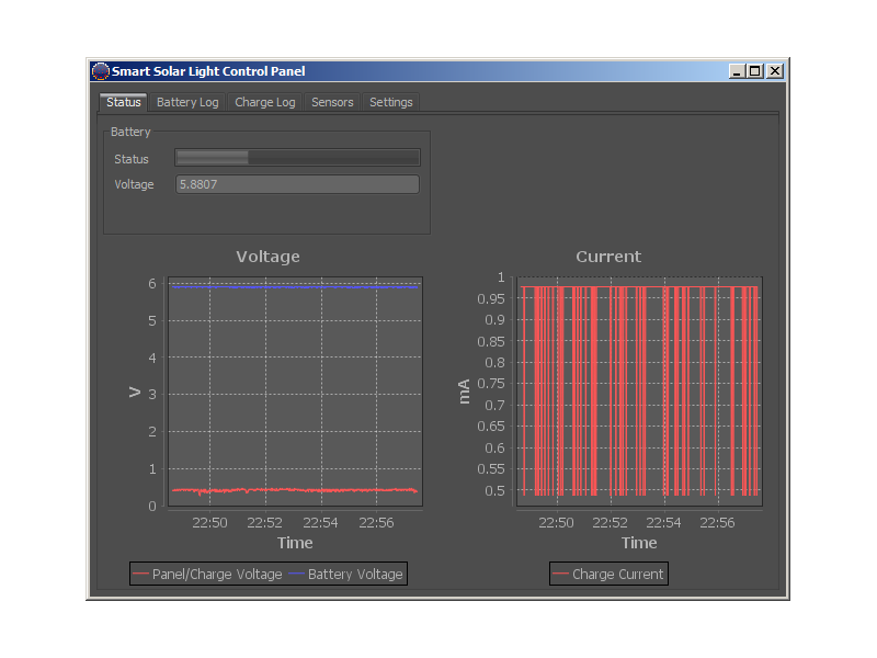



 DrYerzinia
 Alex Klimaj
 Said Alvarado Marin
simple "stupid"
"Wham Bam" regulator ( UVLO ) - modify a buck
http://www.fieldlines.com/index.php?topic=146685.0
"They have a control pin that is either on or off. The pulse duty never
changes, just the number of pulses. It is much more efficient to
design a transformer for a fixed duty cycle than for PWM. With 120,000
or more pulses per second, an operation with 50 pulses on and 100
pulses off doesn't look any different to the end user than PWM"
-------------------------
The circuit simply fakes the input sense pin into believing the output of
the regulator is too high thus shutting it down. Input and output work
in perfect harmony.
http://www.fieldlines.com/index.php/topic,144628.msg977808.html#msg977808