johnowhitaker
-
Sound output looking noisy
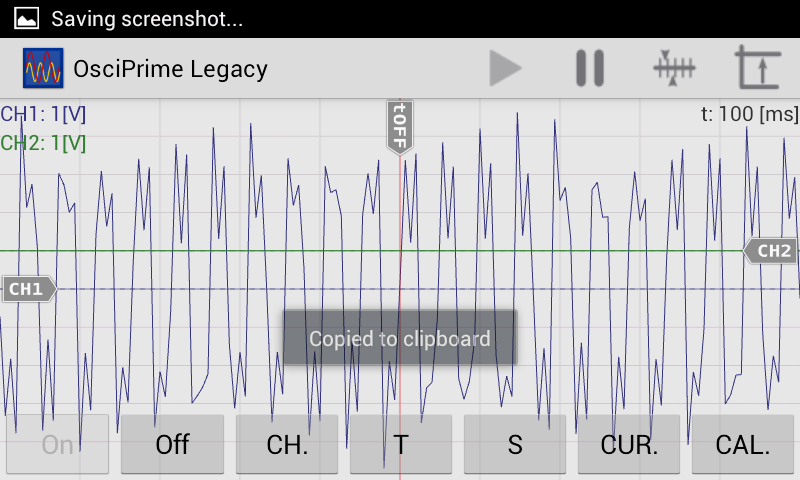
07/02/2015 at 09:27 • 0 commentsI'm using a timer to toggle a pin on the ATtiny85. Was hoping for a nice square wave, but looks a little noisy:
![]() Should still do the job.
Should still do the job.NB this could also be because of my utterly hacky 'scope (https://hackaday.io/project/6511-cell-phone-oscilloscope)
-
ATtiny test code working, trinket has arrived!
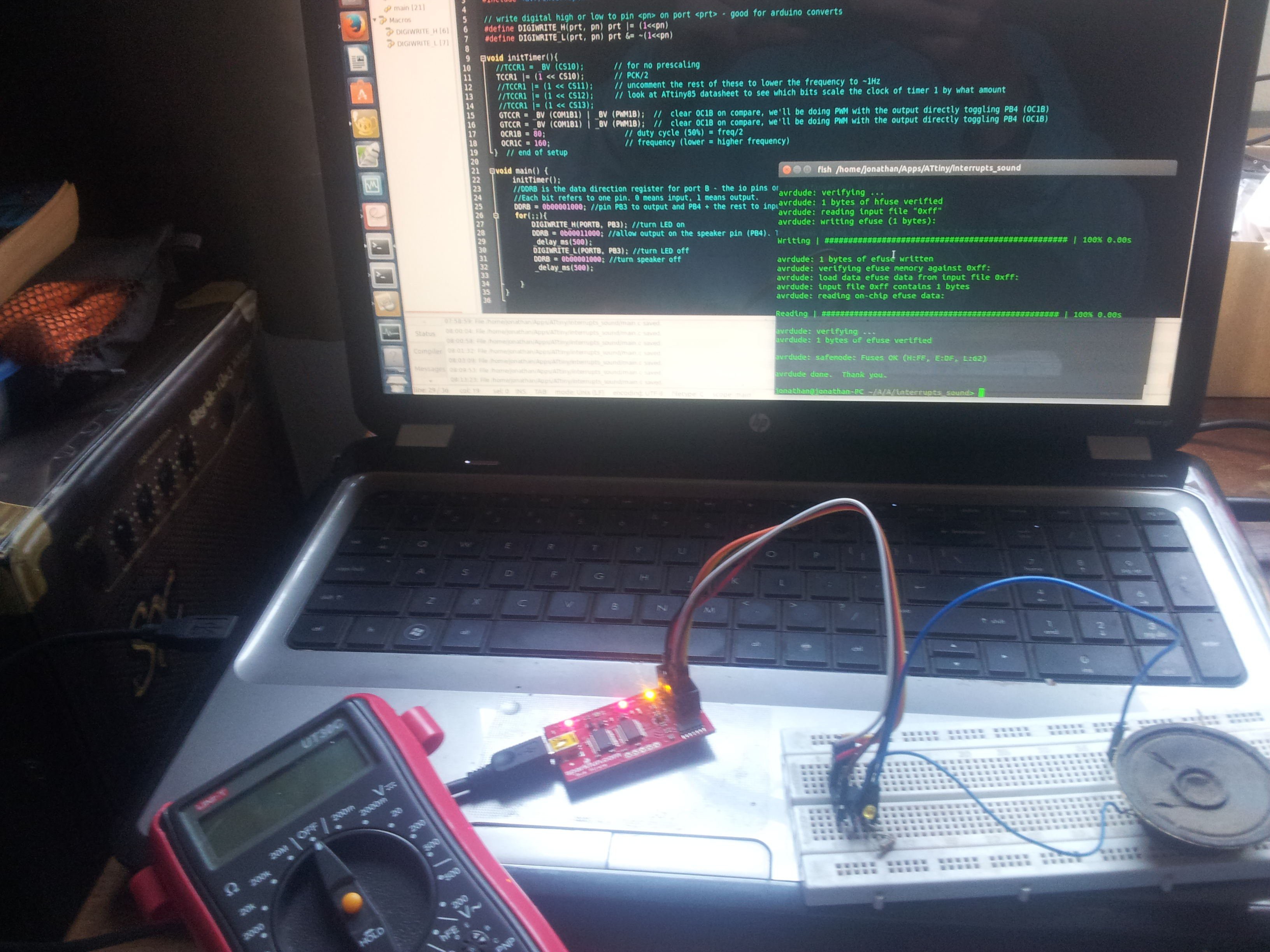
06/18/2015 at 06:58 • 0 commentsI finally got the ATtiny85 code behaving as I want. It simultaneously sends out an ultrasound beep and flashes an LED. I can now start writing code to detect these and estimate distance. The code uses the internal timer1 to do PWM, generating the required frequency without using up CPU resources. This is vital as it will need to do other things. I also have interrupt code for when a button is pressed and some other fluff, but for now this is all I need to test everything. Here is the code:
#include <avr/io.h>
#include <util/delay.h>
#include <avr/interrupt.h>


// write digital high or low to pin <pn> on port <prt> - good for arduino converts
#define DIGIWRITE_H(prt, pn) prt |= (1<<pn)
#define DIGIWRITE_L(prt, pn) prt &= ~(1<<pn)


void initTimer(){
  //TCCR1 = _BV (CS10);       // for no prescaling
  TCCR1 |= (1 << CS10);       // PCK/2
  //TCCR1 |= (1 << CS11);      // uncomment the rest of these to lower the frequency to ~1Hz
  //TCCR1 |= (1 << CS12);      // look at ATtiny85 datasheet to see which bits scale the clock of timer 1 by what amount
  //TCCR1 |= (1 << CS13);
  GTCCR = _BV (COM1B1) | _BV (PWM1B);  //  clear OC1B on compare, we'll be doing PWM with the output directly toggling PB4 (OC1B)
  GTCCR = _BV (COM1B1) | _BV (PWM1B);  //  clear OC1B on compare, we'll be doing PWM with the output directly toggling PB4 (OC1B)
  OCR1B = 80;                   // duty cycle (50%) = freq/2
  OCR1C = 160;                  // frequency (lower = higher frequency)
}  // end of setup


void main() {
    initTimer();
    //DDRB is the data direction register for port B - the io pins on the ATtiny85 are all in port B.
    //Each bit refers to one pin. 0 means input, 1 means output.
    DDRB = 0b00001000; //pin PB3 to output and PB4 + the rest to input for now(pins 2 and 3 on DIP ATtiny85)
    for(;;){
        DIGIWRITE_H(PORTB, PB3); //turn LED on
        DDRB = 0b00011000; //allow output on the speaker pin (PB4). This saves having to stop and restart the timer each time.
        _delay_ms(500);
        DIGIWRITE_L(PORTB, PB3); //turn LED off
        DDRB = 0b00001000; //turn speaker off
        _delay_ms(500);

    }
}
I program the chip with a bus pirate as detailed in a previous log, and I can then easily test it by turning on power from the bus pirate from a serial console. The uses of that tool continue to amaze :)
![]()
Next in the TODO list is to hook up a mic + preamp to the teensy and see if we can detect sound...
-
Advice requested: Phone or Teensy
05/08/2015 at 19:42 • 0 commentsThe main base station (Master) needs to be able to time the delay between an IR flash and the arrival of an ultrasound pulse (my best idea for estimating distance). I was thinking of offloading some of the work to a phone by using the headphone jack as IO. However, the post on teensies made me wonder if detecting a 25kHz tome would be doable fast enough on a low cost arm processor. This would make the project more self-contained and probably cheaper... Anyone have thoughts on this, or experience detecting specific frequencies with a micro?
-
Begging for PCBs
04/27/2015 at 06:31 • 0 comments![]()
In this log I'll outline the PCB work I'll need to move this project along, as suggested in this HAD post, although the dog makes my case fairly eloquently already :)
There will be two separate boards for this projects, which I'm going to call the master and slave. I'm not sure how I'll design the master board yet. It may be an expensive but easy arduino+GPS+SD Card stack, a nice custom board or (the option I'm leaning toward for now) AA simpler board that plugs into a phones earphone socket and offloads the hard work of logging, GPS, UI to the phone. I think this last idea would be best as it will keep costs very low and allow me to get started without waiting 2 months for a GPS breakout board. If I go with this option, I'll just need a fairly small PCB with a few IR LEDs and IR recievers (like those in DVD players, which have some extra circuitry built in to make life easy), a micro (probably an ATtiny85 just to be consistent) and a battery connector.
The 'slaves' will be easier. Each one will be an ATtiny85, a boost converter to power from a AA battery, an IR LED/reciever pair, an electret microphone with a preamp (1 transistor, some resistors), an RGB LED for status info, a push button or two for input (may need a shift register if I go with two buttons and an RGB LED, but I'll try to get away with just the pins available) and a battery holder.
Since the whole goal of this project is to keep everything small, cheap and robust, some professionally made PCBs will be a much better fit than my usual messy protoboard mashups, and if I ever plan on selling these having some nice purple prototypes would be useful ;)
-
ATtinys ready to go
04/26/2015 at 16:03 • 0 commentsI have my tool-chain all set up. Tested it today by uploading the obligatory LED blinking program.
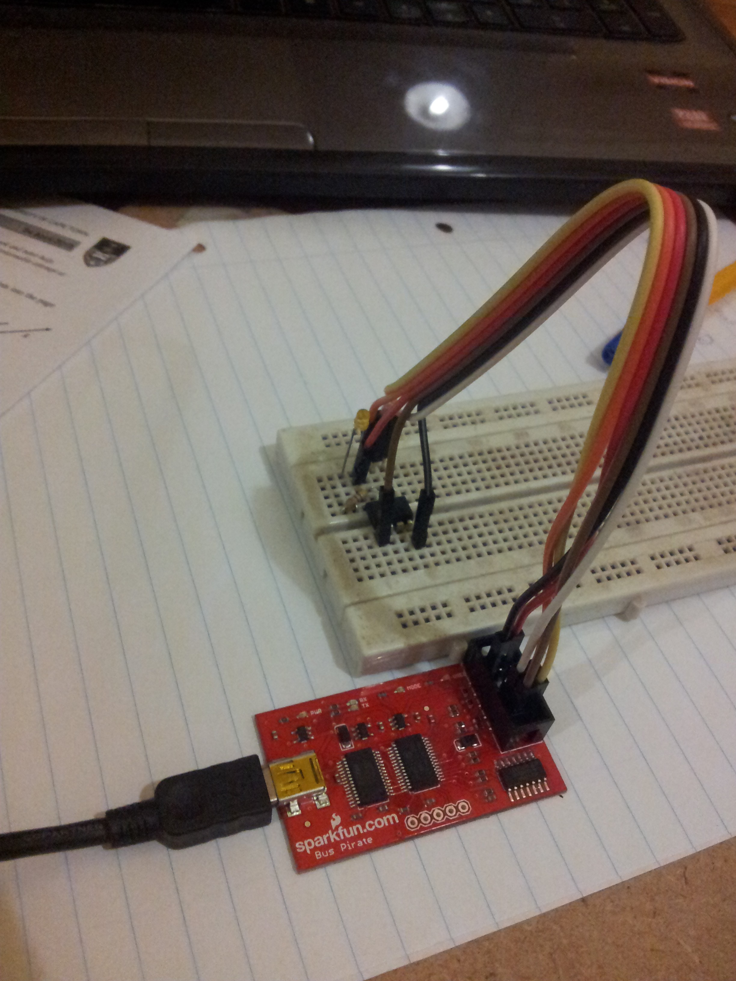
The code will be written in C, compiled with gcc-avr and uploaded with a bus pirate (my favourite tool of late) using avrdude -p attiny85 -c buspirate -P /dev/ttyUSB0.
![]()
Using the bus pirate as an AVR programmer is wonderful - no external components or power needed. I just connect +3.3V and GND to +V and GND on the 'tiny, wire up MOSI and MISO, CLK goes to SCK on the 'tiny and CS goes to RESET (pin 1 of the ATtiny85). Here is the makefile I use:
DEVICE     = attiny85
CLOCK      = 1000000
PROGRAMMER = -c buspirate -P /dev/ttyUSB0
OBJECTS    = main.o
FUSES      = -U lfuse:w:0x62:m -U hfuse:w:0xdf:m -U efuse:w:0xff:m
# generated by http://www.engbedded.com/fusecalc/

AVRDUDE = avrdude $(PROGRAMMER) -p $(DEVICE)
COMPILE = avr-gcc -Wall -Os -DF_CPU=$(CLOCK) -mmcu=$(DEVICE)

all:	main.hex

.c.o:
	$(COMPILE) -c $< -o $@

.S.o:
	$(COMPILE) -x assembler-with-cpp -c $< -o $@

.c.s:
	$(COMPILE) -S $< -o $@

flash:	all
	$(AVRDUDE) -U flash:w:main.hex:i

fuse:
	$(AVRDUDE) $(FUSES)

install: flash fuse

load: all
	bootloadHID main.hex

clean:
	rm -f main.hex main.elf $(OBJECTS)

main.elf: $(OBJECTS)
	$(COMPILE) -o main.elf $(OBJECTS)

main.hex: main.elf
	rm -f main.hex
	avr-objcopy -j .text -j .data -O ihex main.elf main.hex

disasm:	main.elf
	avr-objdump -d main.elf

cpp:
	$(COMPILE) -E main.c
Nice to have everything ready, so now I can get down to prototyping. I also plan on whipping up a PCB during my next Altium lecture (uni student, so free access) although I am tempted to go with Kicad. The only reason I'm considering Altium is that this project will probably be simple enough for others to reproduce just by looking at the schematic, and I need the practice...
EZeeSample
Shelved this one to work on other things - kept for sentimental reasons
 Should still do the job.