Radu Motisan
-
The dust sensor
07/31/2015 at 11:01 • 1 commentIf the space on the already crowded PCB allows it, the uRADMonitor-D will incorporate a dust sensor as well. I did my homework and the GP2Y10 sensors are ready to be used.
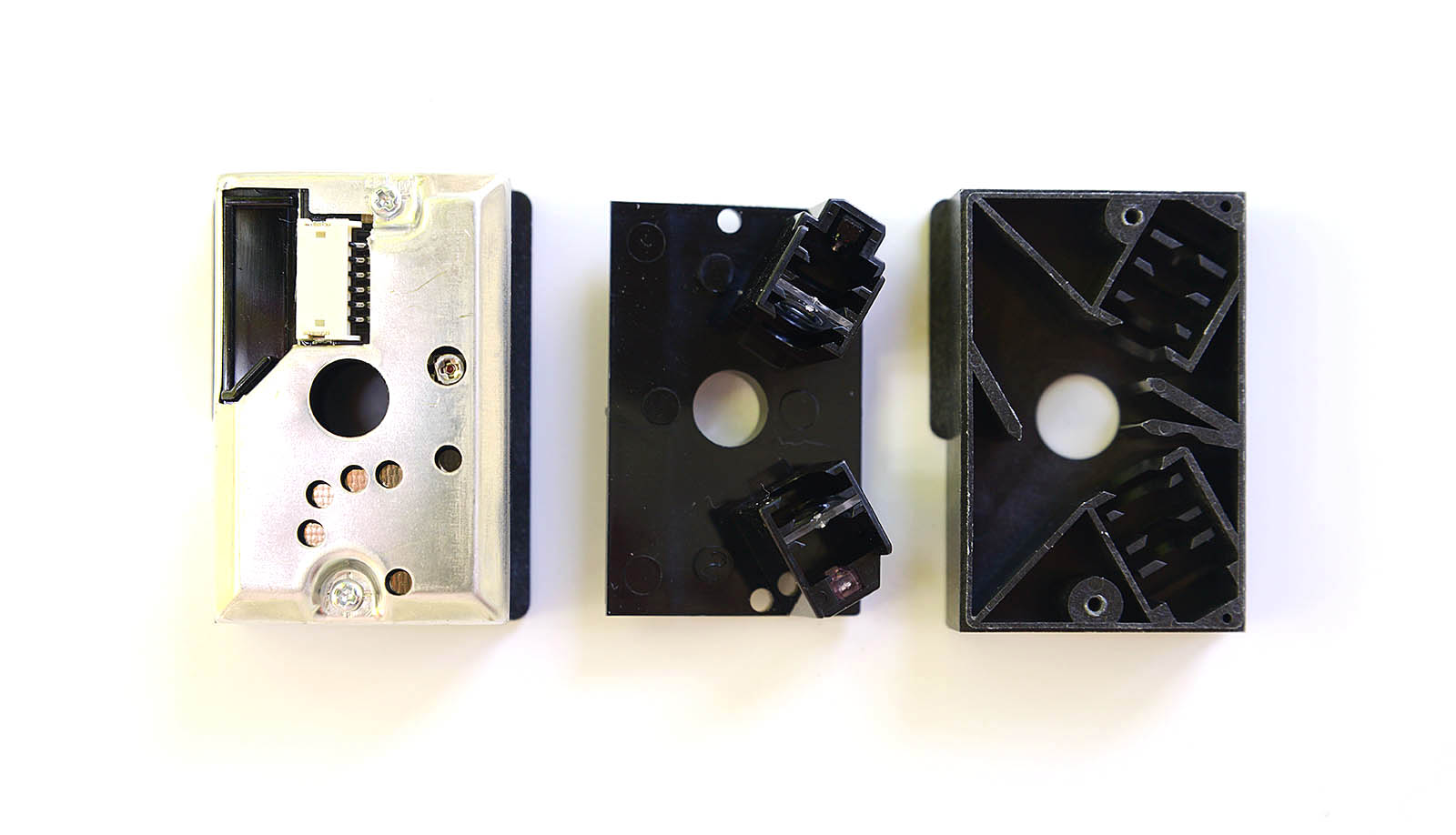
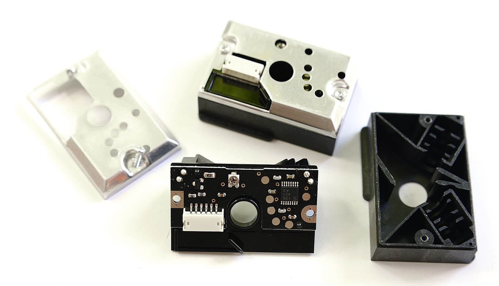
Featuring an infrared LED and, a receiving phototransistor and two lenses, this device can detect dust in air using the reflected infrared light, including very fine smoke particles. The output data patten can also be implied in smart algorithms to distinguish various types of particles. In this article I'm going to show how to connect the Sharp GP2Y1010AU0F to an AVR Microcontroller (Atmega128), how to read the output and how to convert the readings to meaningful values expressed in mg/m³. All this while using only 3.3V as input voltage.
Connecting the sensor
![GP2Y1010AU0F_2]()
![GP2Y1010AU0F_3]()
The connector has 6 pins, and a matching cable is included with the sensor. The colors are standard on all of the sensors I've seen (white, blue, green, yellow, black, red):
![GP2Y1010AU0F_1]()
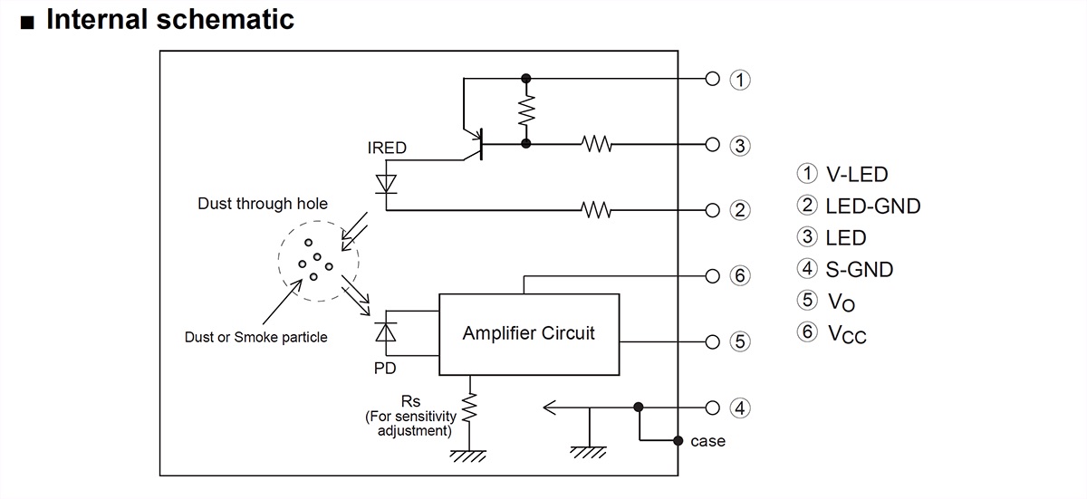
The datasheet presents the following diagram for connecting the sensor, where PIN1 is the white wire in our case:![GP2Y1010AU0F_diagram_2]()
![GP2Y1010AU0F_diagram_1]()
The 6 pins exposed by GP2Y1010AU0F, must be connected as follows:
White pin 1 (V-LED) => connected through a 150ohm resistor to the Vcc (3.3V)
Blue pin 2 (LED-GND) => GND
Green pin 3 (LED) => atmega128 I/O port
Yellow pin 4 (S-GND) => GND
Black pin 5 (Vo) => atmega128 ADC port
Red pin 6 (Vcc) => Vcc (3.3V)
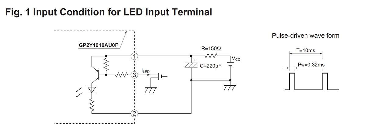
The datasheet indicates using a 150Ohm resistor between pin 1 (white, V-LED) and Vcc (3.3V), and a 220uF capacitor . These are optional, since the device will work fine and with the same output when PIN 1 is connected directly to VCC (without resistor), and the capacitor is omitted. However the datasheet also indicates that:In circuit designing, make allowance for the degradation of the light emitting diode output that results from long continuous operation. (50% degradation/5 years)
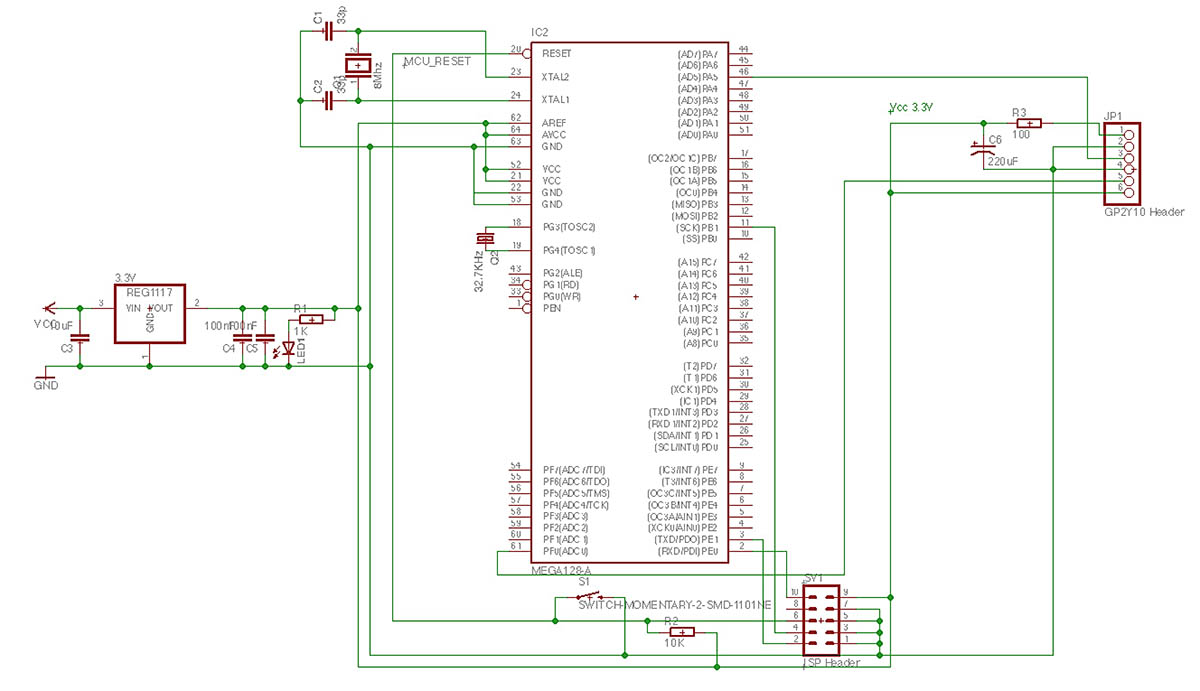
So it might be a good idea to use the PIN 1 V-LED resistor just to make sure the LED enjoys a longer life. For my 3.3V test circuit I've used an 100Ohm resistor and a 22uF capacitor. The circuit becomes:
Reading the output![GP2Y1010AU0F_circuit]()
As said if your supply is well filtered, you can leave the capacitor aside.This is an analogue sensor. The principle of operation is to switch the IR led on, wait a little time then read the output via the ADC port and turn the IR led off. Dust in air would shine under the focused IR light and the phototransistor would read the light output, returning a proportional voltage.
To turn the IR led on, the Green pin 3 (LED) must be pulled to GND. To turn it off, it must be pulled high (Vcc). So on our microcontroller, we need to define the controlling pin as a logical output (I selected PORTA's PA5 on the atmega128), with an initial state of 1, so the led if off by default. Then when we want to read the dust level, we simply pull it down.- DigitalPin dust(&PORTA, PA5, DigitalPin::OUTPUT, true); // PA5 is high by default
- ...
- int main(void) {
- aux_ADCInit(); // enable ADC so we can read the sensor's output
- dust = 0; // led on
- _delay_us(50);
- uint16_t adcValue = aux_ADCRead(PF0); // ADC conversion
- dust = 1; //led off
- }
The ADC is configured for 10bit resolution and the ref is set to AVCC connected to VCC's 3.3V. The adcValue goes from 0 (when the voltage on PF0 is 0) to 1023 (when the voltage on PF0 is 3.3V). Inserting a stick in the sensor's hole is equivalent to the maximum dust reading (sensor totally blocked by dust) and returns a value of 772 (max being 1023).
Converting the valuesUsing the ADC output, we can compute the voltage on the PF0 pin (black pin 5 on the sensor).
- adcVoltage = adcValue * (3.3 / 1024);
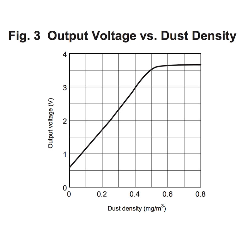
For our maximum dust level of 772, the voltage would be 2.48V . This is the maximum voltage output (with small variations depending on calibration of each particular sensor) of the GP2Y1010AU0F sensor when used in a 3.3V circuit. To interpret the readings, we head back to the datasheet that shows how to interpret the data:
![sharp_1_GP2Y1010AU0F]()
This is good to give an idea, but we have two problems:
- we have voltage and we want to know the dust concentration (the chart shows the inverse function)
- our voltage interval is 0 to 3.3V, not 0 to 5V like in the datasheet.First, fixing the voltage output. Some sources went on uber-complicated aproaches, including dc converters and level shifters. The solution is much simpler, as ADC is a very proportional mechanism. All we need to do is to scale the output according to a 5V maximum:
- adcVoltage = adcValue * (5.0 / 1024);
There, we now have 5V scaled output values , and our maximum value (with stick inserted) goes up to .. 3.76Volts, well consistent with the datasheet maximum (also note that 3.76 x 3.3 / 5.0 = 2.48, the ratio 3.3/5.0 being our scaling factor ). Having the voltage values scaled conveniently, all that's left is interpreting them.
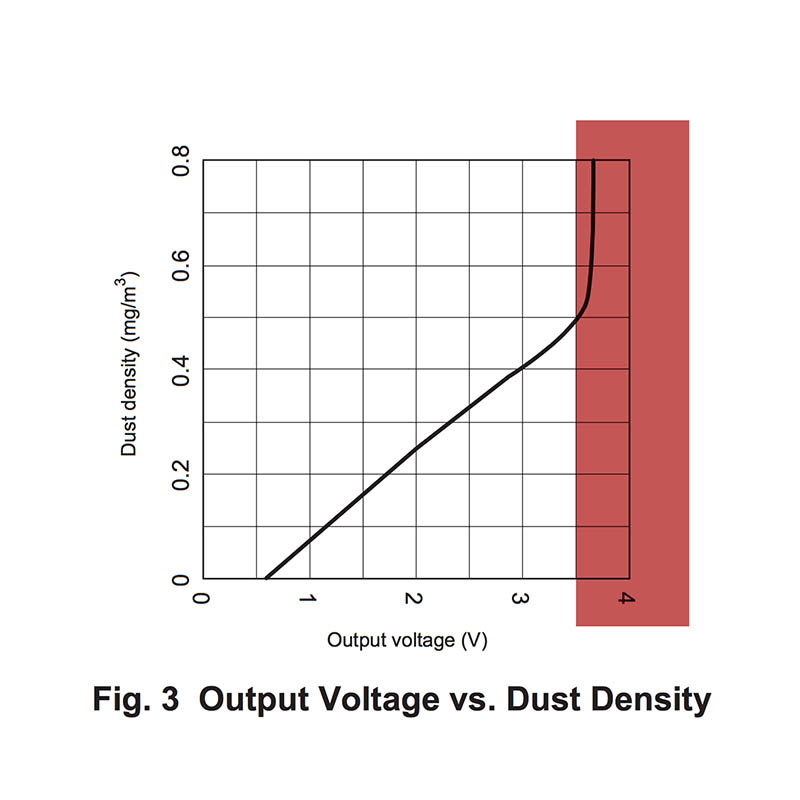
The datasheet function in Fig.3, shows an almost linear function in the interval [0, 0.5] . Our goal is to compute the inverse of this function, but the part from [0.5,] where the function goes quasi-horizontal is not surjective, so it cannot be inversed. But if we define the function on the [0, 0.5] only, an inverse is possible, and it looks like this:![sharp_2_GP2Y1010AU0F]()
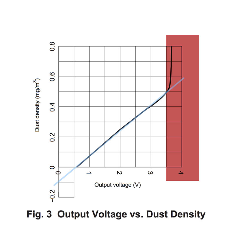
We can accept, with minor errors, a linear approximation of this function, following the blue line in the following image:![sharp_3_GP2Y1010AU0F]()
As the blue line shows a linear function, we can determine it by knowing only two points. Let's name this function "Fl", and it's form is Fl(x) = a*x + b.
We need to find two points (x1, Fl(x1)) and (x2, Fl(x2)) . Given the cartesian coordinates, it's easy to approximate the following values: x1 = 0 where Fl(x1) = -0.1 and x2 = 3.5 where Fl(x2) = 0.5 , both placed in convenient locations.
Using these two, we can compute factor a, or the slope of this function, as: a = (Fl(x2) - Fl(x1)) / (x2 - x1) or a = 0.5 - (-0.1) / 0.35 - 0 = 6 / 35 = 0.1714
Knowing a, we replace it in the function's formula and using one of the two known points we can determine b:
Fl(x2) = a*x2 + b or 0.5 = 6/35 * 3.5 + b quickly resulting that b is -0.1
Our Fl function becomes Fl(x) = 6*x/35 - 0.1 (approximated to Fl(x) = 0.17*x -0.1), the input x is in volts and the output is the dust density in mg/m³. As dust concentration cannot be negative, we will disclose all invalid voltage values. The limit is defined by 6*x/35 - 0.1 = 0 , where x becomes 0.583 volts.
The conversion code is:- DigitalPin dust(&PORTA, PA5, DigitalPin::OUTPUT, true); // PA5 is high by default
- ...
- int main(void) {
- aux_ADCInit(); // enable ADC so we can read the sensor's output
- dust = 0; // led on
- _delay_us(50);
- uint16_t adcValue = aux_ADCRead(PF0); // ADC conversion
- dust = 1; //led off
- adcVoltage = adcValue * (5.0 / 1024);
- if (adcVoltage < 0.583)
- dustConcentration = 0;
- else
- dustConcentration = 6 * adcVoltage / 35 - 0.1;
- }
Article posted on my blog, underhttp://www.pocketmagic.net/sharp-gp2y10-dust-sensor/
-
The WLAN
07/29/2015 at 11:17 • 0 commentsDesigning the wifi interface using the ESP8266 was not easy as I ran into several problems costing me precious time. I got a few esp8266 modules back in 2014, shortly after they've been announced on HackaDay. I didn't have much time for them, being caught with other projects, up until recently when the portable environmental monitor project needed a versatile wireless communication mechanism, low powered and if possible at a decent price. The esp8266 seemed the best candidate, but like with everything in life where nothing comes free, getting it going was not that simple. Here's an article with things that helped me do some ESP8266 Troubleshooting.
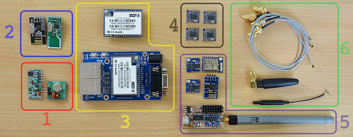
Using the ESP8266![wireless_adapters_comparison]()
The pictures shows:
1.FS1000A / XY-FST Radio module
2.NRF24L01 transceivers
3.HLK-RM04 UART Wifi module and test base board
4.Realtek RTL8188 Wifi modules
5.Various ESP8266 modules 5.SMA cables and antennas
I had to opt-out the low level radio modules, the FS1000A and the NRF24L01 because I needed to follow a standard that would make connecting my devices easier. By using any Wifi 802.11X compatible module, the portable environmental monitor can be connected to any home internet access point, without additional hardware. Being left with 3 choices, I went for the ESP8266 because its low cost and popularity. Both the ESP8266 and the HLK-RM04 are full stack wifi modules, but the latter is larger and my PCB space was limited. The RTL8188 only contains the MAC and the PHY, so this complicates the software; it also uses an USB interface, incompatible with my current microcontroller choice, the atmega128.There are several types of ESP8266 modules. Those in my toolbox included the ESP-01, ESP-02, ESP-04, ESP-05 and ESP-07. For my project I needed an all-SMD module with exposed antenna pin instead of the small IPEX connector, so I can use my own SMA antenna connector. The ESP-04 fits all these requirements, still for a first test I went with the ESP-01 due to its breadboard friendly pins. My plan was simple, hook it to the 3.3V powered atmega128 board UART pins and write some simple serial communication code (send AT\r\n etc).
ESP8266 Troubleshooting![atmega128_ili9341_esp8266]()
The esp8266 ESP-01 I had was configured for 115200bps. The ESP-04 and the ESP-05 were both set to 9600bps. These baudrates can vary depending on the firmware, but 9600 and 115200 are the two common values.
At first I had little luck getting the atmega128 to communicate with the Wifi module, due to some errors in my code. It is just a simple UART communication, nothing fancy, but the 115200 value overflown the integer limit of my baudrate variable. This got me hooking the ESP8266 module directly to my computer via a FT232 USB to UART module, modified for 3.3V. The FT232 must make common ground with the ESP8266. Under MacOS I used both the screen terminal command and the CoolTerm app to communicate with the modules.
The UART0 was connected to the ESP8266 and communication displayed on the ILI9341. UART1 was connected to the computer, via a FT232 module to sniff the traffic.
Things that didn't work at first:
- integer baudrate variable was too small for the 115200 value, resulting in wrong baudrate setting, and weird output characters
- sent AT commands if not terminated in \r\n just returned an echo instead of doing their job.
- for all modules other than the ESP-01, the GPIO15 must be grounded, or strange characters will appear
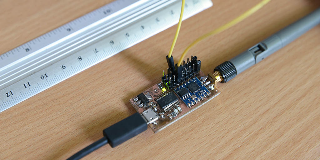
- the CH_PD must be pulled high (connected to Vcc)Custom test boardTo make testing easier I also built a nice USB to Wifi module, to push my soldering skills to the limit but also see how well I can design a working board with the FT232RL, the ESP-04 and a SMA antenna connector.
![usb2wifi_ft232rl_esp8266]()
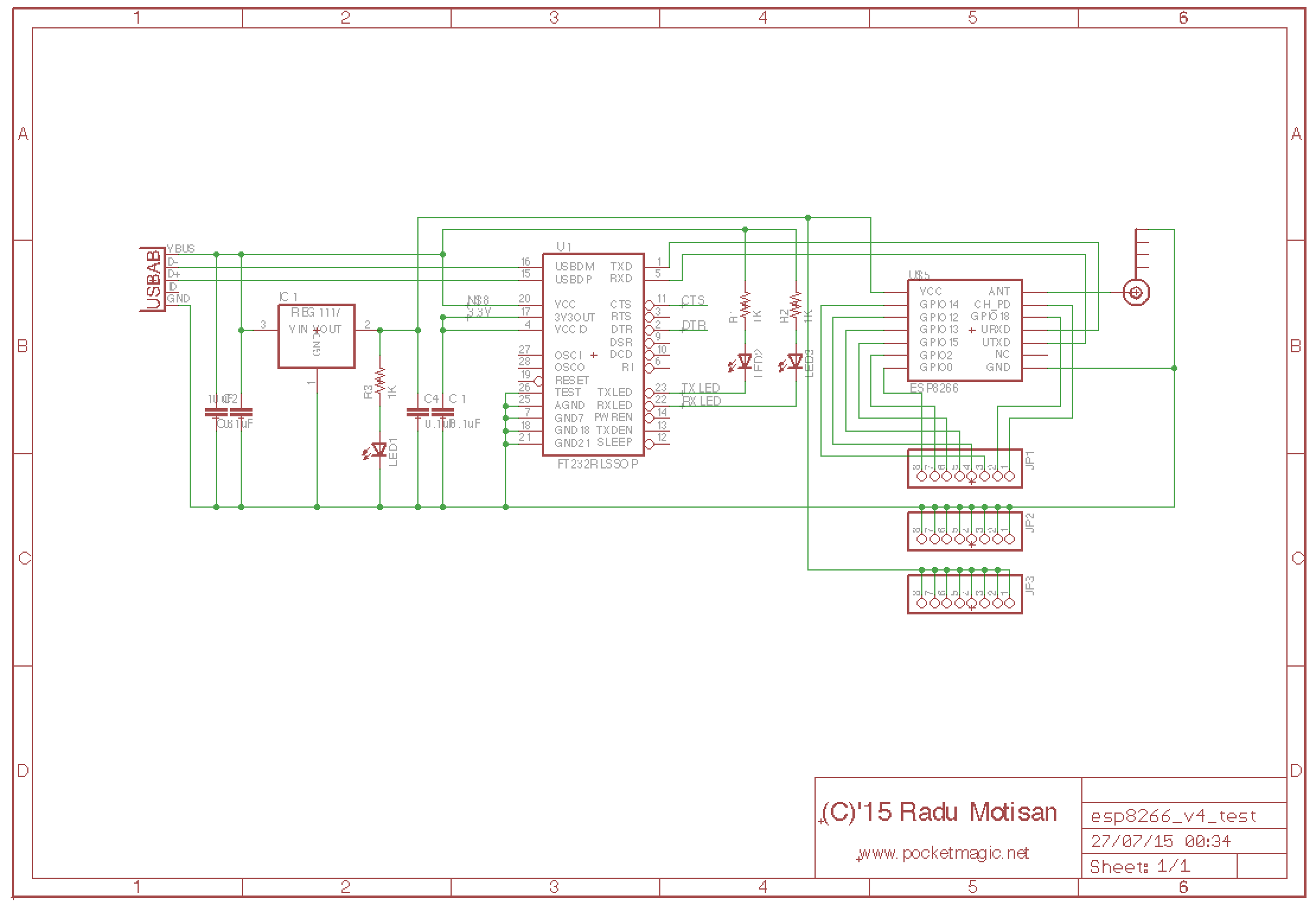
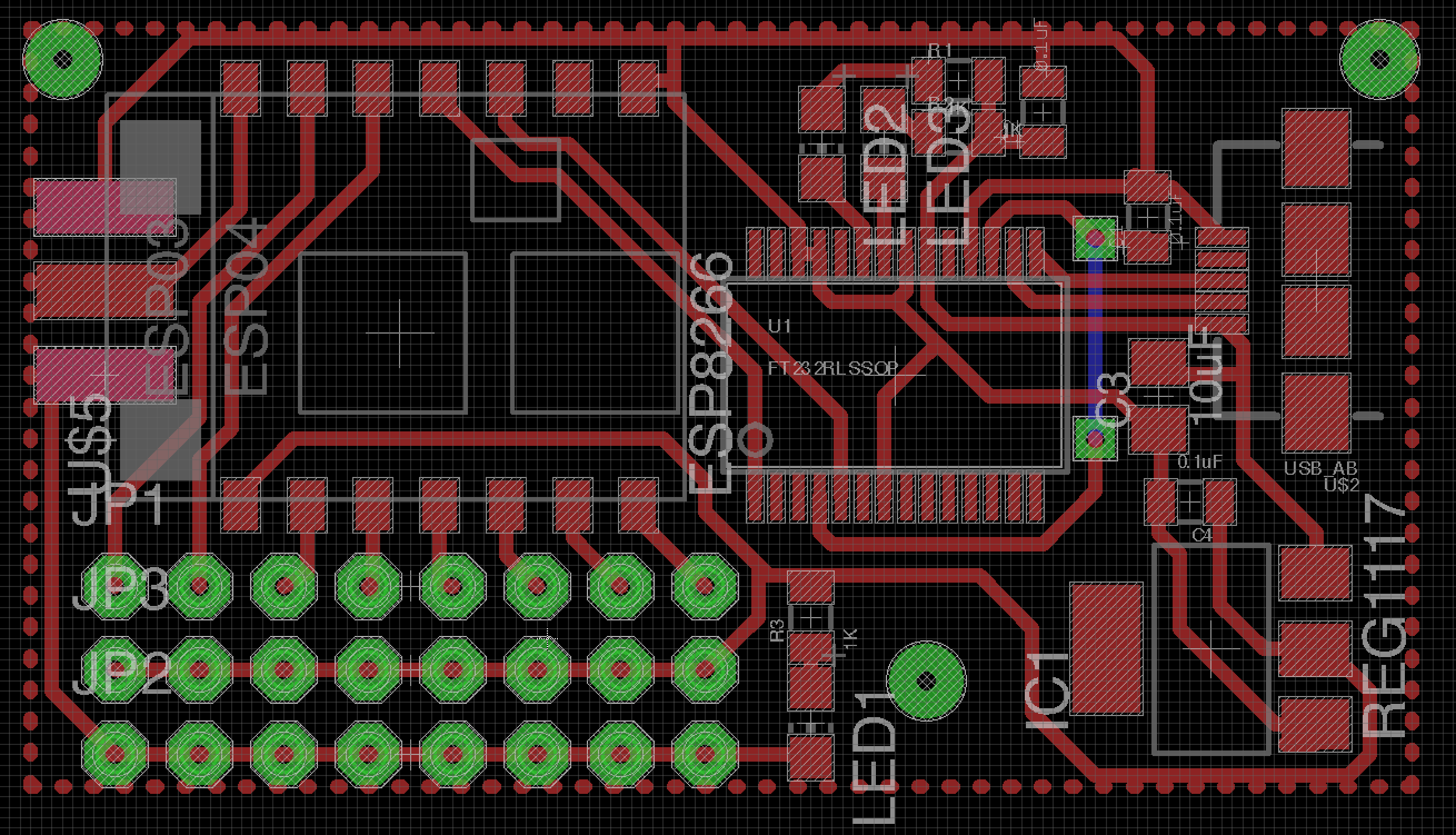
It came out nice, and proved to be very useful for testing the ESP8266 AT commands before designing a parser to run on a microcontroller.![esp8266_board_sch]()
![esp8266_board_brd]()
![ft232rl_eps8266_converter]()
Eagle design files are available here: http://www.pocketmagic.net/esp8266-troubleshooting/
-
The LCD, the touchscreen and the software
07/23/2015 at 16:19 • 0 commentsThe project uses the ILI9341 16bit display and a touchscreen for input. All buttons will be virtual except the power on/off. While working on the ILI9341 LCD library I also coded a simple Paint application to test everything working together:
The library code is released as open source, details on http://www.pocketmagic.net/ili9341-touchscreen-lcd-library/
-
atmega128 voodoo
07/15/2015 at 13:41 • 0 comments![atmega128_voodoo_2]()
"Any improbable event which would create maximum confusion if it did occur, will occur."
While working on my Hackaday 2015 Prize project, the two development boards I was using, both based on atmega128 started to behave erratically. The issue made me blame parts of code related to the esp8266 or the ILI9341 modules, and I wasted a lot of time. Finally I stripped the code down to a blinking LED, just to see that the original Voodoo issue is back. No 5V programmer would make it go away this time.
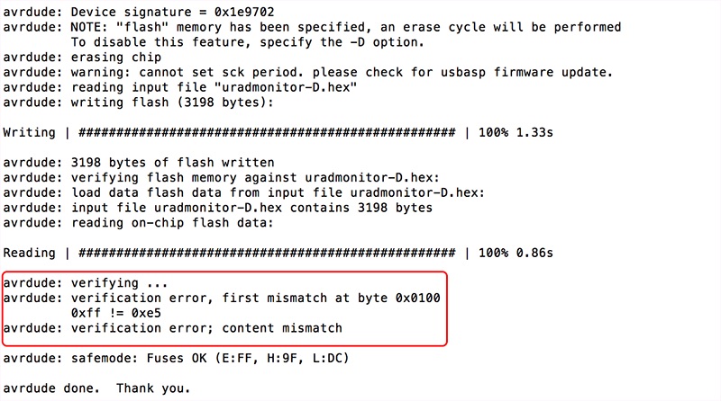
This almost made me switch to STM32F4 microcontrollers as an alternative, but the time was too short for that, as the volume of code needed to be ported was too high. So back to AVRs, I purchased a few alternatives like the mega64, various programmers (initially I used usbAsp with avrdude under MacOS) hoping to find a working solution. Which I did not. This didn't stop me from rechecking everything over and over again. Between several inconsistent software runs, I noticed a code verification error, "first mistmatch at byte 0x0100" and "verification error; content mismatch":![avrdude_first_mistmatch_at_byte_0x0100]()
Tracking the issue I ended up on the avrdude website and their bug tracking system, where bug #41561 presented just that, but for the atmega64. Apparently a change in avrdude 5.11 introduced memory tagging, as explained by Joerg Wunsch :Before, all memories had been treated as a large block of bytes (N = size of that memory area on the chose device), regardless of whether their contents actually came from an input file. Now, only those regions are touched that have corresponding bytes in the input file. (For paged memory areas, the term "region" here refers to the situation where at least one byte within a memory page has been mentioned in the input file.)
I traced the ISP traffic with a logic analyzer, and decoded the data stream back into ISP commands. See the attachment for the full trace. The bug is that the "write memory page" command is issued twice:Time 393.416 ms: MOSI Load program memory page, address 0x007f, low byte, value 0x6d
After filling the page buffer, the page is being programmed at time 394.370 ms. Then, USBasp polls the page for a response != 0xff, which indicates the end of the write operation (time 398.805 ms). However, just after this, it issues another "write page" command at 399.222 ms, but then proceeds to fill the page buffer again for the next page.
Time 393.910 ms: MOSI Load program memory page, address 0x007f, high byte, value 0x6d
Time 394.370 ms: MOSI Write program memory page, address 0x007f
Time 394.804 ms: MOSI Read program memory, address 0x007f, high byte, value 0xff
Time 395.218 ms: MOSI Read program memory, address 0x007f, high byte, value 0xff
Time 395.688 ms: MOSI Read program memory, address 0x007f, high byte, value 0xff
Time 396.131 ms: MOSI Read program memory, address 0x007f, high byte, value 0xff
Time 396.538 ms: MOSI Read program memory, address 0x007f, high byte, value 0xff
Time 397.013 ms: MOSI Read program memory, address 0x007f, high byte, value 0xff
Time 397.427 ms: MOSI Read program memory, address 0x007f, high byte, value 0xff
Time 397.903 ms: MOSI Read program memory, address 0x007f, high byte, value 0xff
Time 398.368 ms: MOSI Read program memory, address 0x007f, high byte, value 0xff
Time 398.805 ms: MOSI Read program memory, address 0x007f, high byte, value 0x6d
Time 399.222 ms: MOSI Write program memory page, address 0x007f
Time 399.686 ms: MOSI Read program memory, address 0x007f, high byte, value 0x6d
Time 401.510 ms: MOSI Load program memory page, address 0x0080, low byte, value 0x6f
Time 402.139 ms: MOSI Load program memory page, address 0x0080, high byte, value 0x72
Apparently, the old devices (ATmega64/128) respond to the second page write immediately with a poll value of "OK" (i.e., they return the correct value), yet they are still busy programming afterwards. In contrast, the newer devices (like ATmega1281) correctly respond again with 0xff for the second page write operation:Time 391.417 ms: MOSI Load program memory page, address 0x007f, low byte, value 0x6d
which explains why they can be programmed fine. But obviously, the second page write operation is completely unnecessary.
Time 391.910 ms: MOSI Load program memory page, address 0x007f, high byte, value 0x6d
Time 392.371 ms: MOSI Write program memory page, address 0x007f
Time 392.806 ms: MOSI Read program memory, address 0x007f, high byte, value 0xff
Time 393.218 ms: MOSI Read program memory, address 0x007f, high byte, value 0xff
Time 393.689 ms: MOSI Read program memory, address 0x007f, high byte, value 0xff
Time 394.130 ms: MOSI Read program memory, address 0x007f, high byte, value 0xff
Time 394.539 ms: MOSI Read program memory, address 0x007f, high byte, value 0xff
Time 395.014 ms: MOSI Read program memory, address 0x007f, high byte, value 0xff
Time 395.428 ms: MOSI Read program memory, address 0x007f, high byte, value 0xff
Time 395.903 ms: MOSI Read program memory, address 0x007f, high byte, value 0xff
Time 396.369 ms: MOSI Read program memory, address 0x007f, high byte, value 0xff
Time 396.806 ms: MOSI Read program memory, address 0x007f, high byte, value 0x6d
Time 397.222 ms: MOSI Write program memory page, address 0x007f
Time 397.687 ms: MOSI Read program memory, address 0x007f, high byte, value 0xff
Time 398.130 ms: MOSI Read program memory, address 0x007f, high byte, value 0xff
Time 398.539 ms: MOSI Read program memory, address 0x007f, high byte, value 0xff
Time 399.013 ms: MOSI Read program memory, address 0x007f, high byte, value 0xff
Time 399.431 ms: MOSI Read program memory, address 0x007f, high byte, value 0xff
Time 399.903 ms: MOSI Read program memory, address 0x007f, high byte, value 0xff
Time 400.368 ms: MOSI Read program memory, address 0x007f, high byte, value 0xff
Time 400.805 ms: MOSI Read program memory, address 0x007f, high byte, value 0xff
Time 401.218 ms: MOSI Read program memory, address 0x007f, high byte, value 0xff
Time 401.688 ms: MOSI Read program memory, address 0x007f, high byte, value 0x6d
Time 403.640 ms: MOSI Load program memory page, address 0x0080, low byte, value 0x6f
Time 404.155 ms: MOSI Load program memory page, address 0x0080, high byte, value 0x72
The difference ... is that AVRDUDE now works on a per-page basis throughout all programmers, rather than on the entire device memory. If I remove the USBASP_BLOCKFLAG_LAST (line 1330, function usbasp_spi_paged_write()), it seems to work as intendedAnd indeed it works! Personally I opted for using a version prior to 5.11 (CrossPack-AVR-20100115.dmg), as that was readily available for MacOS, but as soon as I finish my work for the HackADay Prize 2015, I'll have the time to properly compile the latest code that fixes the issue.
-
The Radiation Sensor
07/05/2015 at 19:06 • 0 commentsOne problematic issue was sourcing the proper detector, one that was both sensitive and small to fit the tiny space available in the already feature-crowded new uRADMonitor variant. After a slow process and intense communication with radiation detector manufacturers, we finally found a good candidate, putting price and performance in a reasonable balance: LND Inc and their excellent LND712 end window Mica Geiger tube.
![uradmonitor_LND712_test_500V]()
To give it a quick test, the tube was hooked to one of the model A boards, and the voltage configured in software from 380V (which is used the SBM-20 and SI-29BG tubes) to 500V! Yes, the model A hardware supports that just fine with no other changes than a single constant changed in code, thanks to the excellent high voltage inverter circuit:![uradmonitor_inverter_target_voltage]()
![uradmonitor_lnd712_voltage]()
The result was as expected, and can be seen in the second image. The voltage on tube measurement is presented, part of the internal inverter feedback mechanism, responsible for having a regulated output matching the target voltage, in this case exactly 500V.![uradmonitor_lnd712_geiger_4]()
Compared to the SBM-20, the LND712 shows the same sensitivity at a smaller size.![uradmonitor_lnd712_cpm]()
But the Alpha and beta radiation sensitivity is the plus we’re after , and we get that just fine thanks to the mica end window.![uradmonitor_lnd712_geiger_2]()
The BOM production cost, however, will inevitably increase, as a single LND712 gets close to $70, the tube only and this is just a little fraction of all the components that need to go in the new model D environmental dosimeter. -
Sensors quest continues
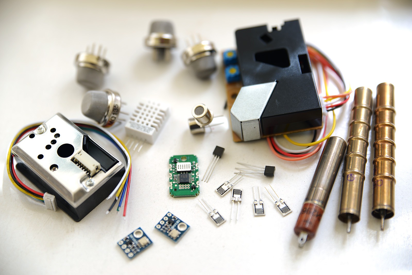
05/08/2015 at 19:20 • 3 commentsI was hoping to have better luck by now with the sensors. I have sorted out the radiation sensors and I'm happy with the alpha and beta radiation solutions, but I am still trying to find a reasonable way for detecting various gases. Dust sensors are also quite big for the enclosure I am planning for these devices:
![]()
For gases, I have two options: affordable, low size semiconductor sensors or costly NDIR sensors. The semiconductor sensors use a lot of power on the filament and have a long pre-heating time. Considering this is a battery powered application, and that we might need to be able to turn some of the sensors on and off depending on the measurements we are interested in, using semiconductor sensors might be challenging.
The NDIR sensors are costly, in the range of hundreds of euros / dollars for a single sensor, and would usually target a single gas only. Their size is not small either. Due to these serious limitations, I won't be able to use NDIR sensors.
Still looking for alternatives.
-
Early design: choosing the sensors
03/27/2015 at 23:06 • 0 commentsSome feedback would be extremely useful at this phase. I will need to choose the best alpha radiation detector, both sensitive, shock resistant and low sized (have contacted radiation detector manufacturers already, hoping for an early reply).
Also the dust sensor is a bit problematic, since most of the off-the-shelf components are relatively big while using simple photoelectric principles. I can go for something custom, but preferably a readily available, calibrated component should be identified.
Finally the air tube depicted in the sketches should allow the temperature sensor to measure the outside temperature, while the porous filter should concentrate radon in close proximity for the alpha detector to do its measurements.
Suggestions are welcome!
Portable environmental monitor
A handheld, battery powered, sensor array unit for environmental monitoring focused mostly on air quality using a global infrastructure.