 Andre Maia Chagas
-
1Step 1
Instructions overview:
This build is pretty simple and consists of few steps:
- Printing the necessary parts from the scad file
- Soldering all necessary components to the PCB
- Setting up the Operating System for the Raspberry Pi
- Fixating components to the printed parts:
- Main body to Raspberry Pi + Peltier + camera
- Micromanipulator
- LED ring and light diffuser
- High Powered LEDs and fluorescence module
- Setting up Arduino and Python code
-
2Step 2
Printing the necessary parts from the scad file
Necessary parts:
- OpenScad (free open source software, can be downloaded here).
- The scad file containing the Flypi's 3D model, can be found on the project page, in files.
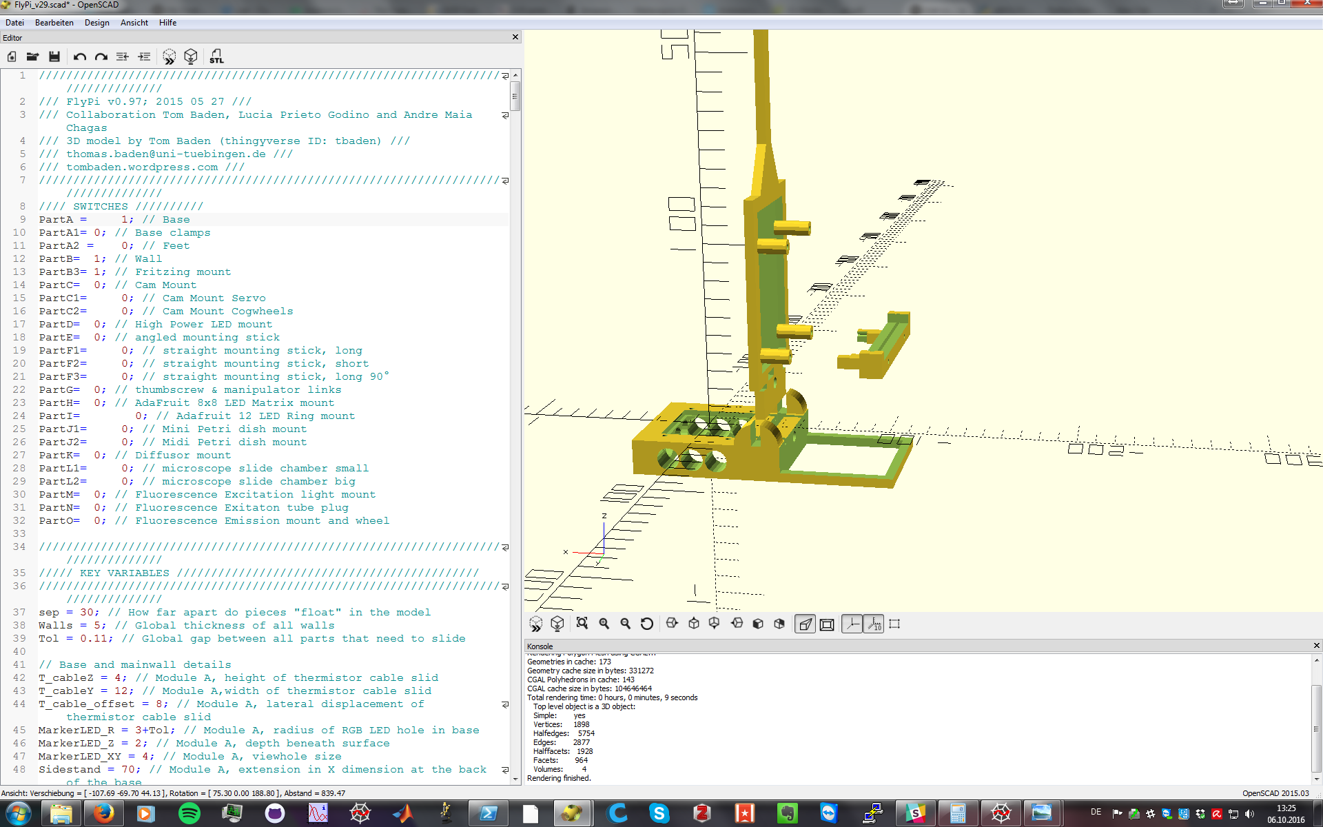
Steps (images below):
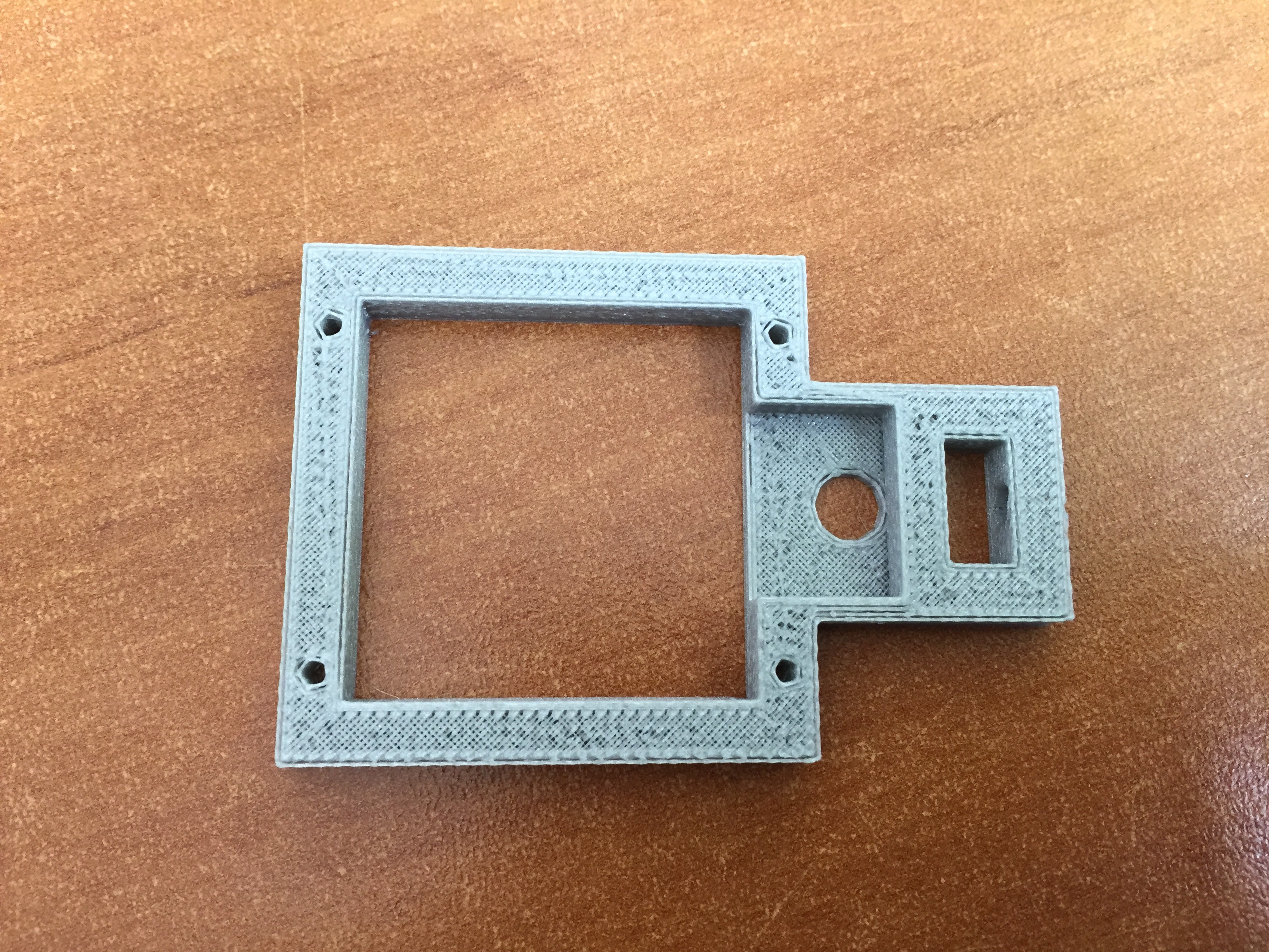
- Use OpenScad and the flags in the script to render the parts necessary (see image below) - If you are only using the microscope module, the only necessary parts are the base, backplate, camera holder.
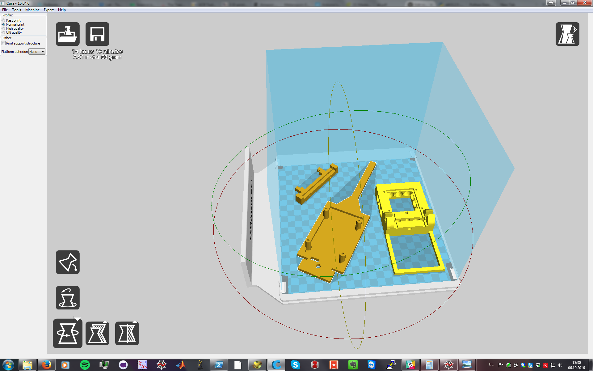
- Convert the rendered parts to .STL (example below using Cura)
- load it to your preferred printer. (15-25% percent infill should be more than enough).
- (Optional step): Print the base, one long arm and the camera holder. After printed, test if the parts slide properly into one another. If they are too loose or too tight, change the "tolerance" parameter on the SCAD file.
- Print away (the complete Flypi can be printed in about 30 hours with a printer running at 40-50 mm/sec and 0.25 layer height).
![OpenScad screenshot, showing bare minimum to be printed]()
![After being exported as STL, a slicing software is used to prepare parts for printing]()
![]()
-
3Step 3
Soldering all necessary components to the PCB
Necessary parts:
- Custom PCB (gerber files necessary to fabricate them are on the project page)
- Electronic components for the modules you want to build.
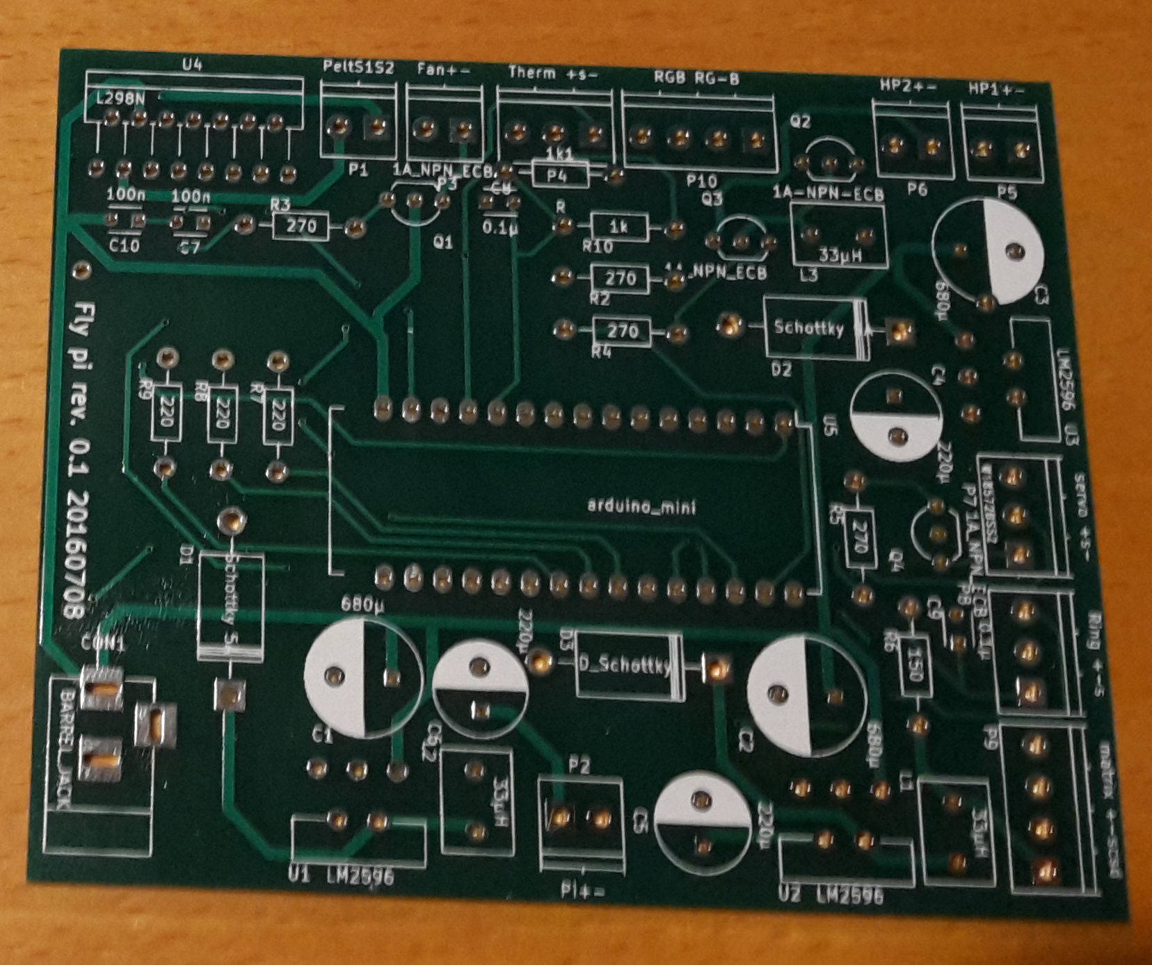
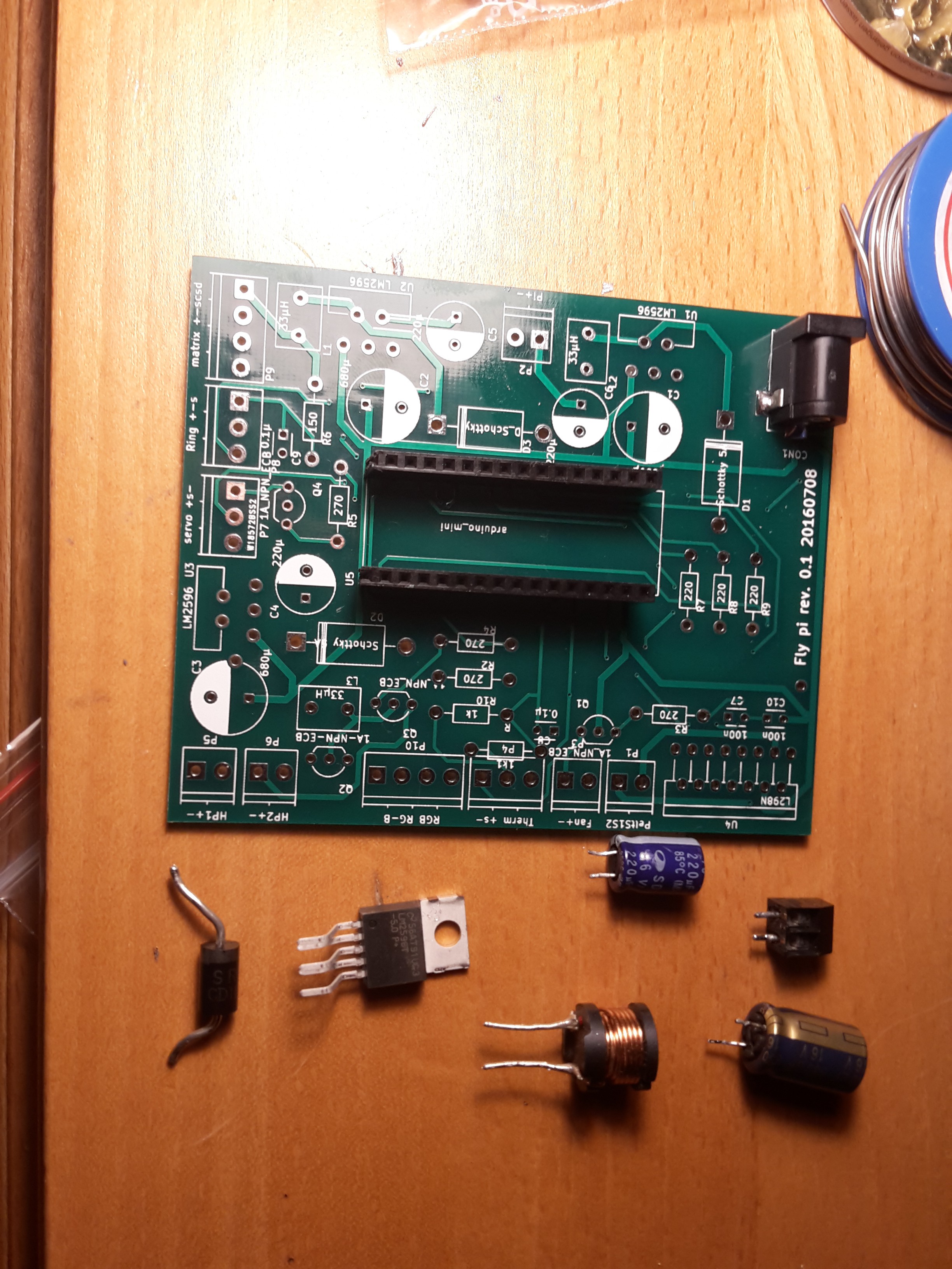
The PCB was designed to be modular. If the user only wants to use the peltier module and the LED ports, than only the components for those parts need to be soldered in. Also, we opted to stay with "through hole" architecture so people won't get stuck while learning how to solder and populating the PCB at the same time.
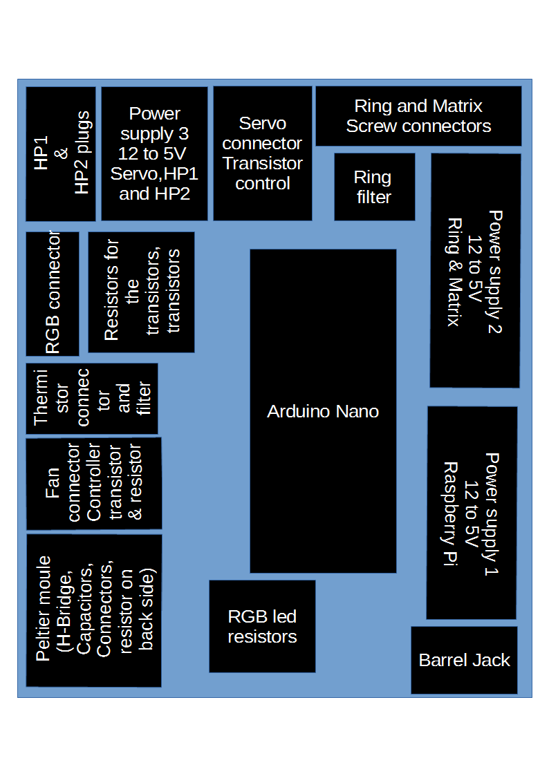
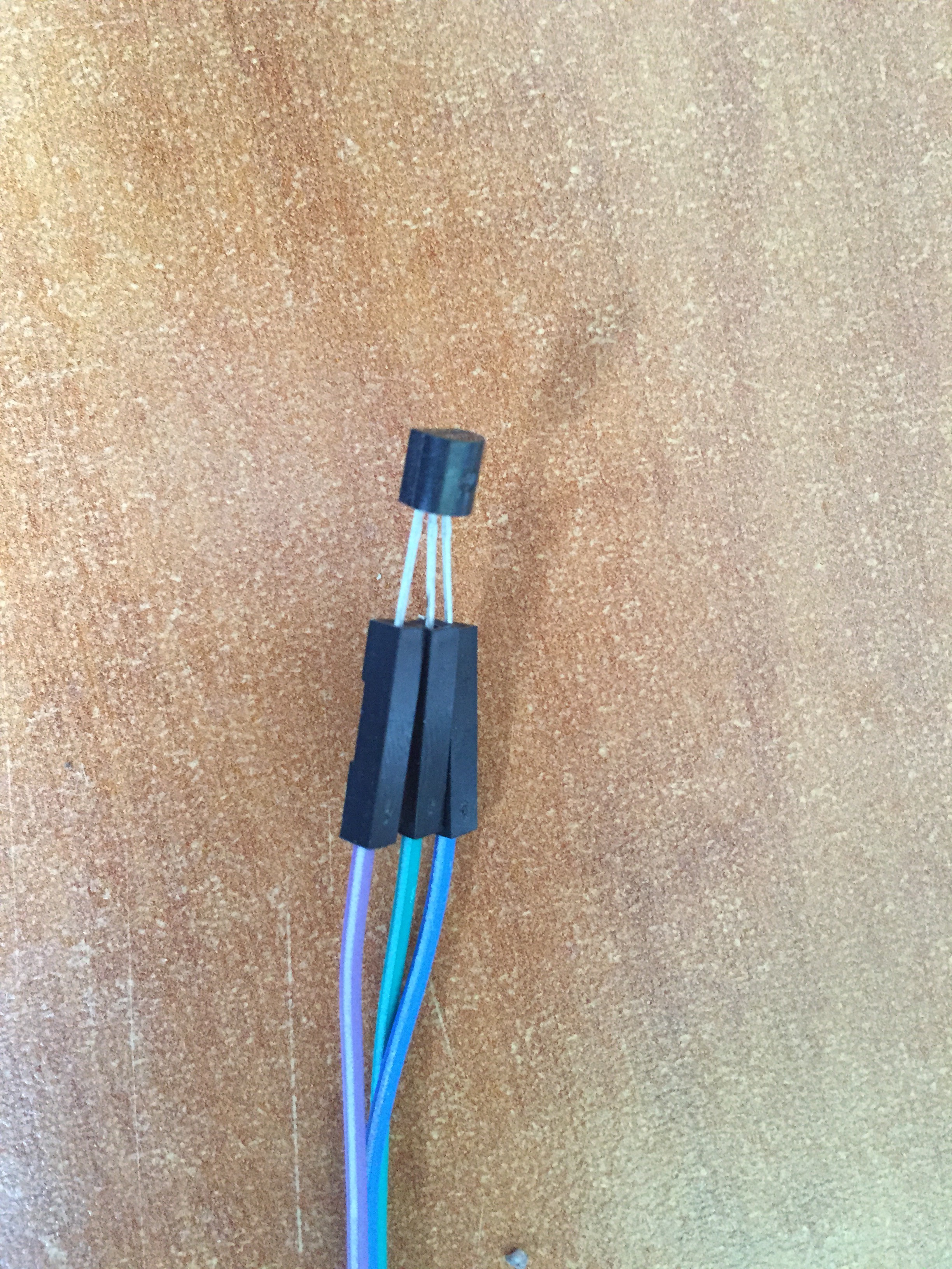
The PCB is annotated (component number and value), so one can read which component goes where (R refers to resistors, C to capacitors, D to diodes, P to screwterminals, U to integrated circuits (ICs), L to inductors and Q to transistors - see image below).
Steps (if building a complete set - images follow below):
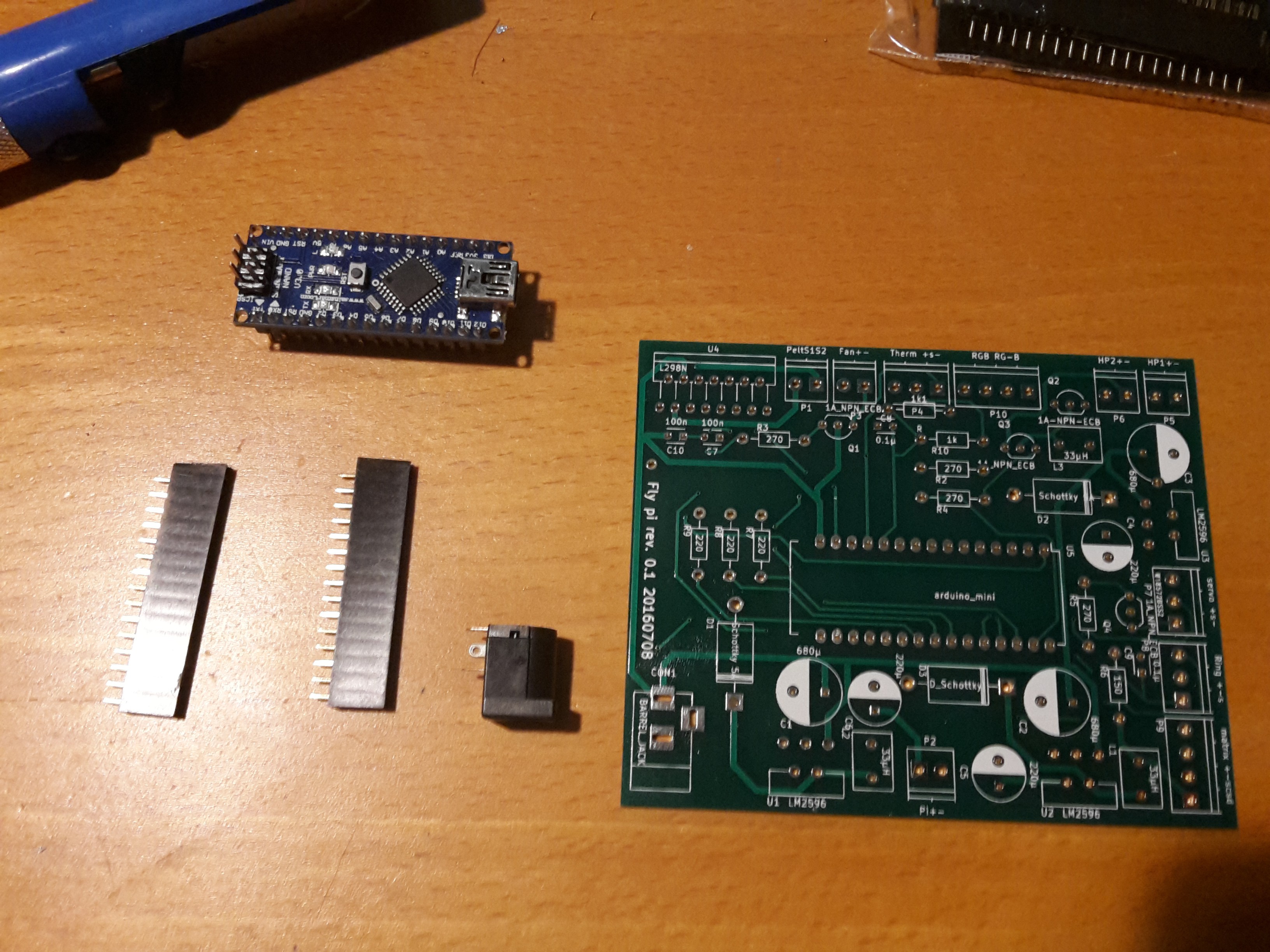
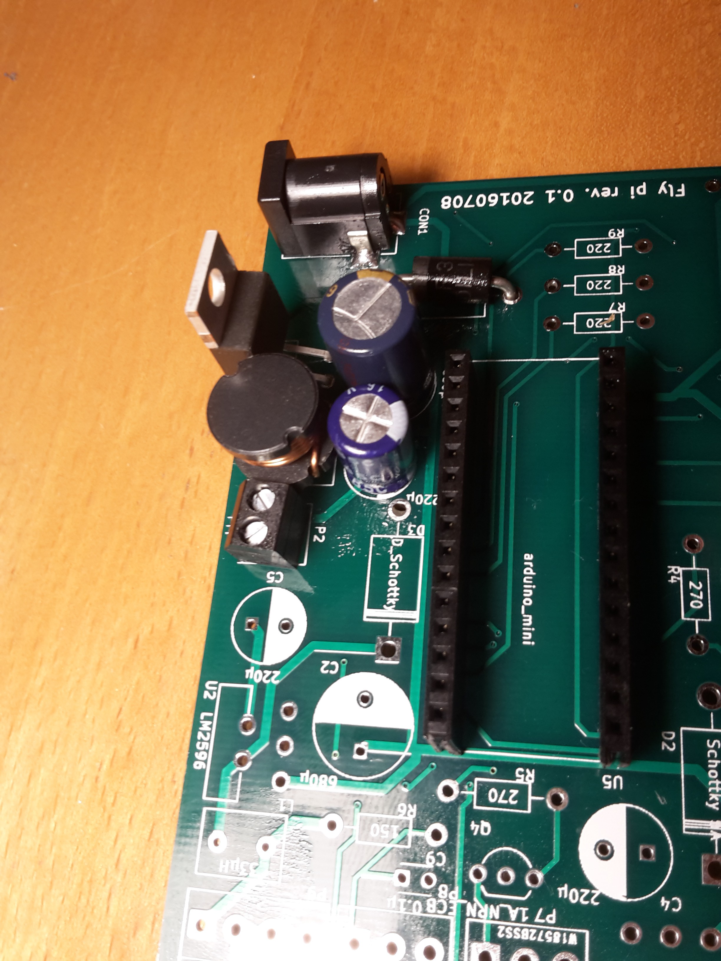
- Start by placing and soldering the smallest components. Good place to start are resistors, transistors and capacitors - remember to check their polarity - (check the schematics below to have an idea of where on the board the modules are distributed). If you are building the Peltier module, leave the big resistor that sits in the back of the board as the very last thing to solder
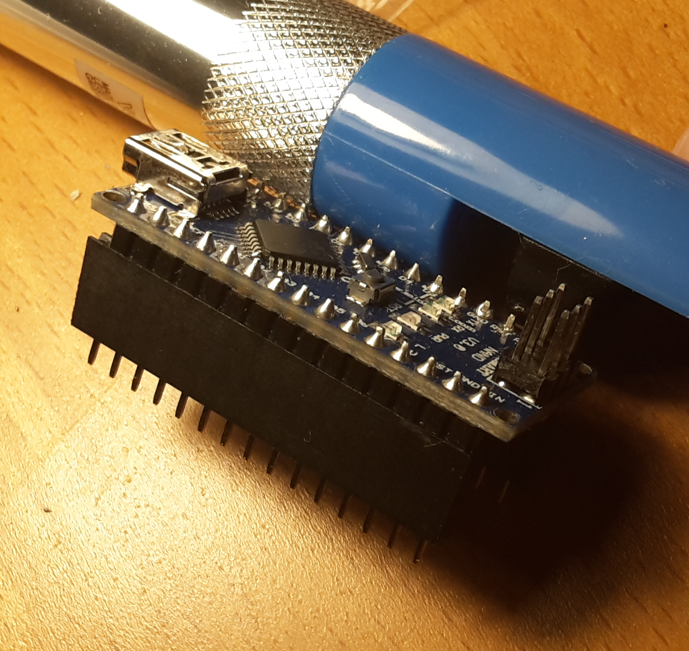
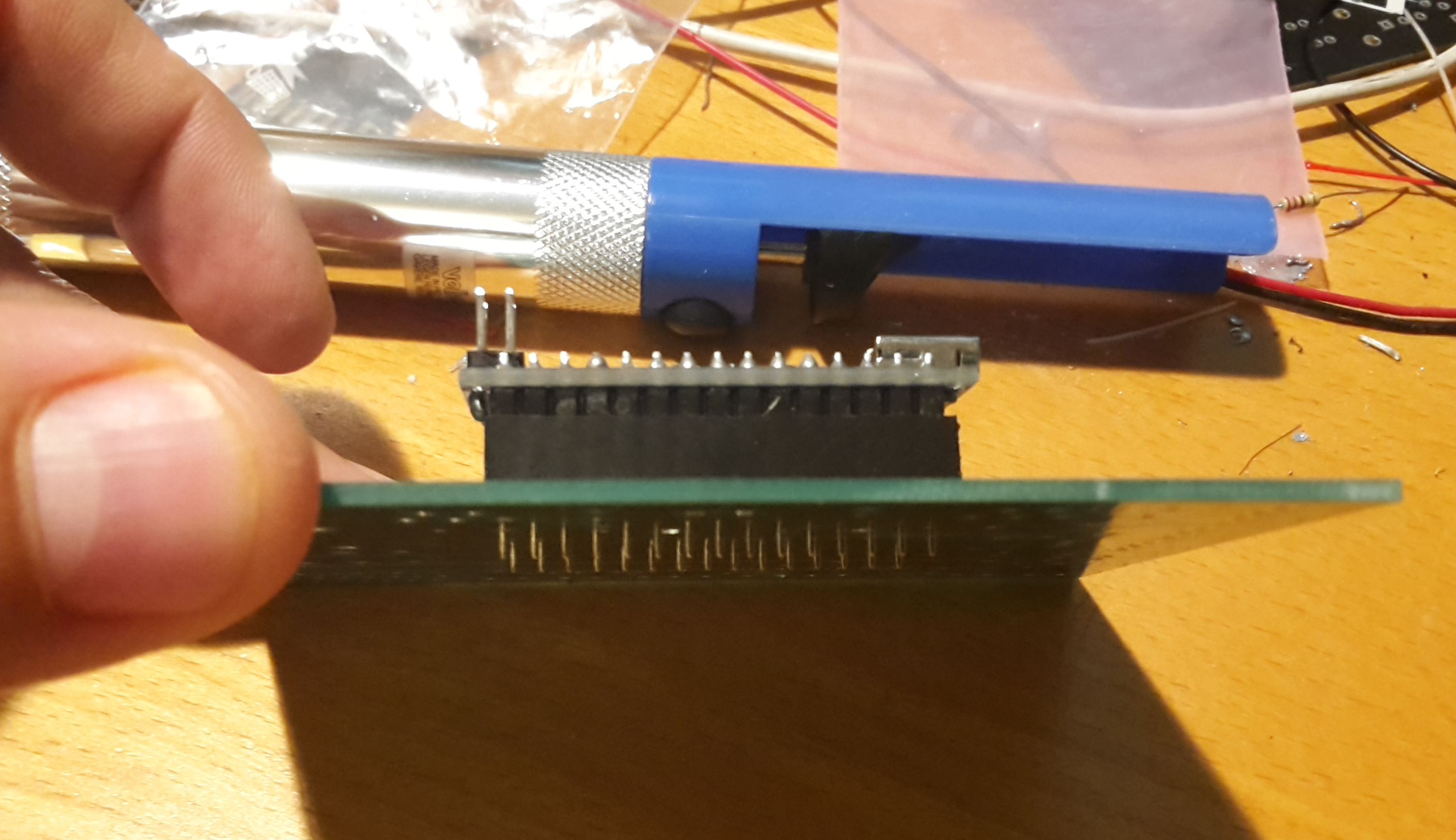
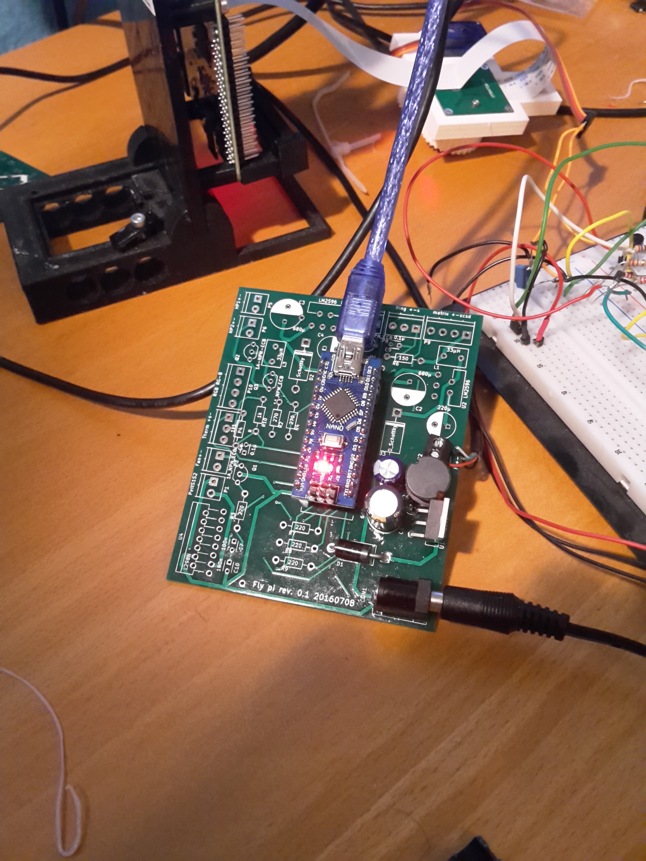
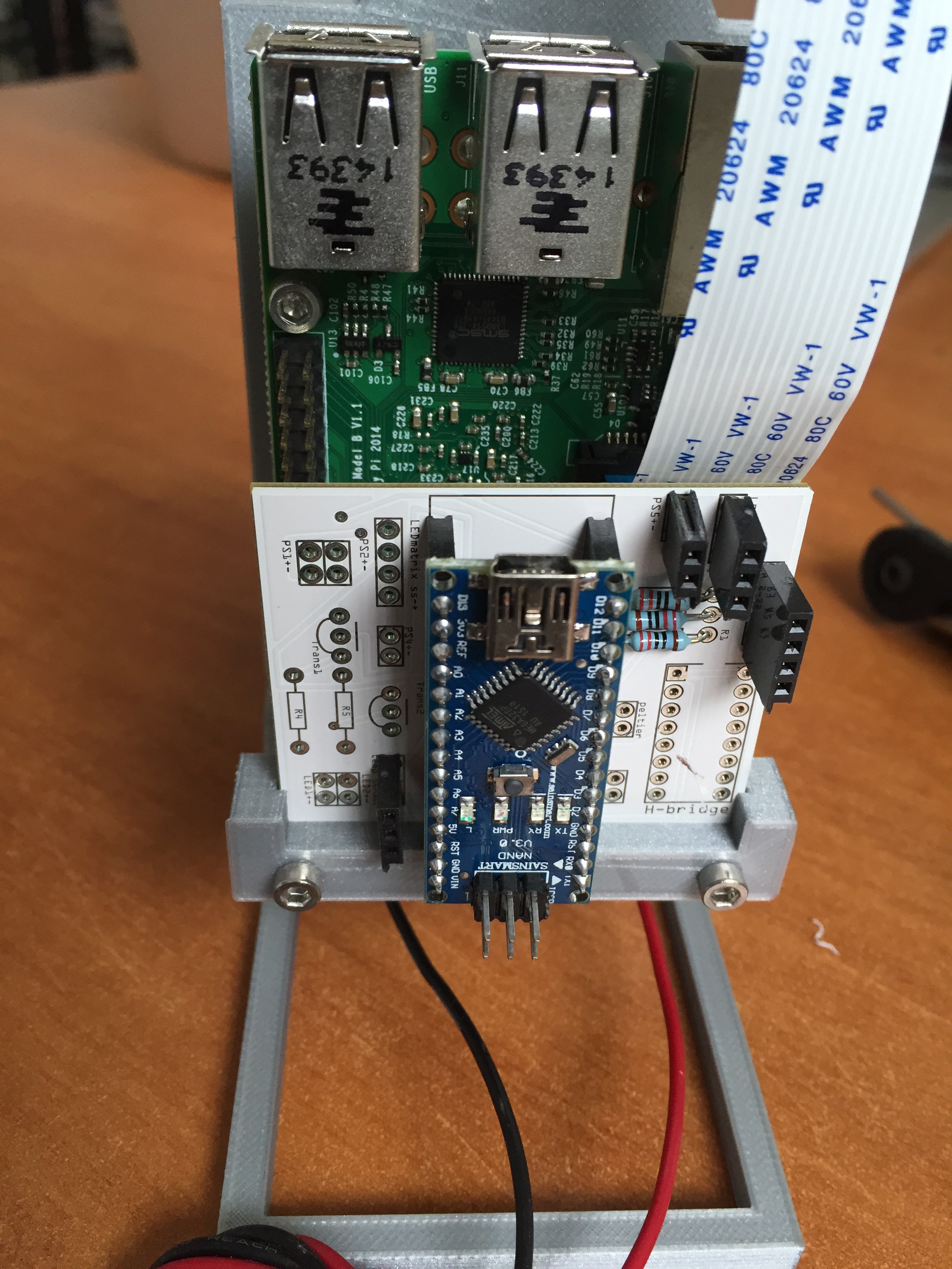
- Move on to ICs, power modules and Peltier first, Arduino with female connectors last. On placing the arduino, it is a good idea to sit the board on female connectors first and then connect those to the PCB (see image below), this way there is less chance of overheating the board, it can be taken off for other projects or in case of damage, and makes alignment of the female connectors easier. Remember that the Arduino USB port should be facing away from the barrel connector
- Last, solder the screw terminals and barrel connector.
![]()
![]()
![]()
![]()
![]()
![]()
![]()
![]()
![]()
-
4Step 4
Setting up the Operating system(OS) for the Raspberry Pi:
Items needed:
- Raspberry Pi
- Micro SD card (we are currently using a 16GB one. Smaller ones can be used, but this is not adviced, as videos and images can fill up the card quickly).
- Laptop/Desktop computer and internet connection
Steps:
- In our build we are using Raspian, but any other compatible OS can be used, as long as it is capable of running Python3 (and preferably the Arduino IDE). To install Raspian on the raspberry pi, we refer users to the excellent guide from the Raspberry Pi foundation.
-
5Step 5
Fixating electronics to printed parts:
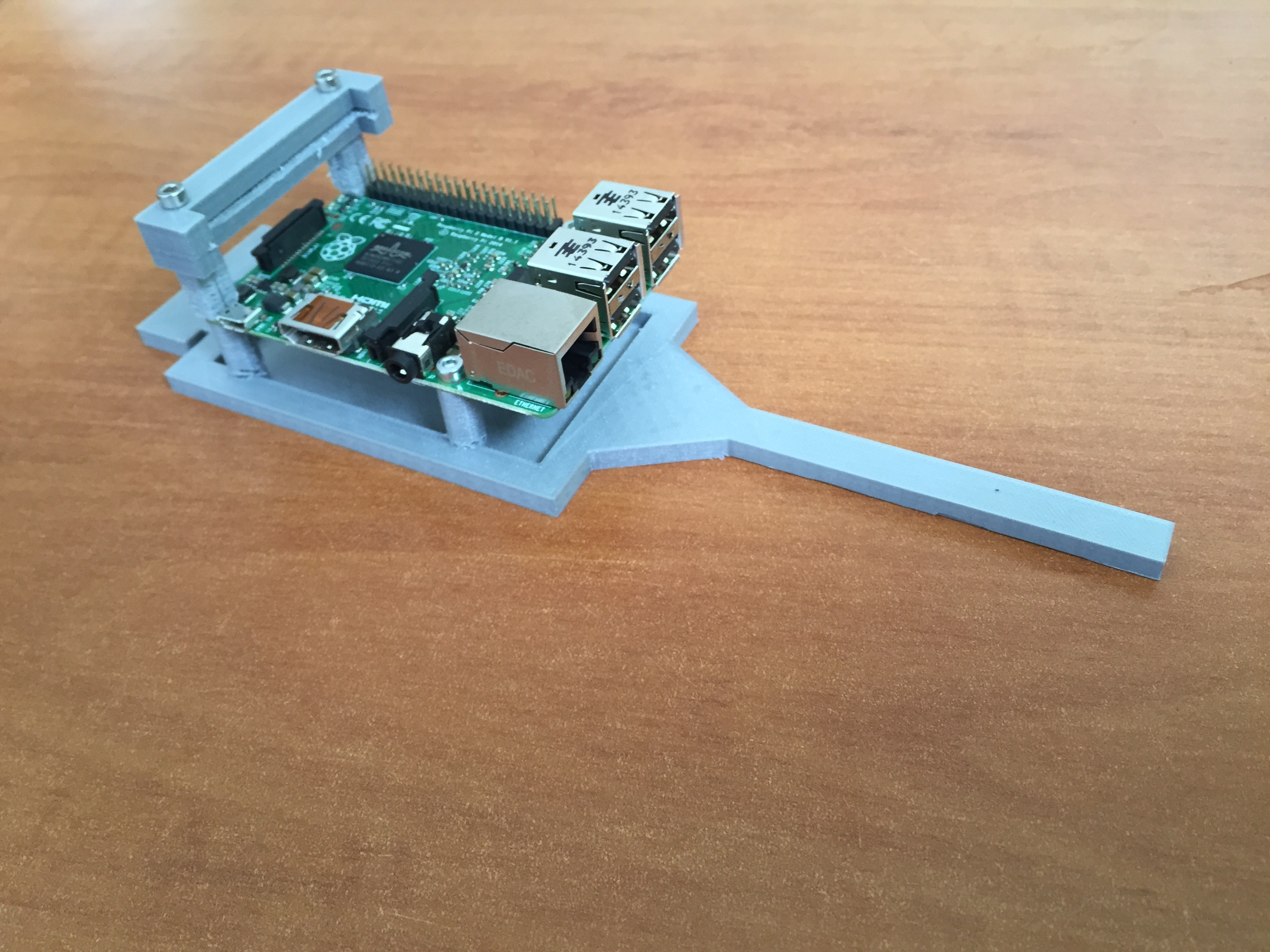
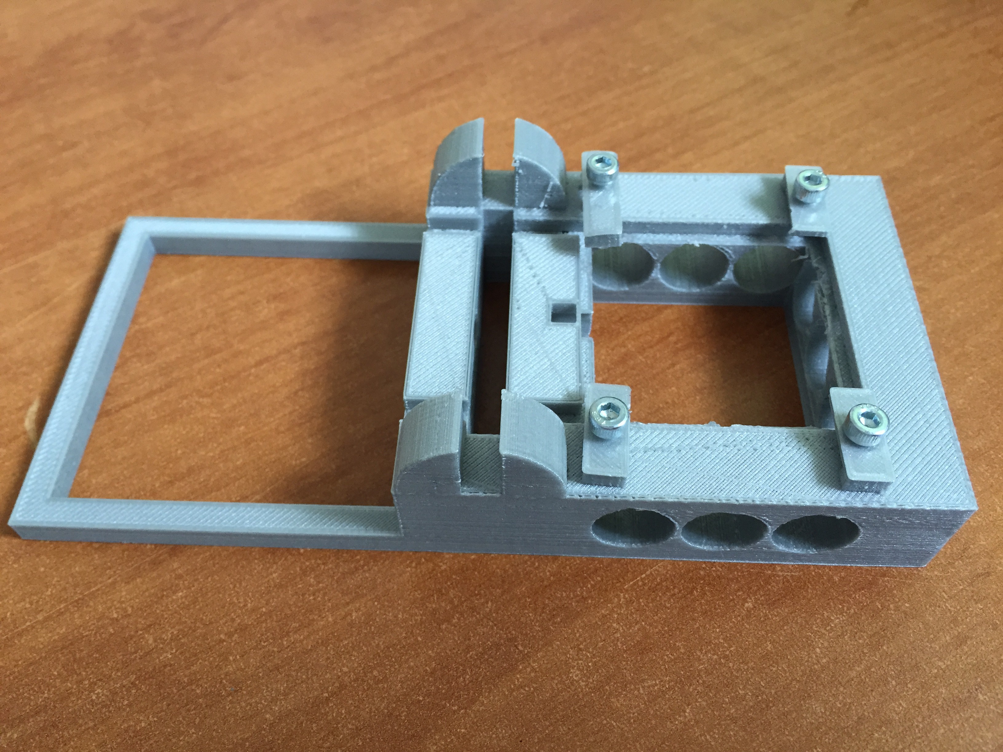
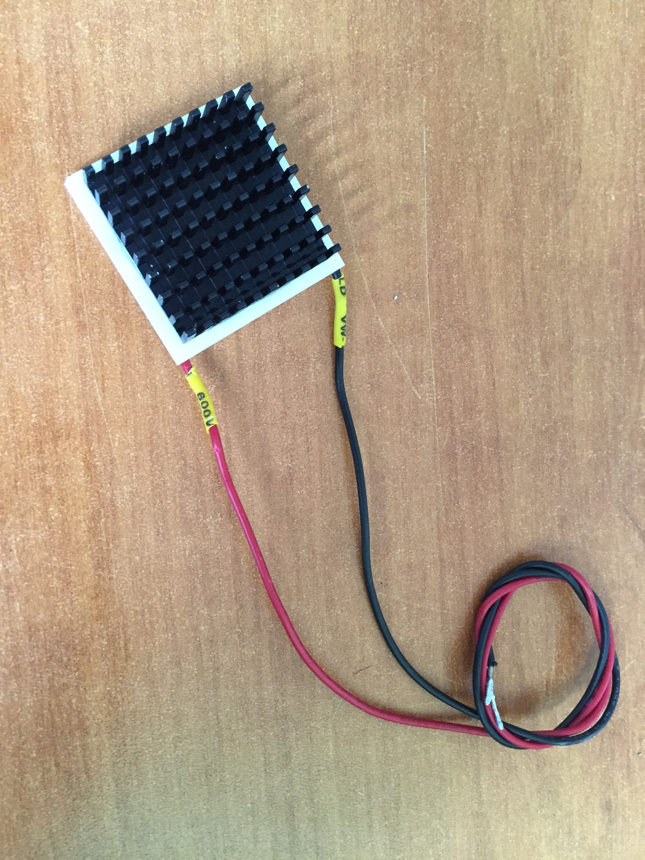
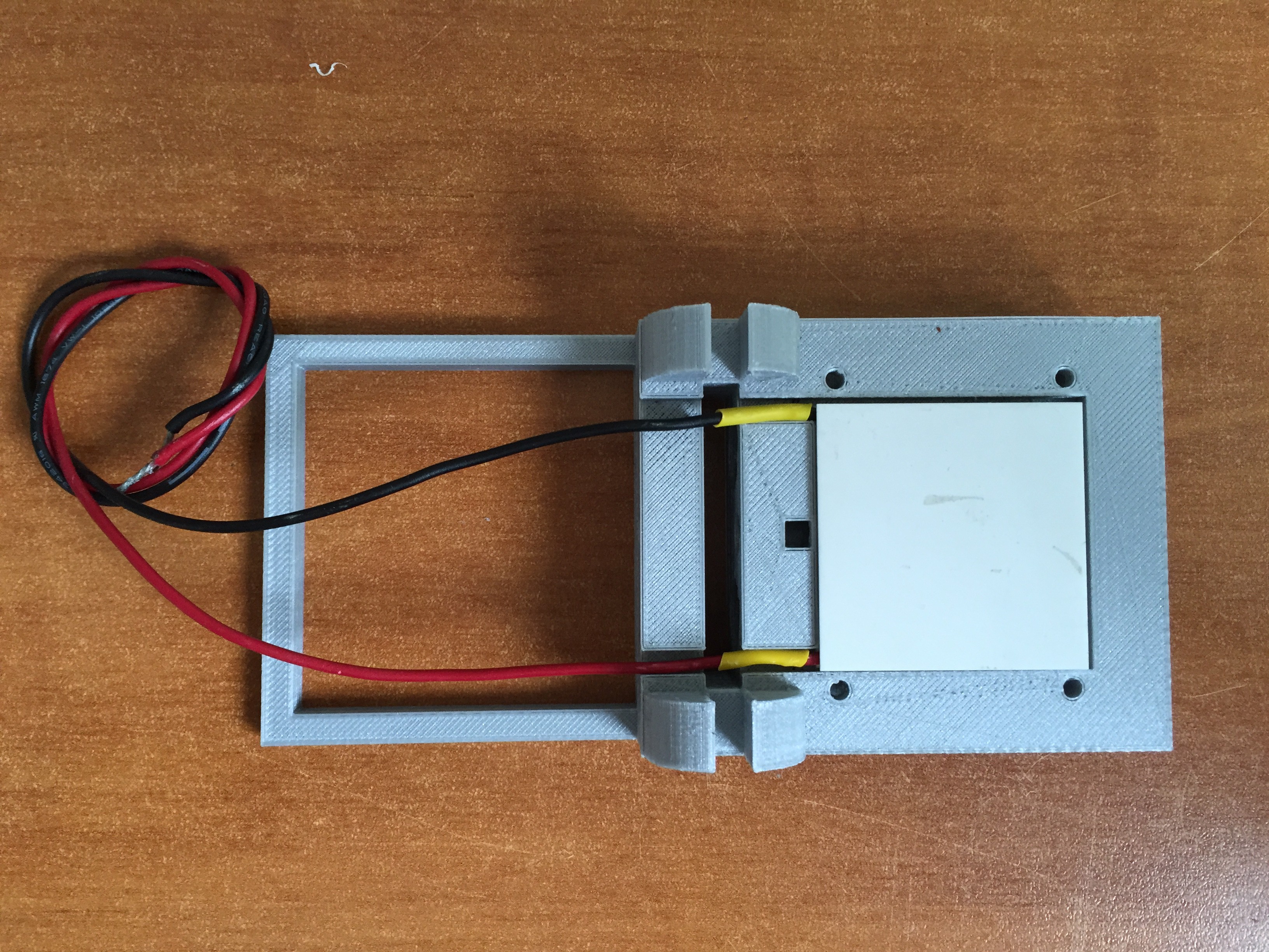
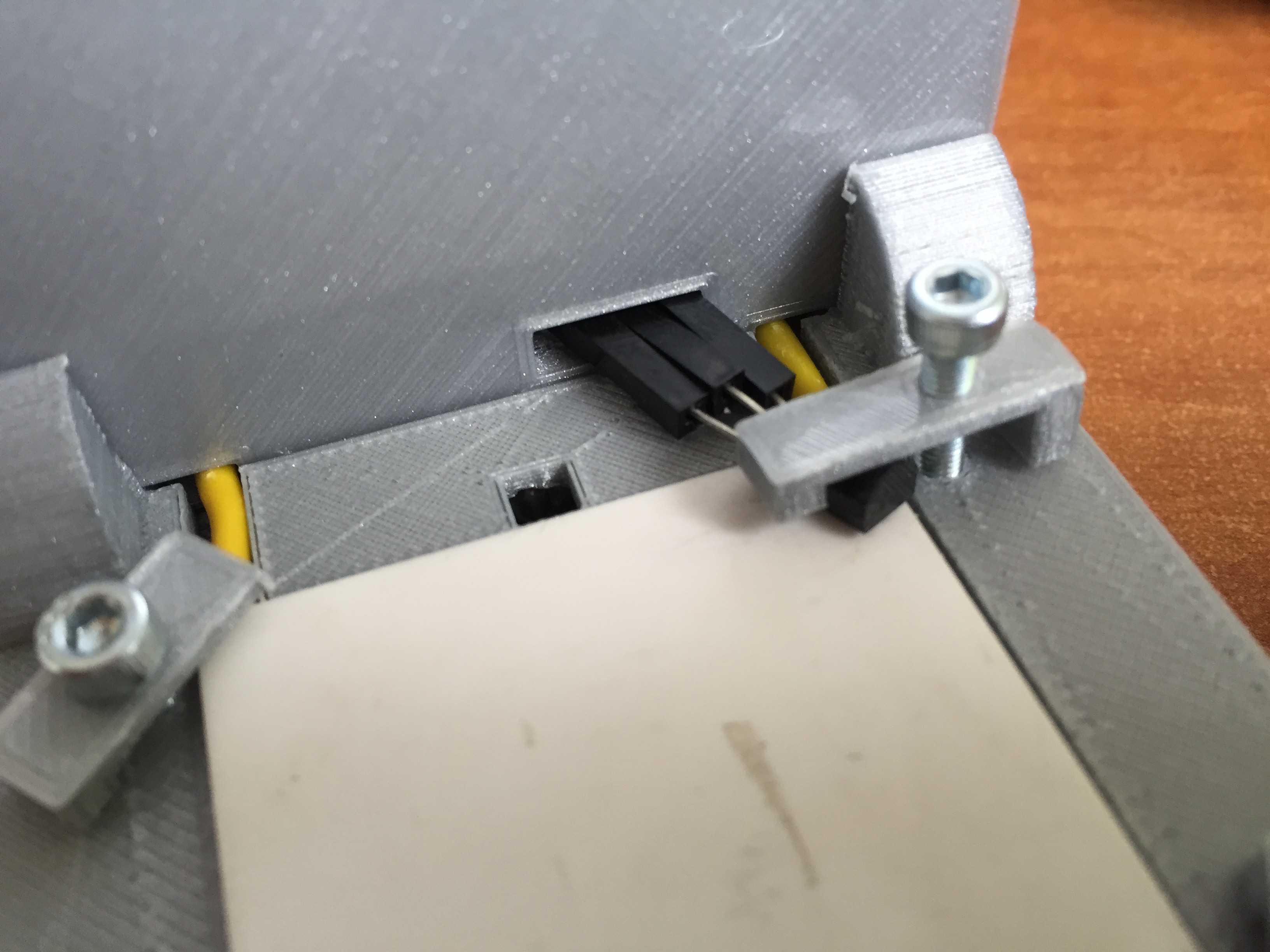
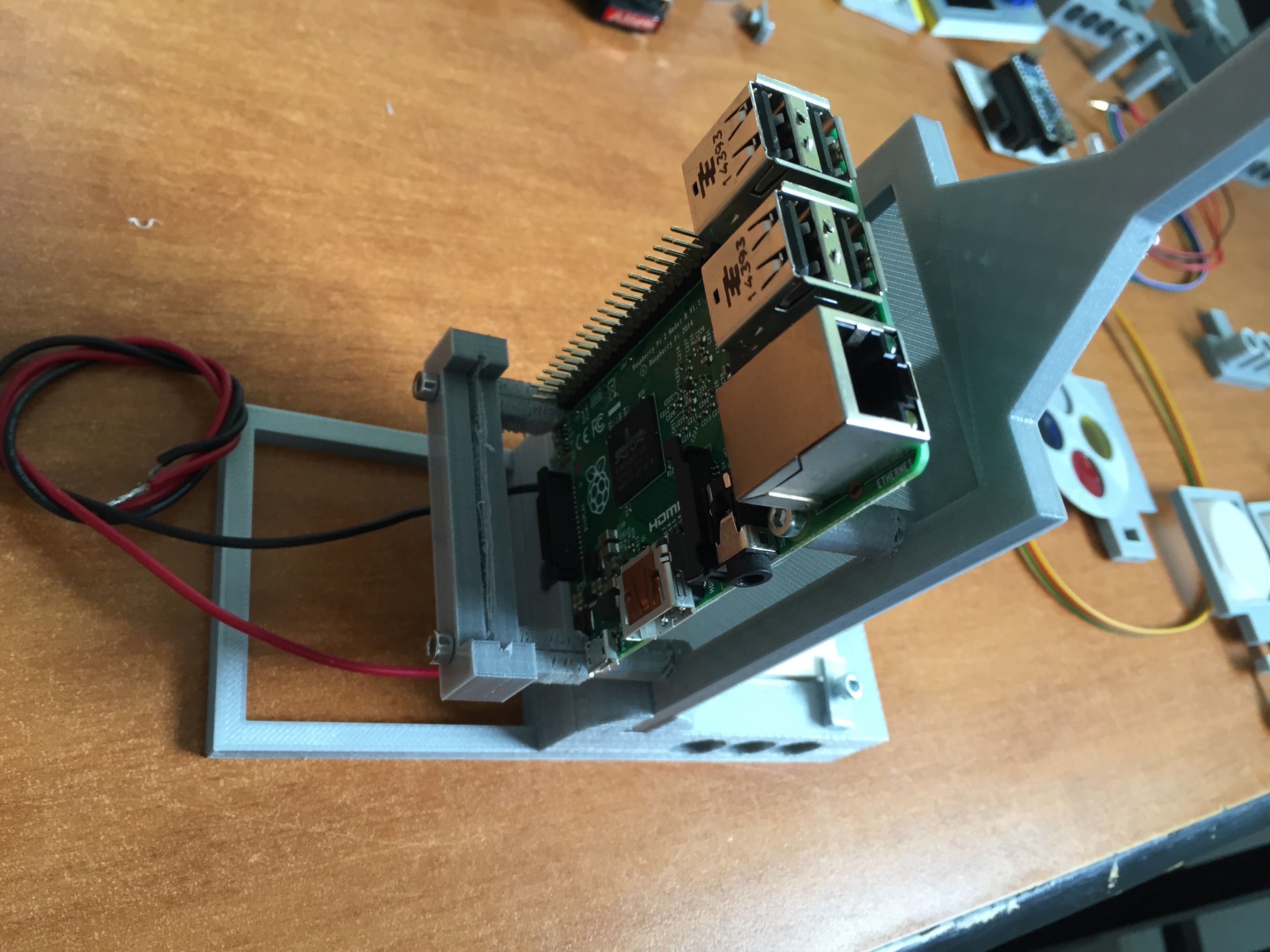
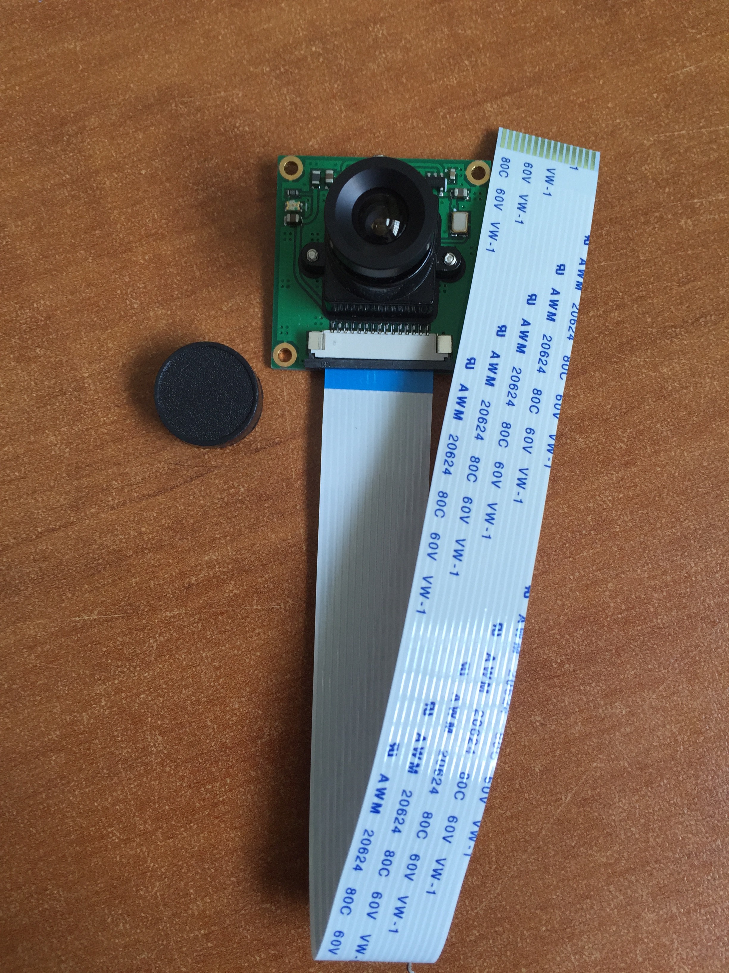
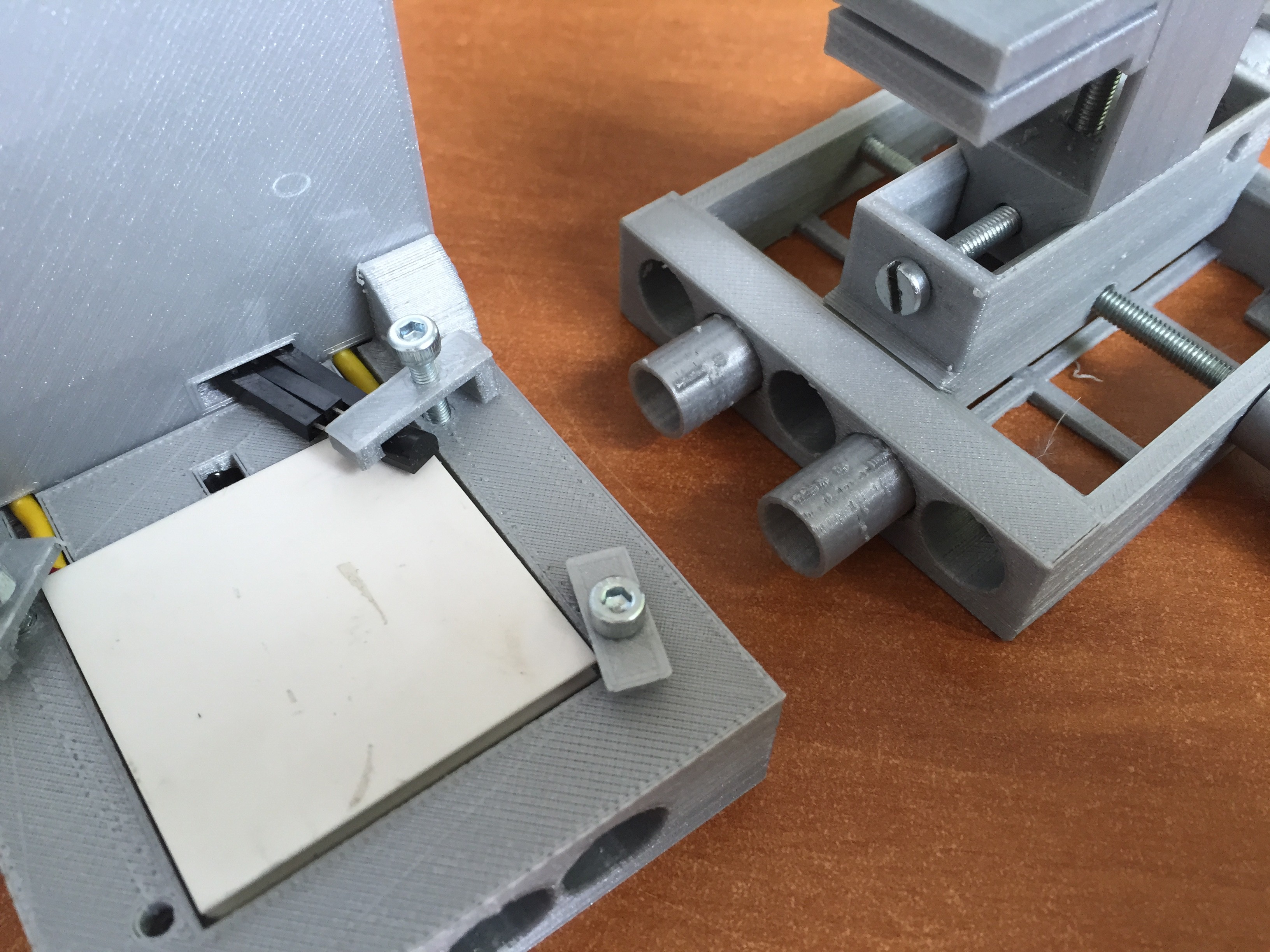
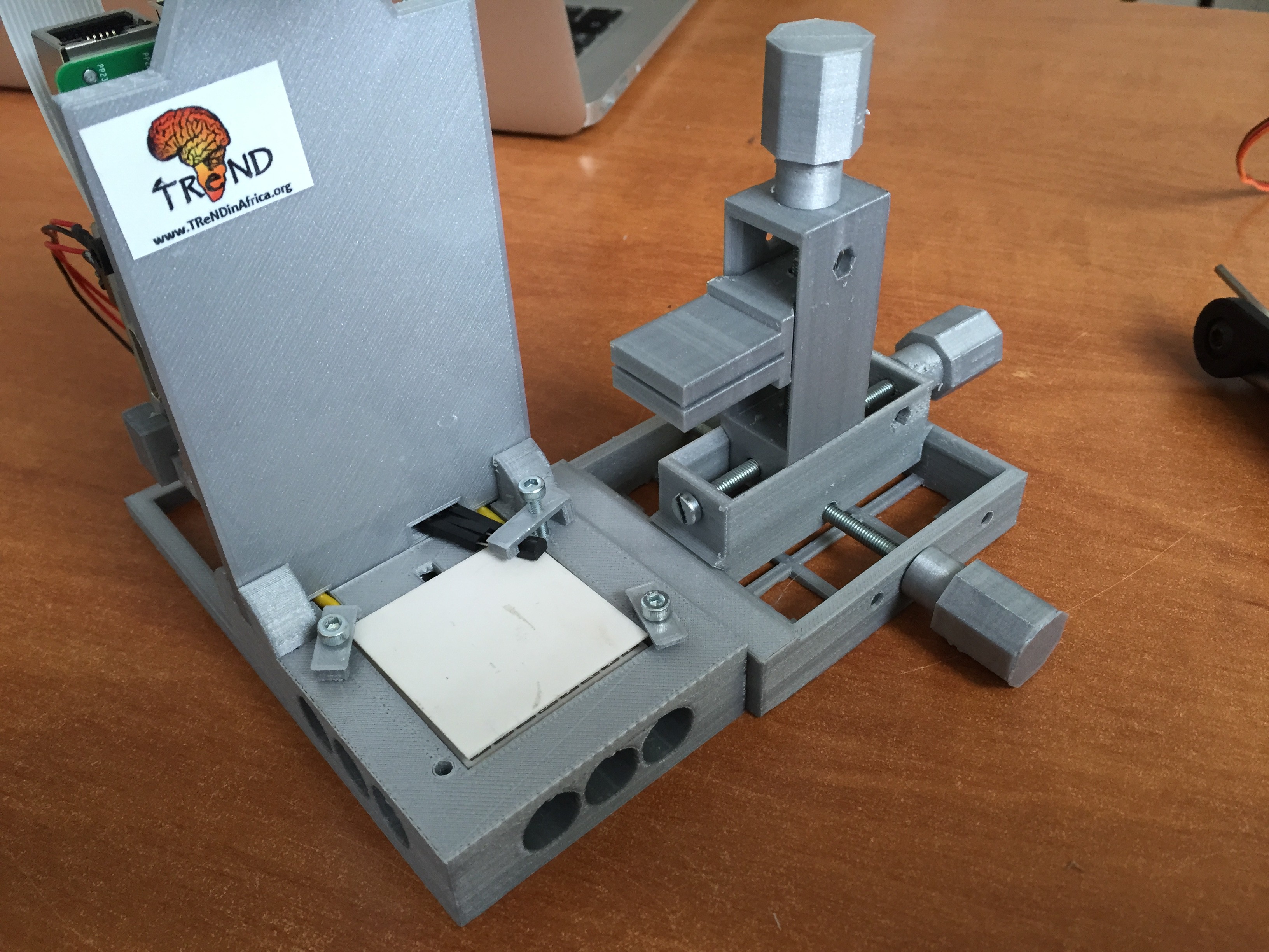
1 - Main body + Raspberry Pi + Peltier n thermistor + Camera
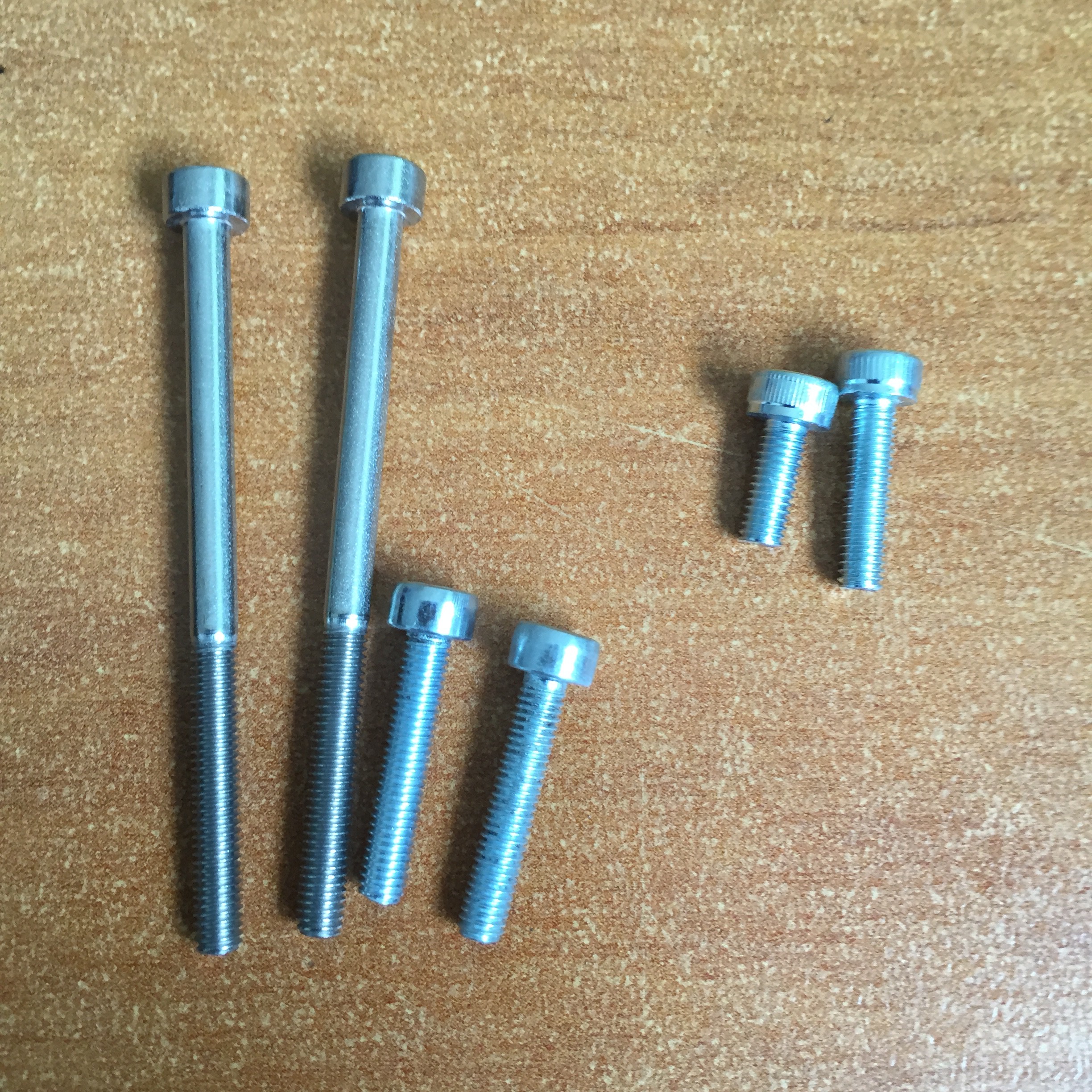
We used Hexagon M3 screws to attach the electronics to the printed parts.
![]()
![]()
![]()
![]()
![]()
![]()
![]()
![]()
The next image shows an earlier version of the PCB, but with the new one, the attachment works the same way:
![]()
![]()
![]()
![]()
![]()
-
6Step 6
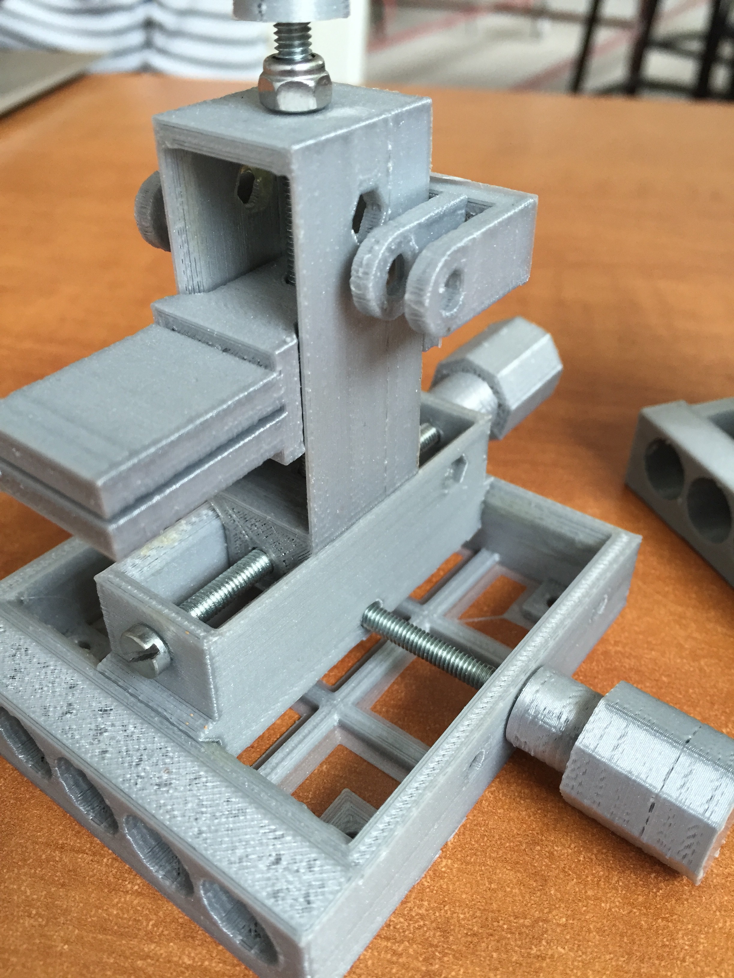
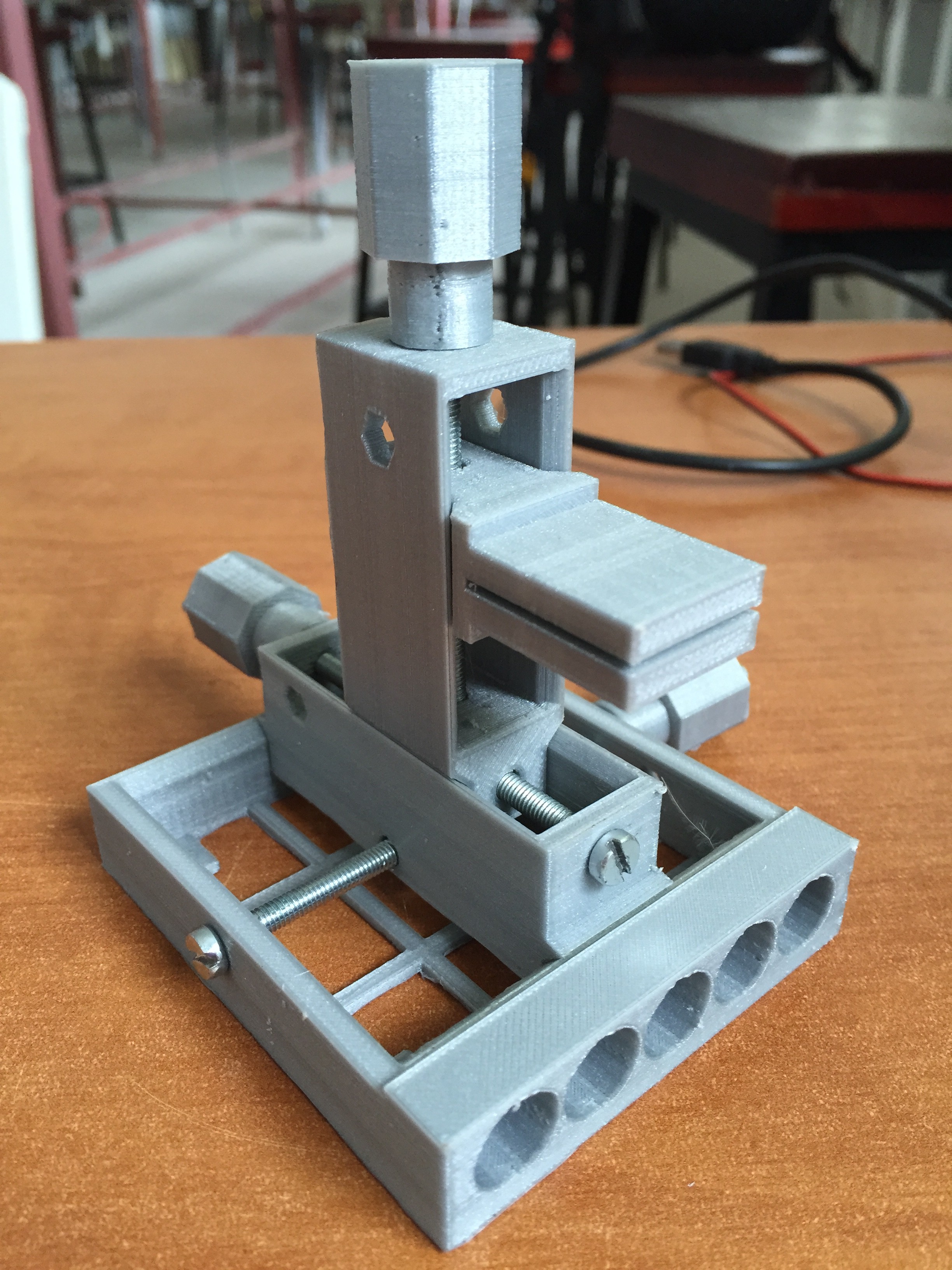
Micromanipulator:
The micromanipulator was added to this project, but it was actually developed before the FlyPi for other purposes (check the repository for it here)
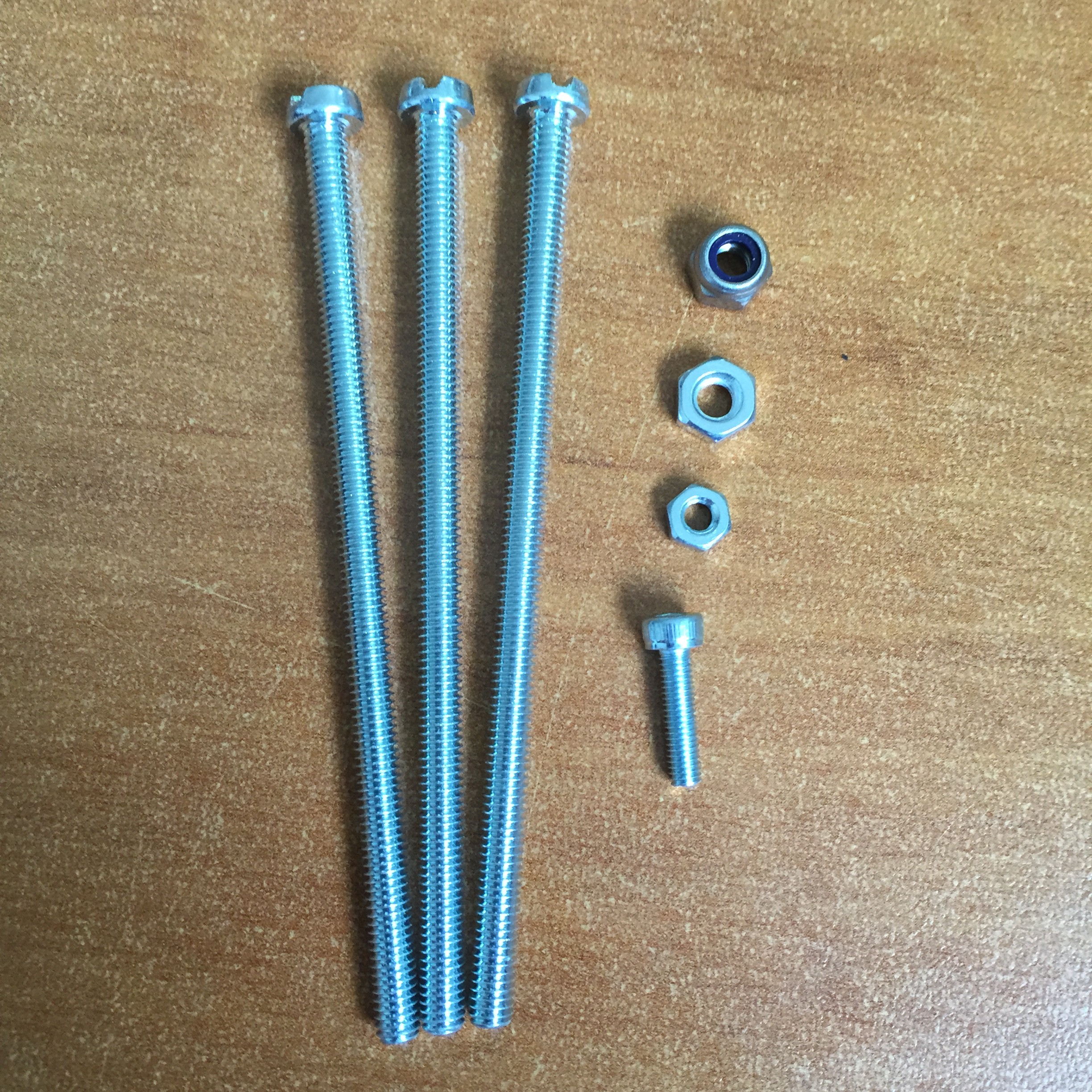
Building it is simple as well. One needs M4 screws and nuts (with and without lock). Two 70mm long and one 100mm long. The nuts shoud be placed on the nuts pockets and the screws threaded through the holes.
![]()
![]()
![]()
![]()
![]()
-
7Step 7
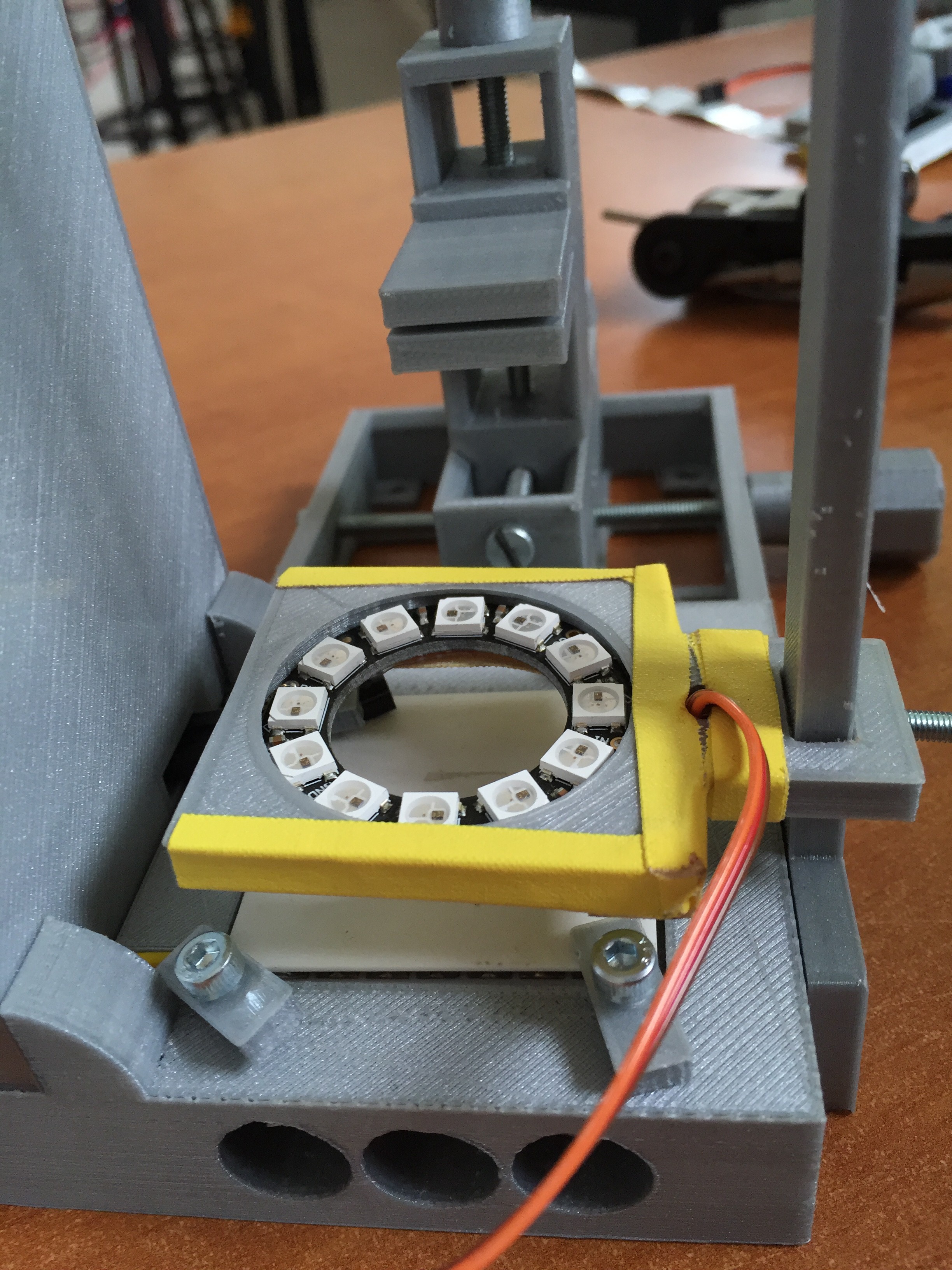
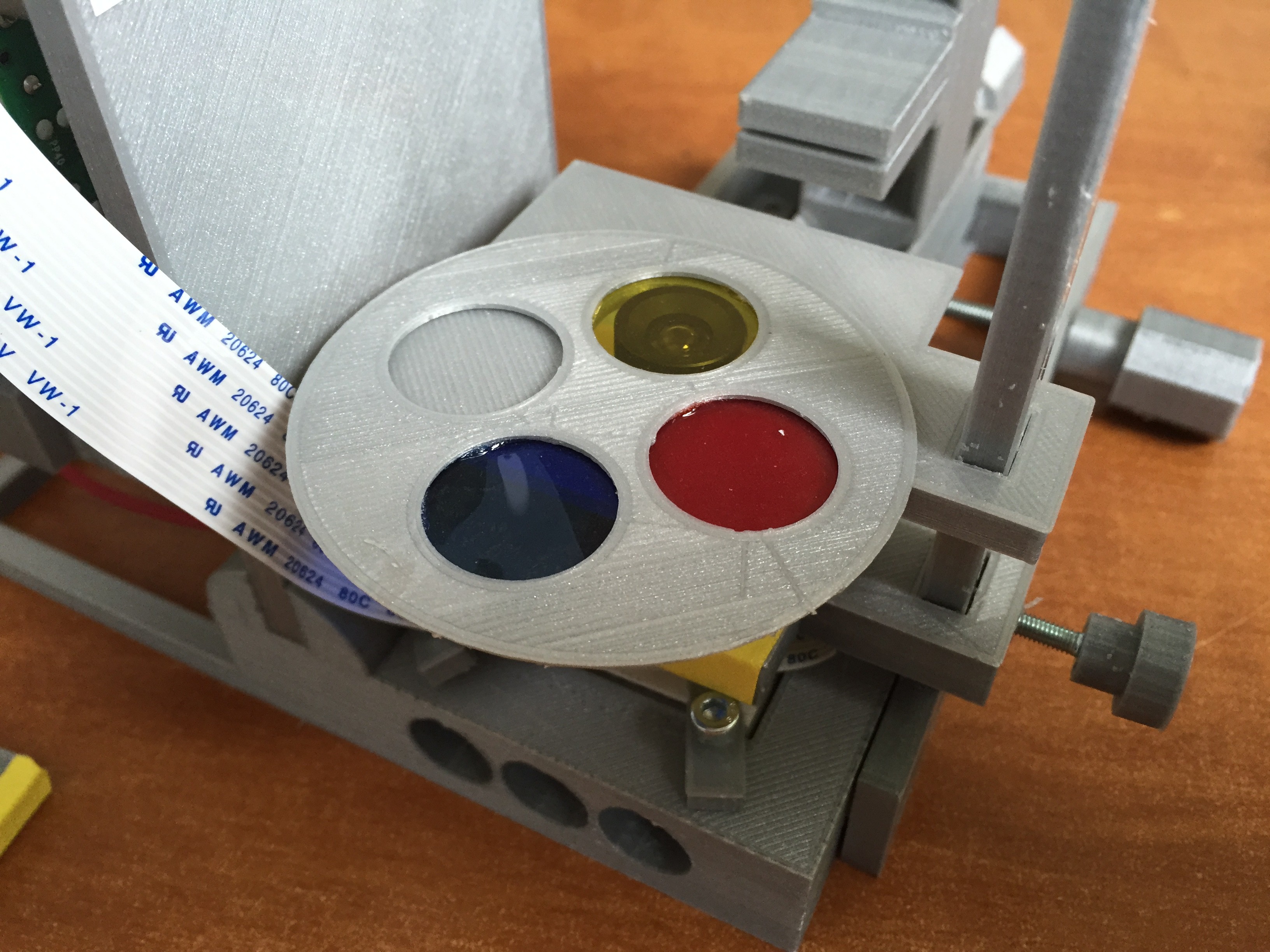
LED ring and light diffuser:
M3 screw, thumb screw adapter, ring holder and Adafruit 12 LED ring.
![]()
![]()
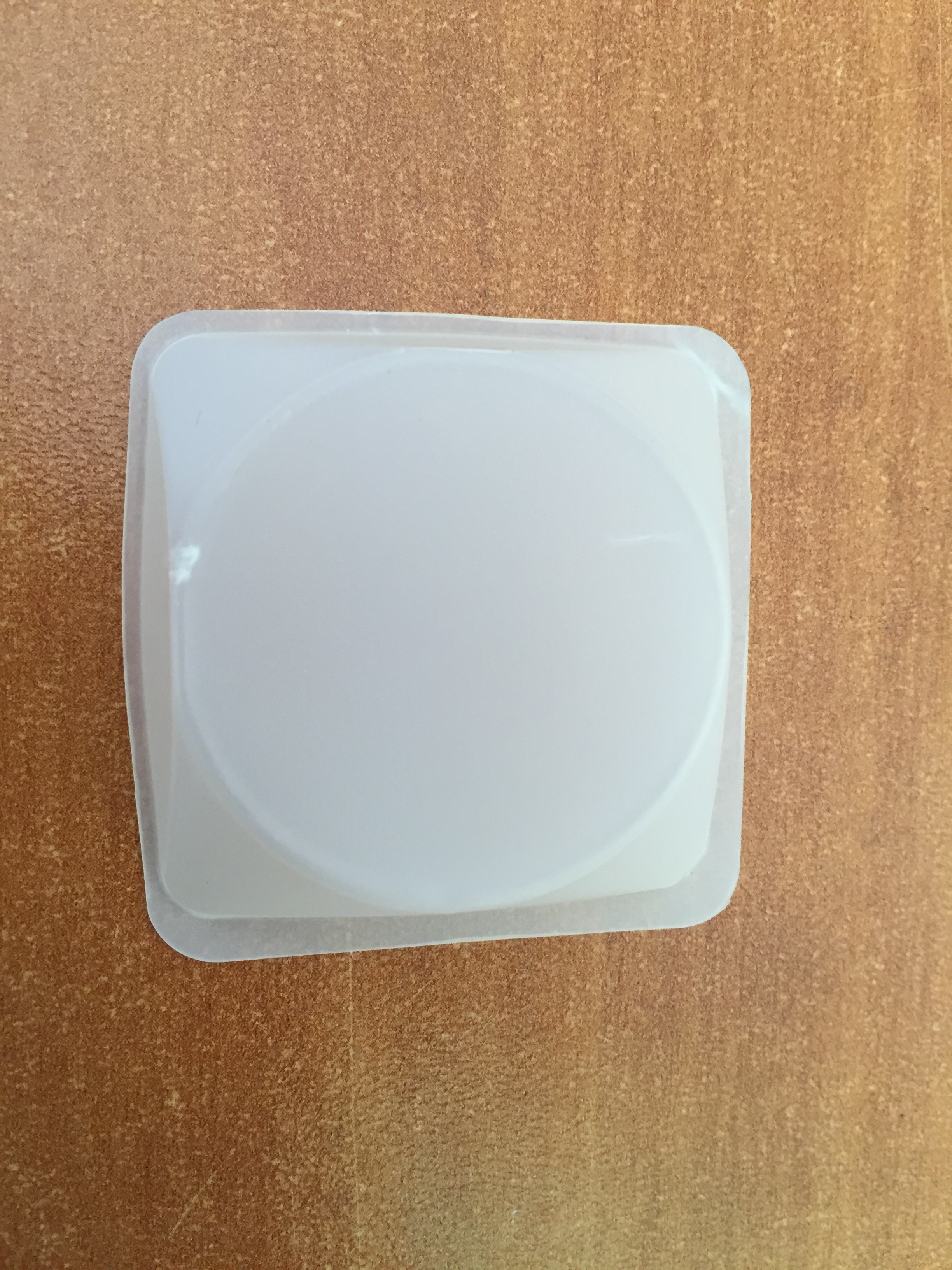
Light diffuser:
In the following images, done with weighing boats, but we have had good experience with 2 paper sheets over one another.
![]()
![]()
![]()
Here there are two light diffusers on top of the LED ring.
![]()
-
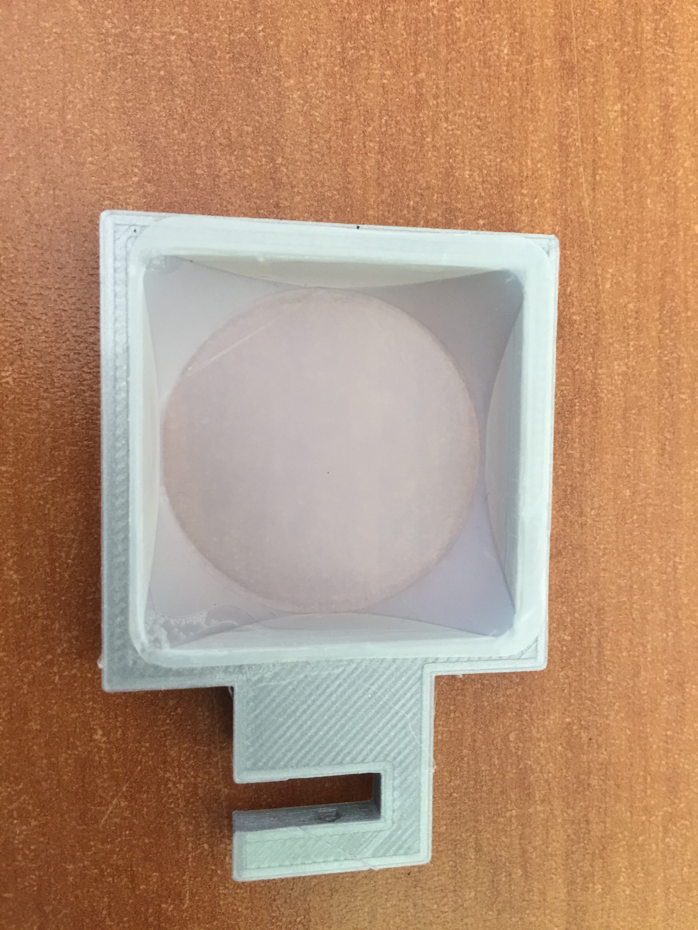
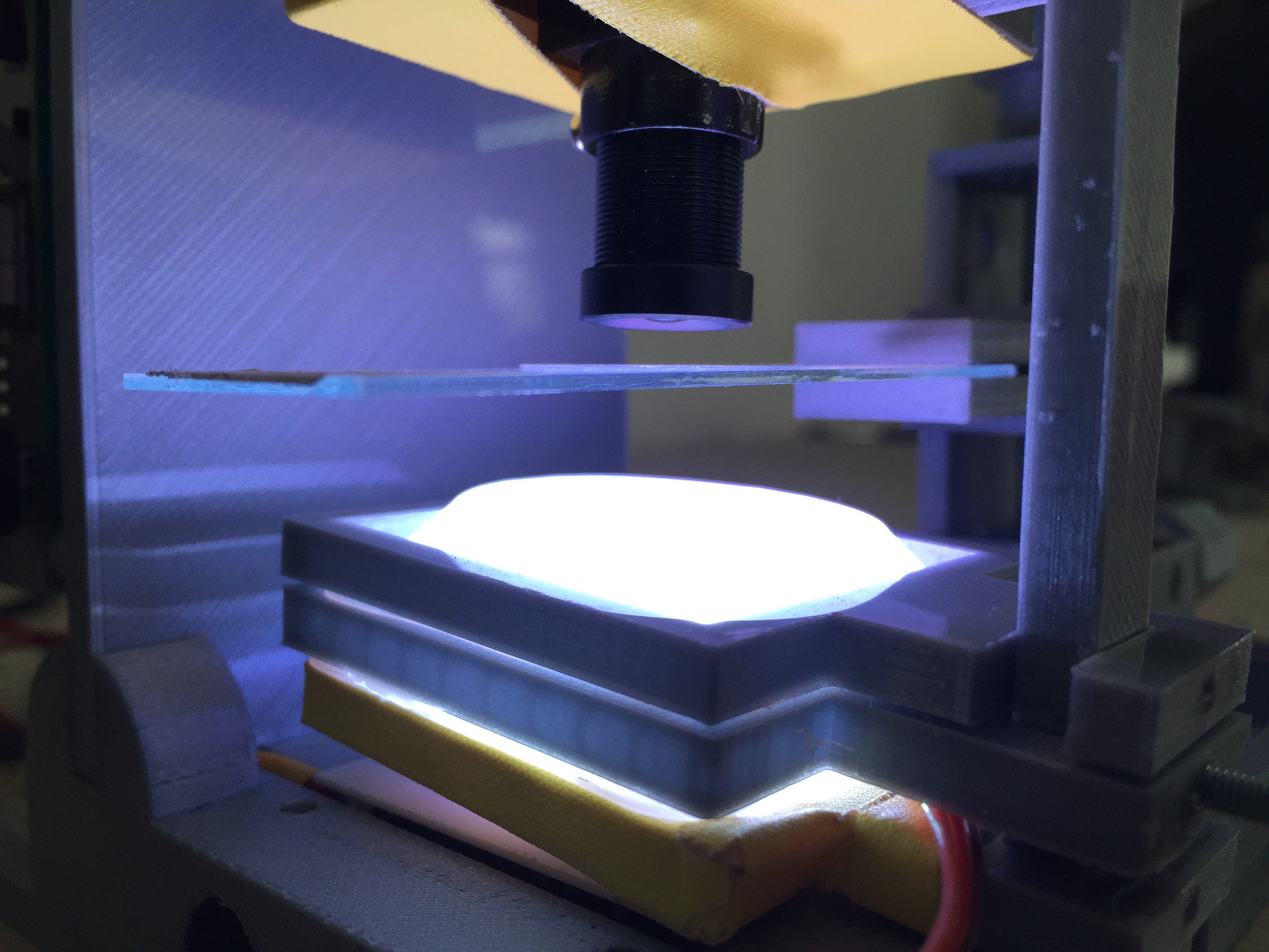
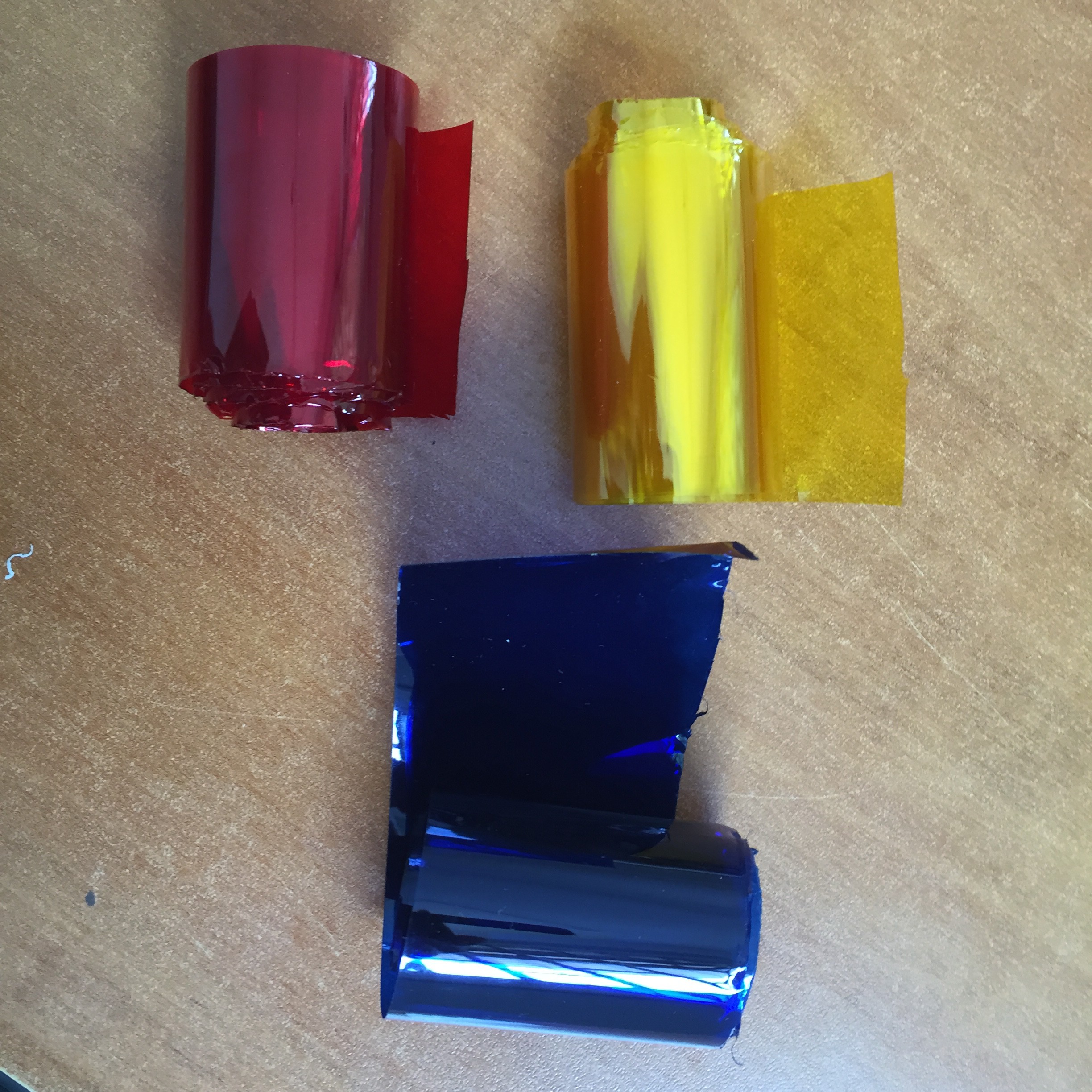
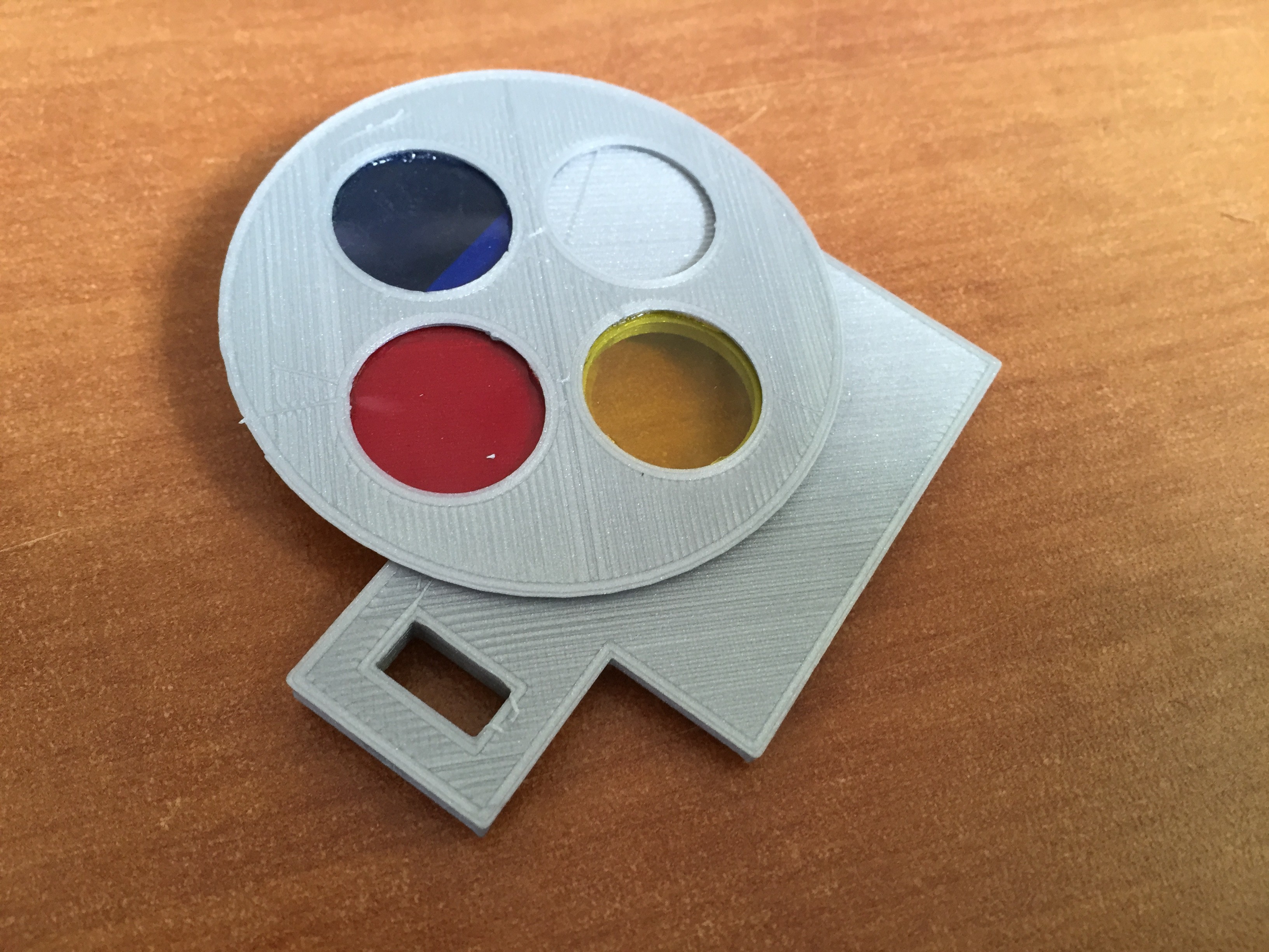
8Step 8
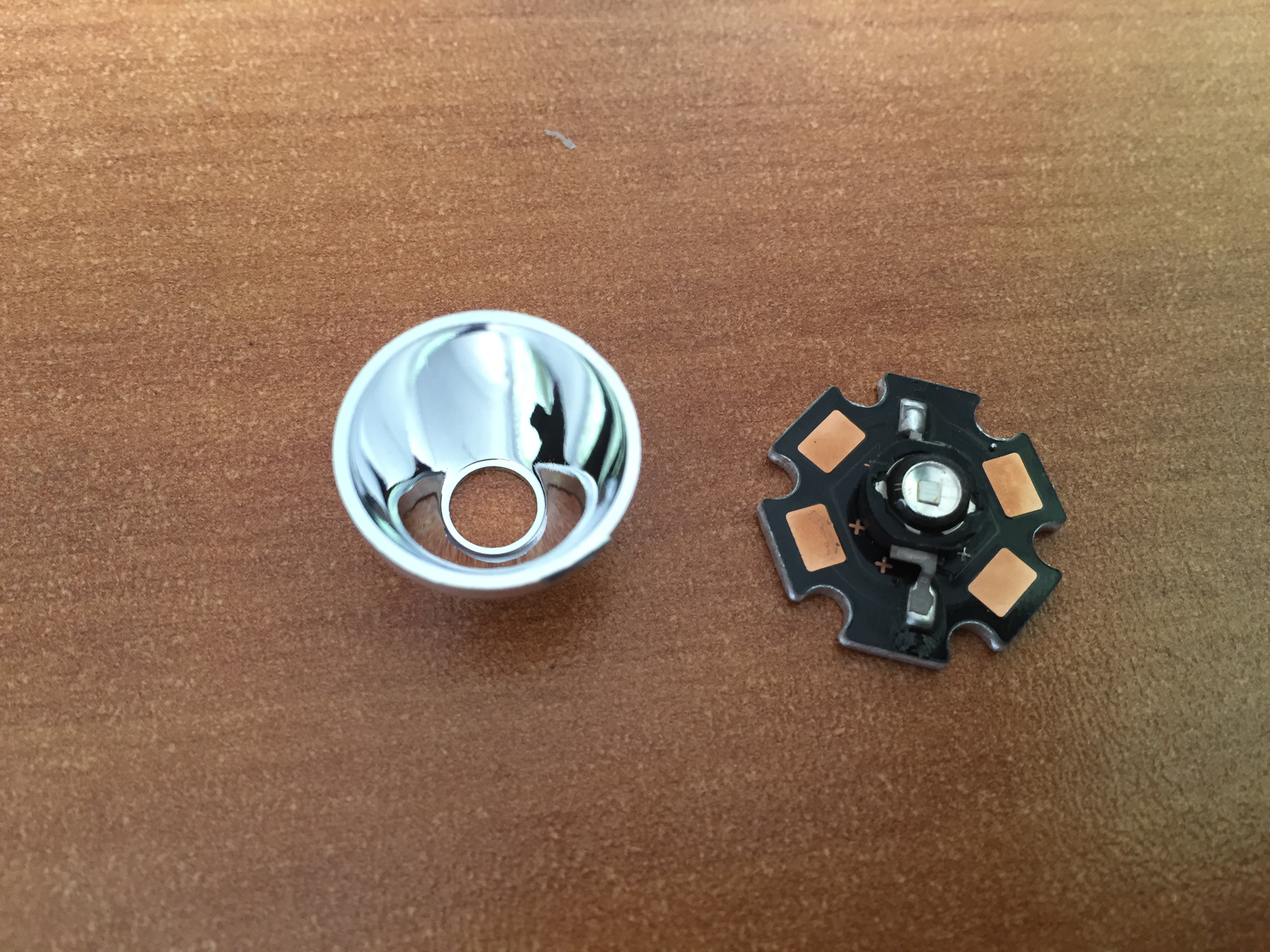
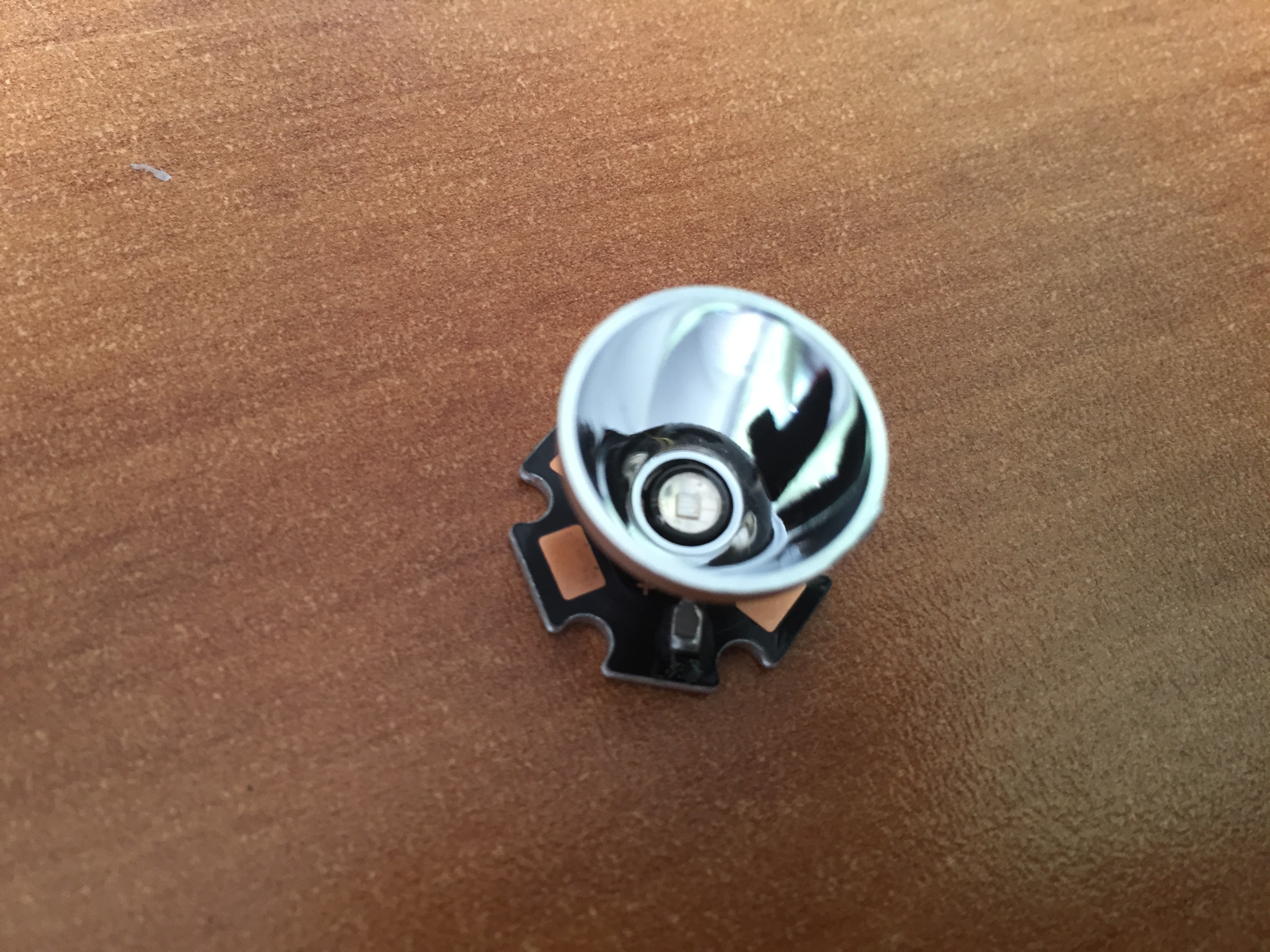
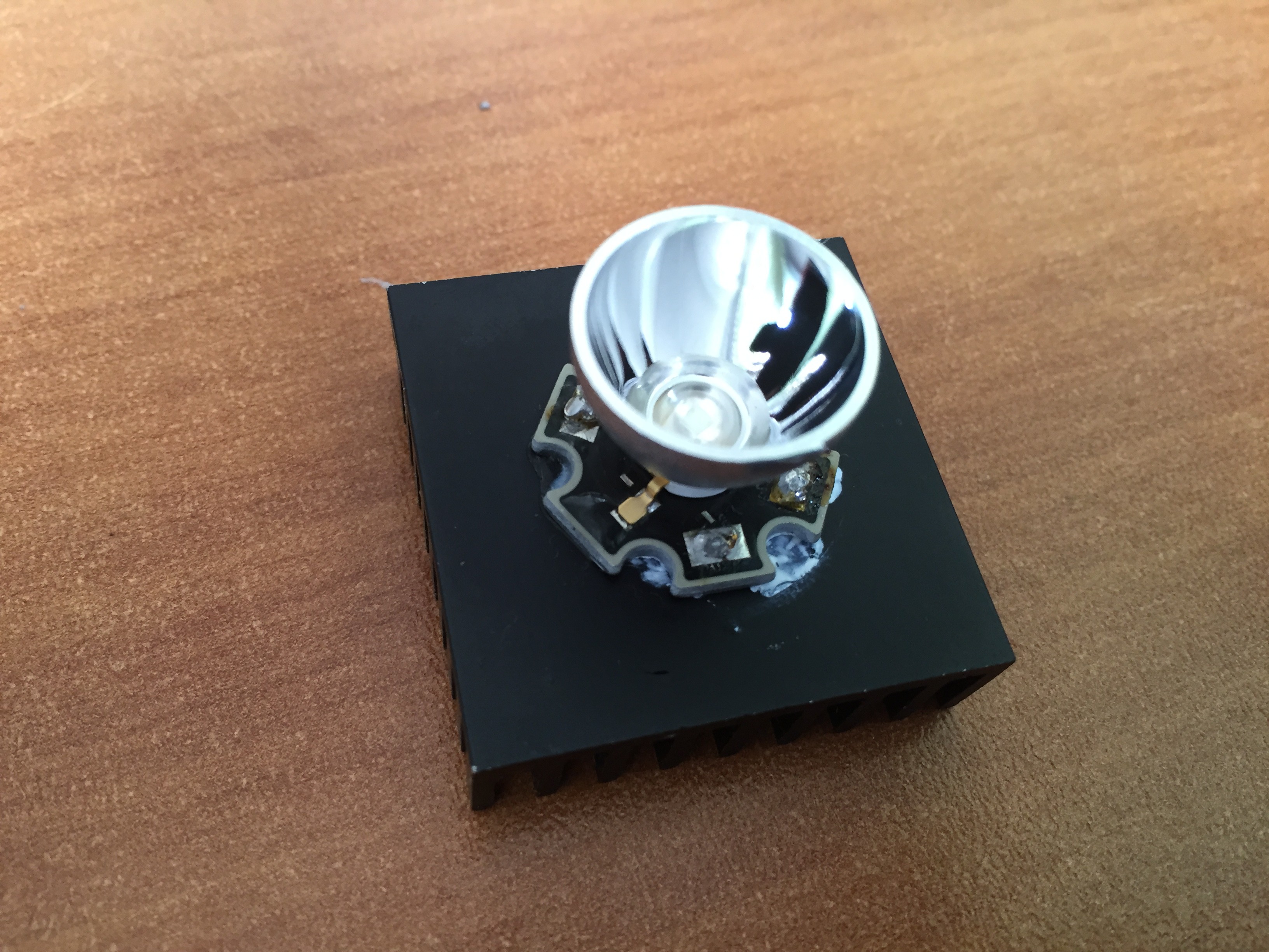
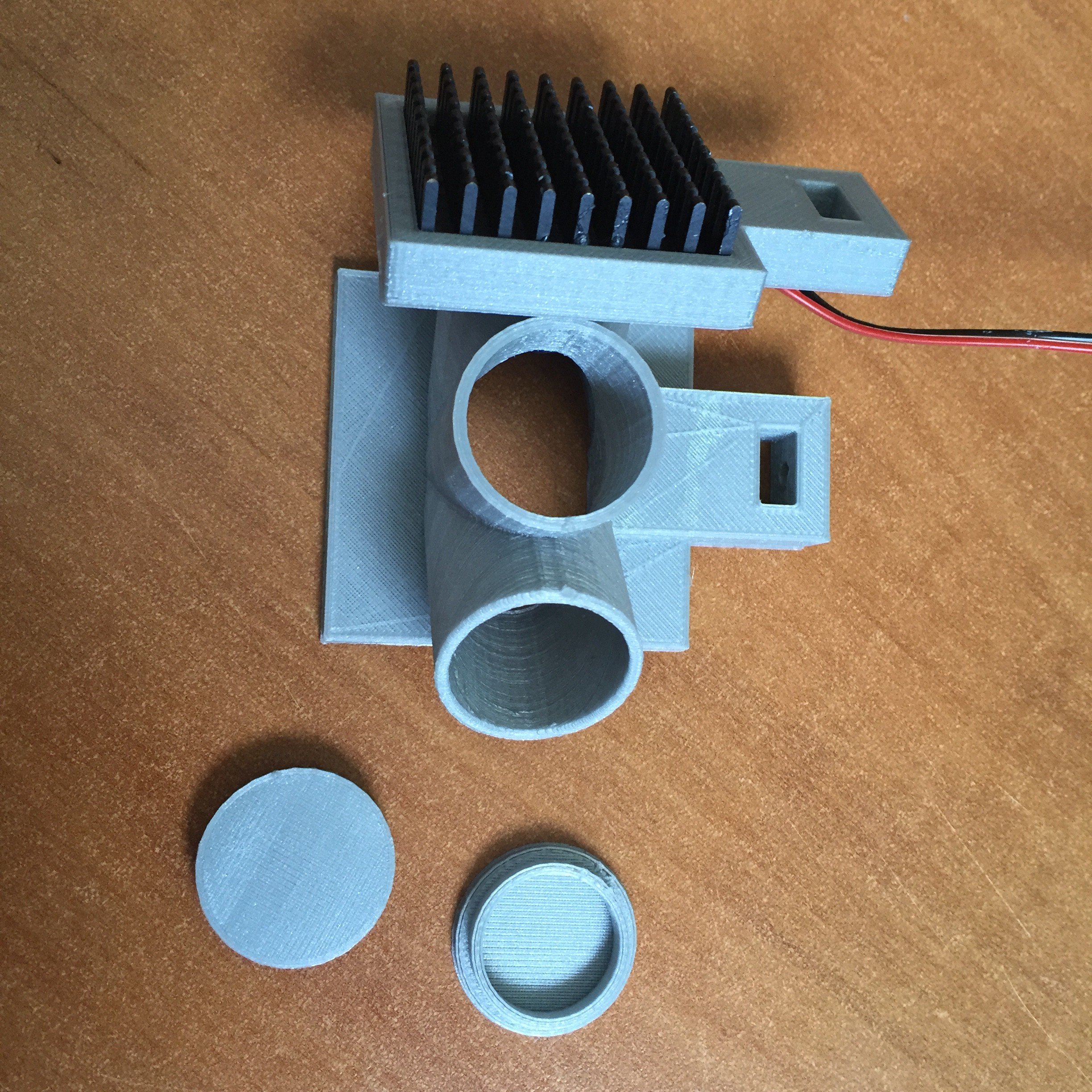
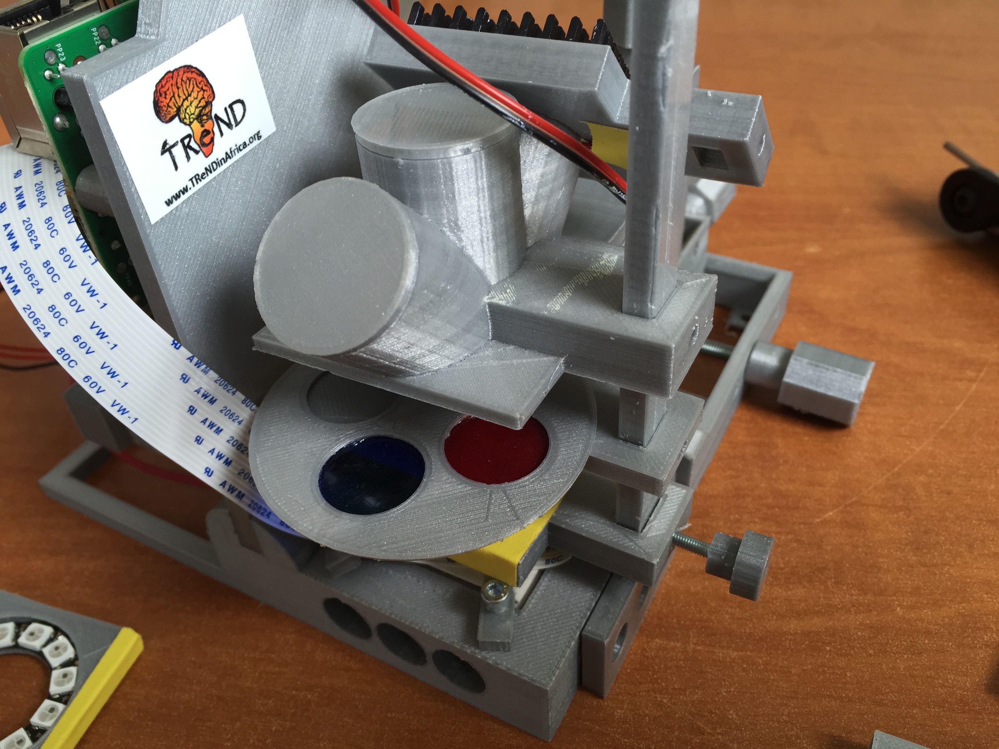
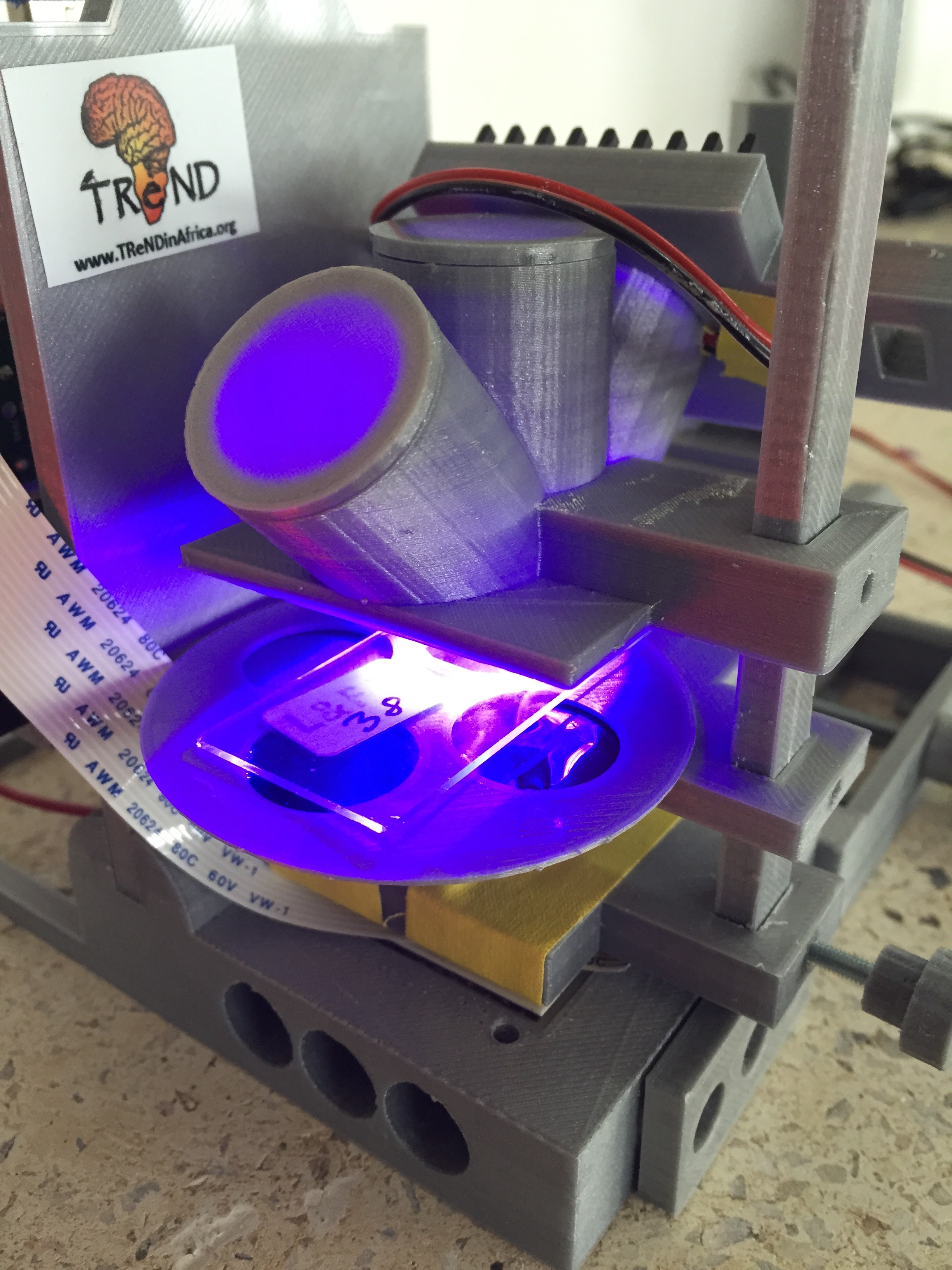
High powered LEDs and fluorescence rig:
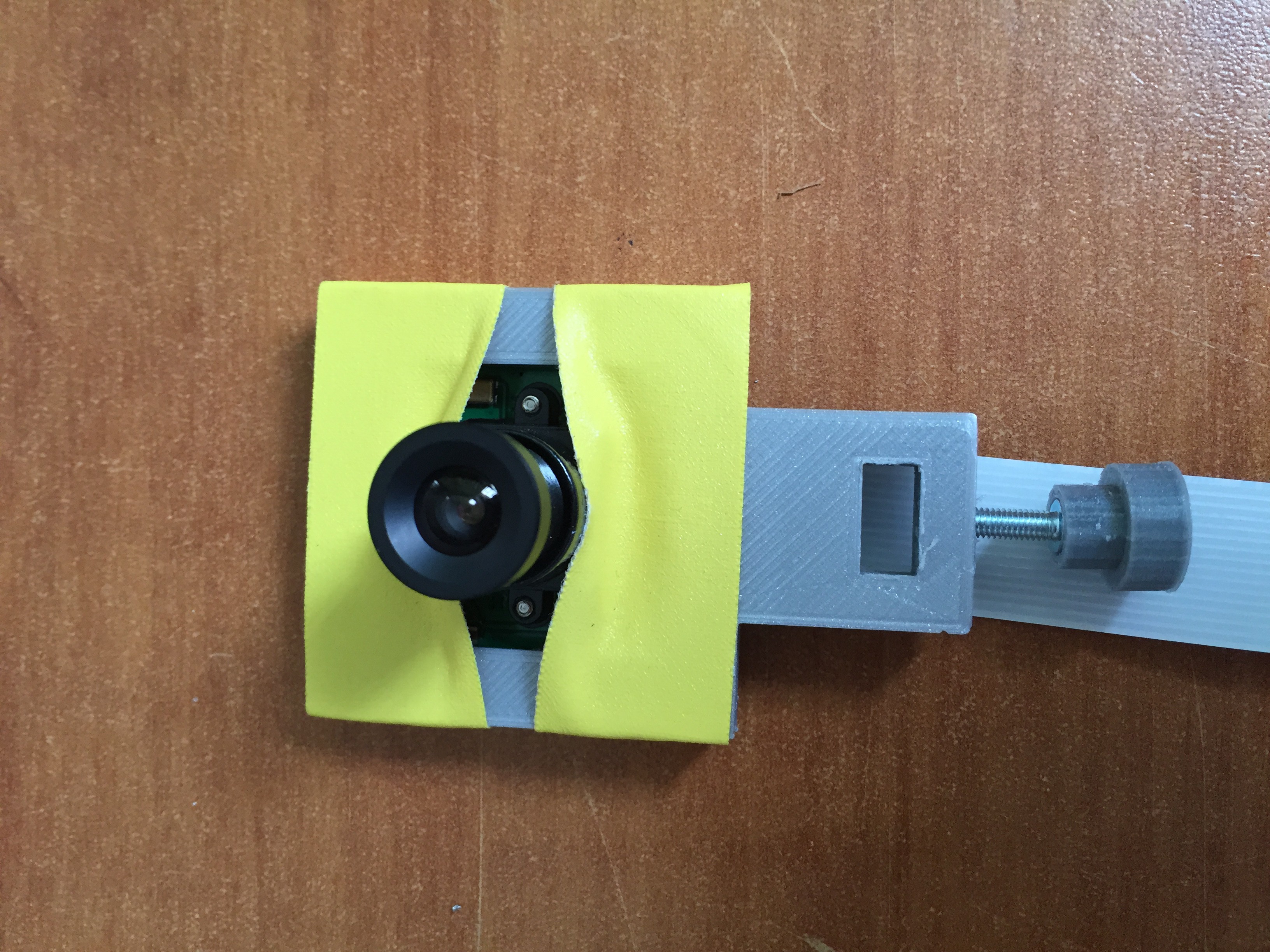
Necessary: 40X40 heat dissipater, Plastic coloured foil (the same ones used in theatre lighting), LED collimator, LED, printed parts
![]()
![]()
![]()
![]()
![]()
![]()
![]()
![]()
![]()
-
9Step 9
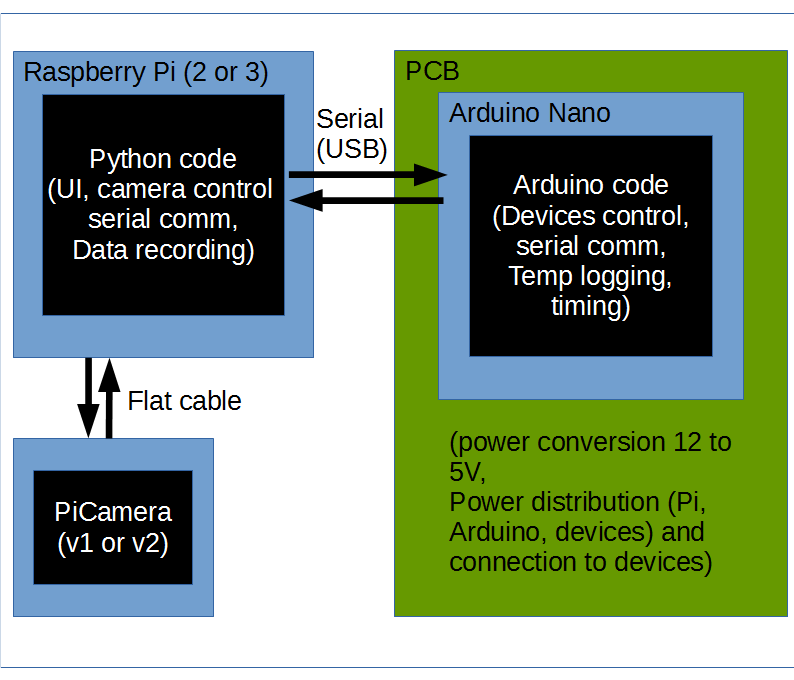
Setting up Arduino and Python code:
The overall schematic for software control can be seen below:
![]()
ARDUINO:
To setup the arduino, the user needs to download the code from the Github repository. Go to the master branch and download the fly_pi_development folder. If the Raspian distribution is up and running, the upload to the board can be done directly from the Pi. Else, any laptop/desktop computer will do. The best way to explain this step is to refer the user to the arduino.cc getting started page
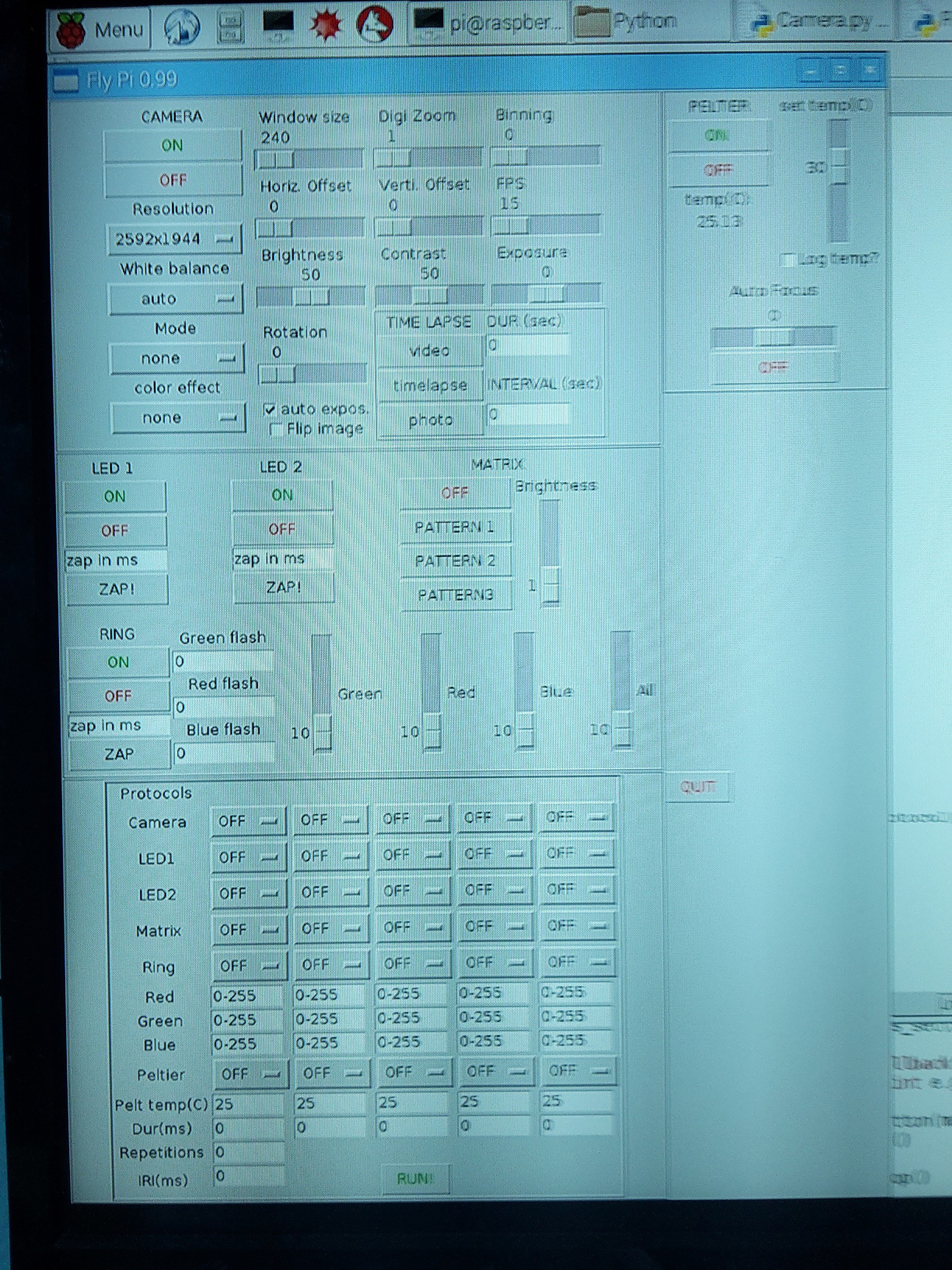
PYTHON UI:
the user interface and control is controlled with custom written Python3 code. It should be downloaded from the github page.
- In the master branch, find the python folder and download all the contents to a folder in the Raspberry Pi desktop.
- Open a terminal and type the following command:
cd /home/pi/Desktop/createdFolder
- Then run a sudo command to run the UI:
sudo python3 ./run.py
This should open the user interface. Make sure that the Arduino is connected via USB to the Raspberry Pi, before running the user interface.
For the curious, below is a scheme of how the python code is arranged (classes and their relations to one another):
![]()
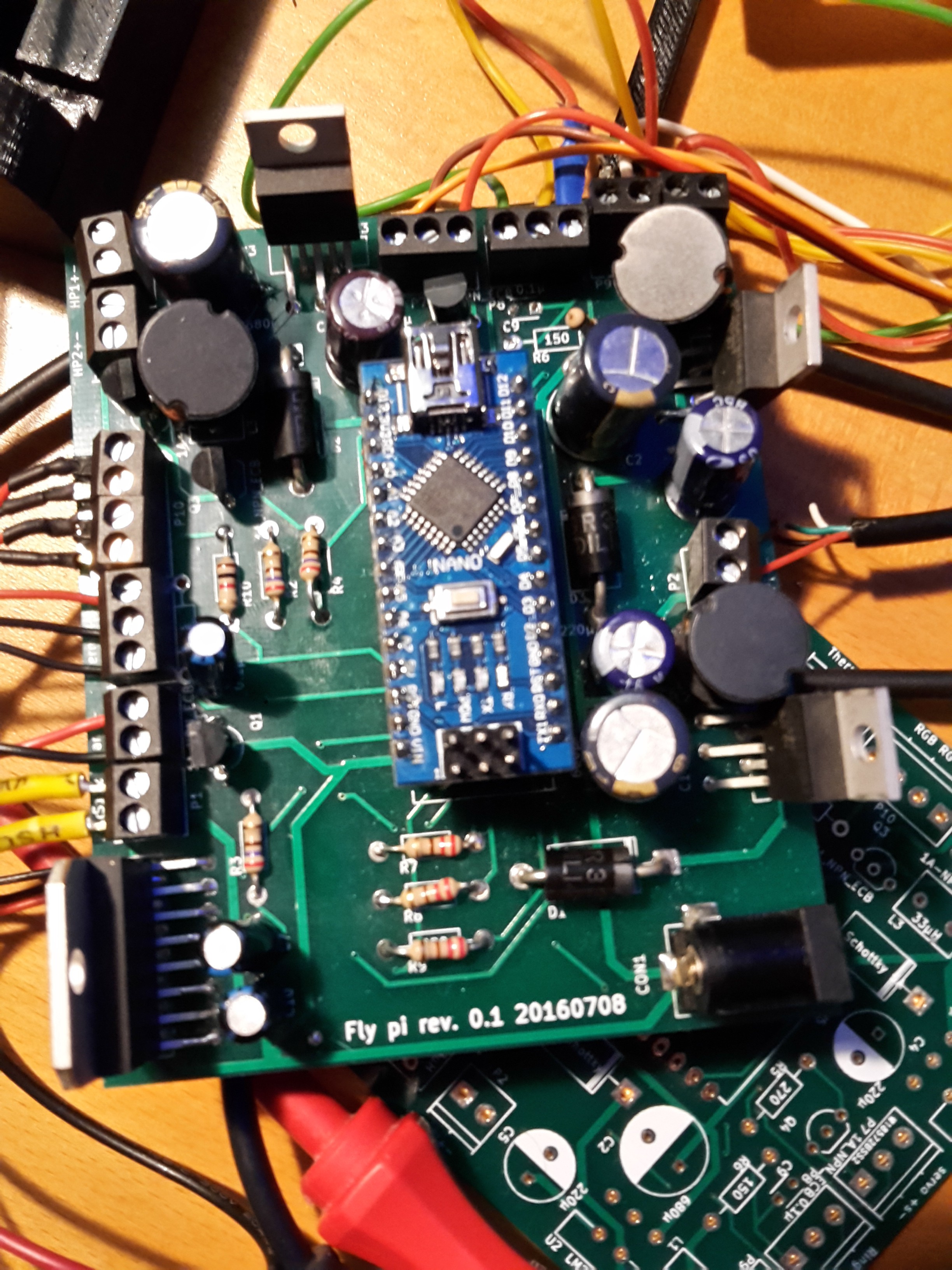
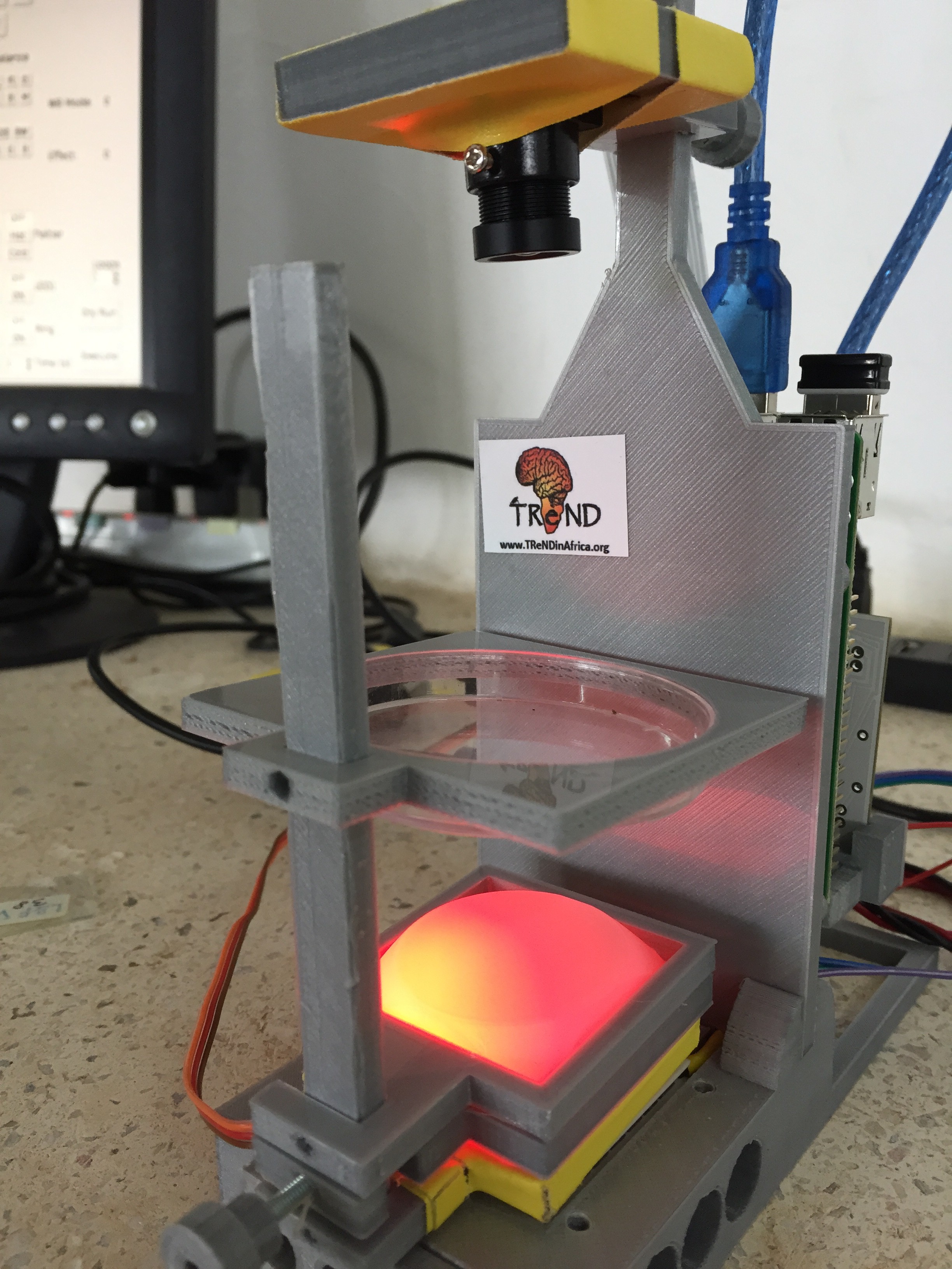
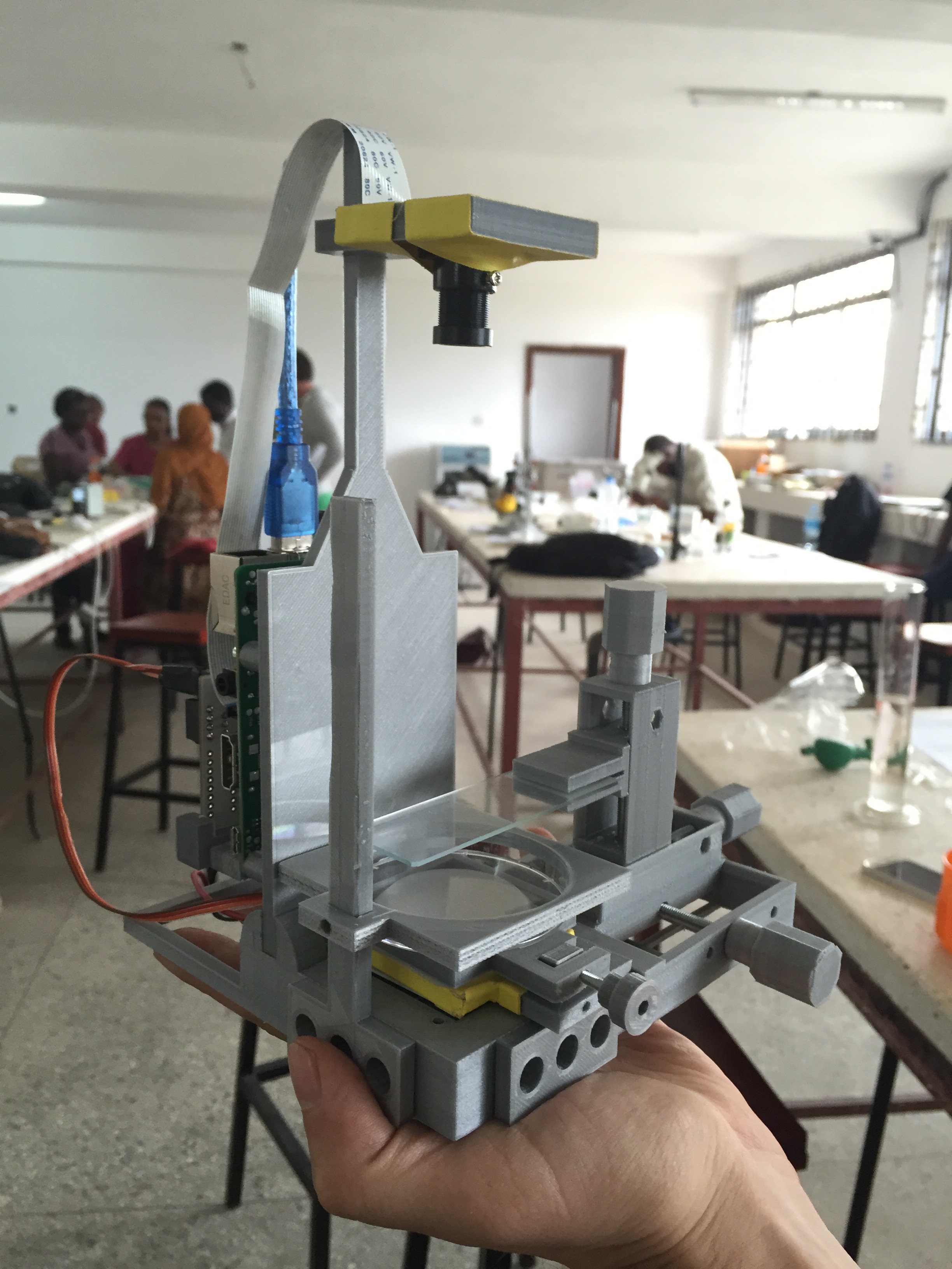
That's it. here is what things should look like if nothing smoked, exploded or melted:
![]()
![]()
Flypi - cheap microscope/experimental setup
Pi + Picamera + M12 lens + Arduino microscope/experimental setup for diagnostics and scientific experiments!


Discussions
Become a Hackaday.io Member
Create an account to leave a comment. Already have an account? Log In.