Andre Maia Chagas
-
Pre print is out!
06/05/2017 at 05:00 • 0 commentsAfter some time in the lab, we finally got around and wrote a manuscript about the FlyPi. It can be found at BioRxiv: http://bit.ly/flypi
It includes a throughout description of the experiments we made, and we contextualize the uses we made of this device. Also it contains an updated assembly and user manual. From Raspberry installation to GUI use.
-
AVI conversion, Protocols
12/05/2016 at 15:12 • 0 commentsNot much to disclose here other than we updated the code and the following things were updated/created:
"TO AVI" button created --> This allows the user to convert the videos recorded by the PiCamera into AVI format, which is preferred over the default h264 as it can be opened by different analysis software, as ImageJ
The camera horizontal and vertical offset now default to the middle of the image when a zoom bigger than 1 is used
The protocol class has been updated. Users can now create their own protocols and have the FlyPi recording data for (hopefully) any amount of time.
-
Overall schematics
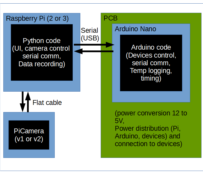
10/05/2016 at 09:03 • 0 commentsTo clarify a couple of things, such as the PCB arrangement, how the Pi and the Arduino communicate, where timing is done, below are a couple of schematics.
Overall schematics: How the Pi, camera, Arduino and PCB are connected to each other and what each part is doing.
![Overall view - How Pi, camera, Arduino and PCB are connected and their roles]()
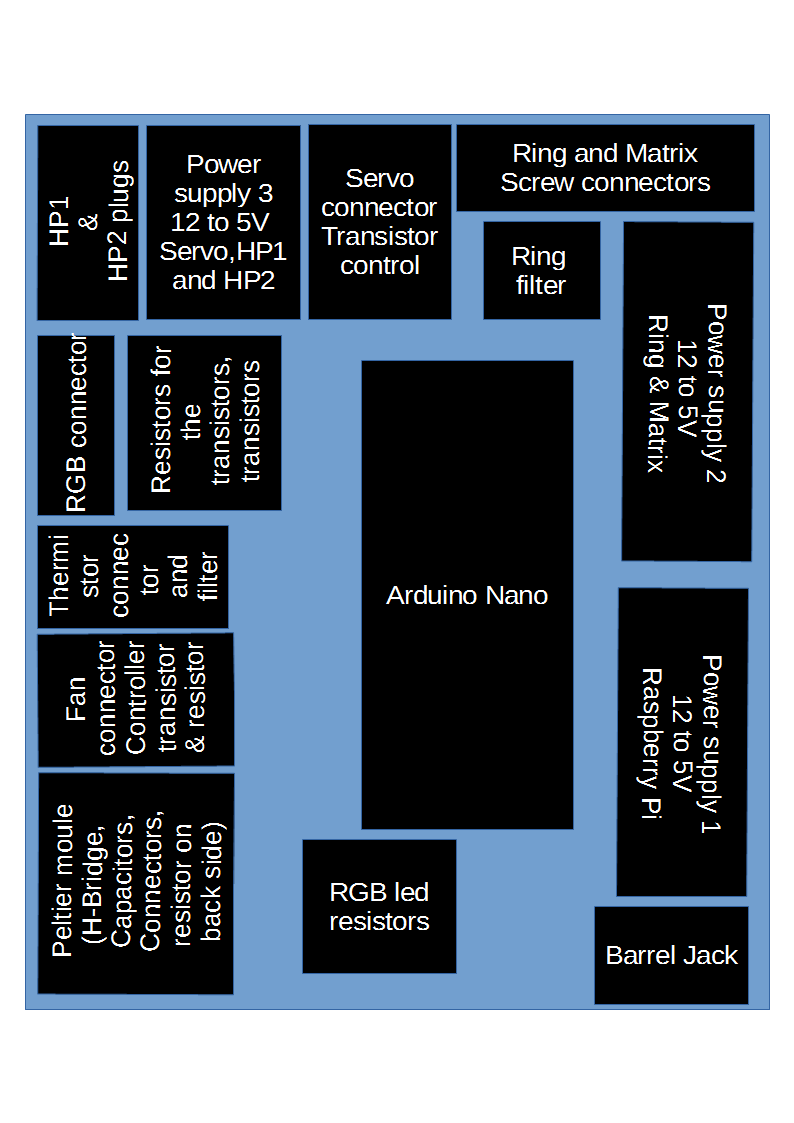
PCB schematic, how components are distributed on the PCB according to location and functional module
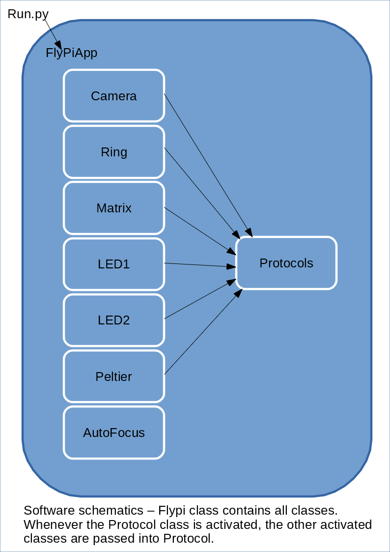
![PCB Layout by region/functional units]() Python software schematic: How the different independent classes relate to each other
Python software schematic: How the different independent classes relate to each other![]()
-
Some UI demos and tests
07/11/2016 at 05:55 • 0 commentsHere is a small collection of videos demonstrating the new user interface and some of the functionalities implemented for each component:
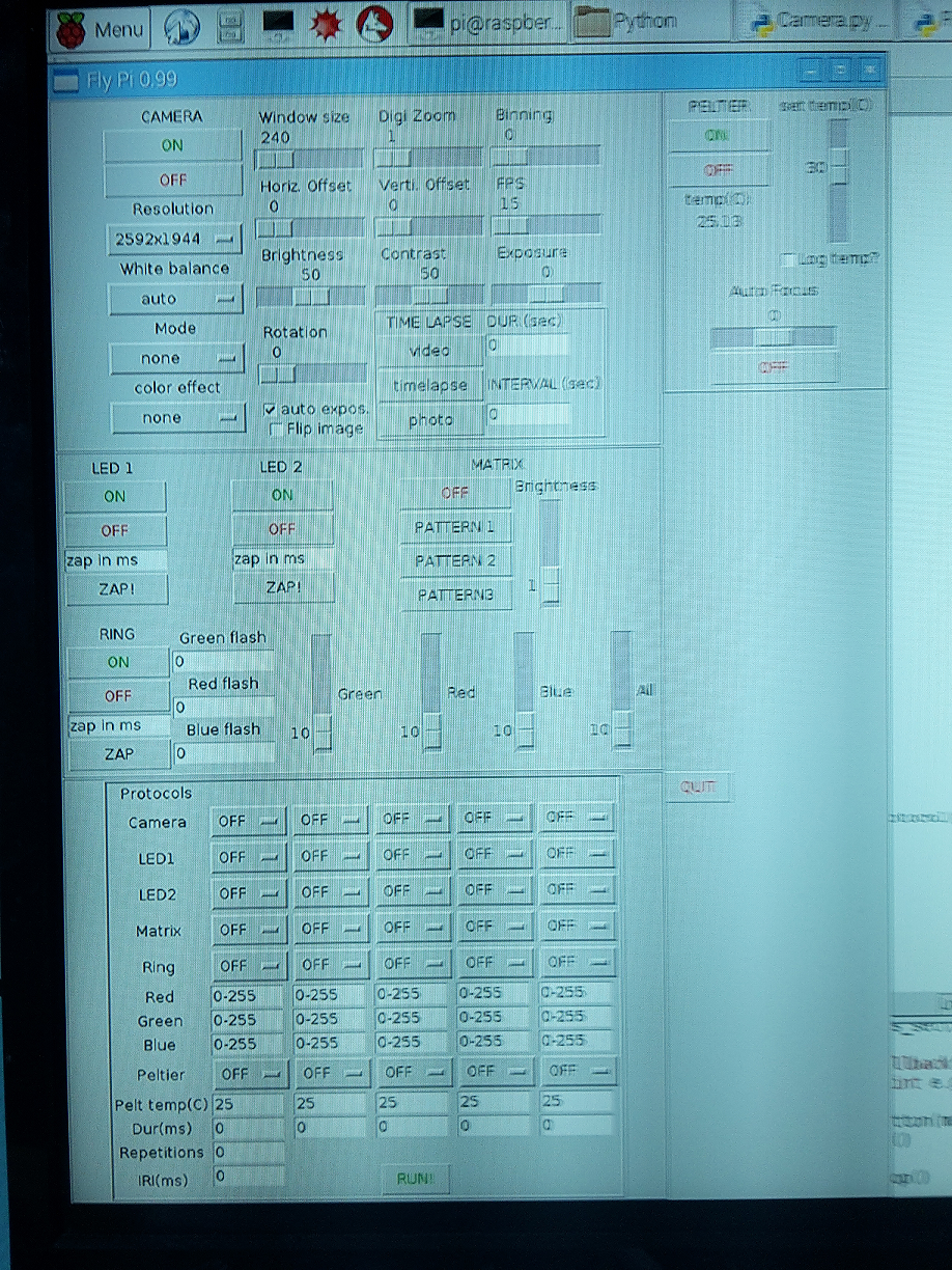
And a screenshot of the soon to be finished "Protocol class", which can be used to automatize tasks:
![]()
-
FlyPi distribution licenses
07/11/2016 at 05:36 • 0 commentsAlthough this project is already open to everyone, we have never explicitly stated which license we are using for it's distribution
To keep adherent to the open source philosophy, make this tool as useful and widespread as possible and to hopefully contribute to bringing citizen science and academic science closer together, the FlyPi is distributed as (CC BY-SA 4.0) or the creative commons Attribution-ShareAlike 4.0 International license. Meaning that anyone is allowed to use, distribute, remix, and even commercialize this project, as long as proper reference is made to the creators and the new variants are distributed under the same license.
-
PCB design with KiCad
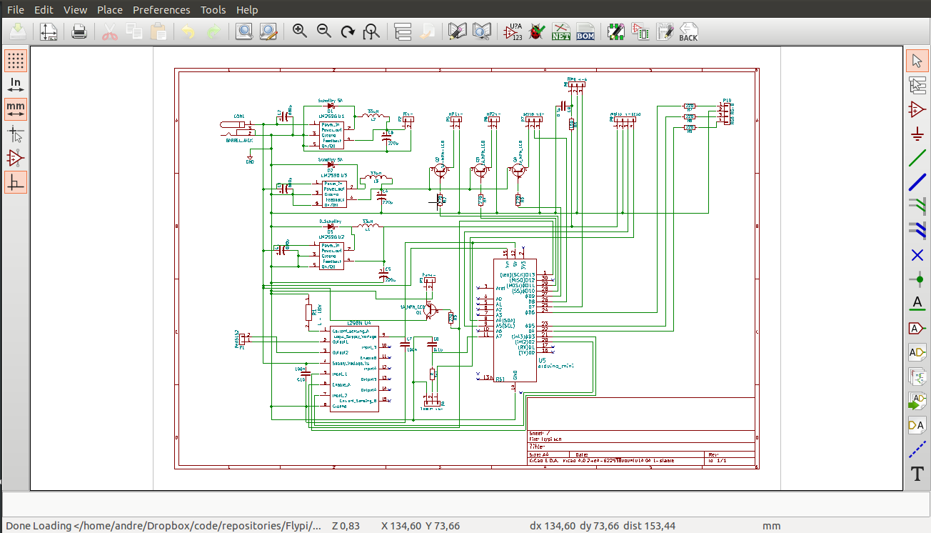
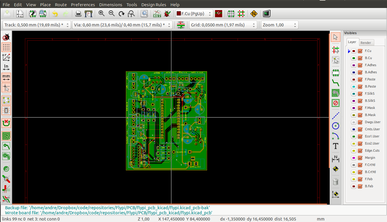
07/08/2016 at 07:04 • 0 commentsWe started the PCB design for this project in Fritzing. Since the project started small and simple, it was a satisfactory solution. As the project grew and became more complex, using Fritzing became too cumbersome. A reported bug had tracks disappearing, which made getting the board correct a freakin' mess. We then decided to migrate to KiCad. If the folks over the CERN use and develop it, how bad could it be?! Turns out it was quite easy to learn it (make sure to install the latest version!) and develop the new board, see the image of the schematics and pcb layout:
![]()
![]()
-
Overview video
06/05/2016 at 19:24 • 0 commentsHere is a small video with an overview of the Flypi. Some user interface shots (although this version is a bit outdated), some shots of the device in action
-
HackadayPrize2016 entry log
05/31/2016 at 19:11 • 0 commentsScientists need to have the proper tools to perform experiments and test their ideas. These tools are expensive, because they normally use cutting edge technology and are produced in "small" quantities by only a handful of companies. This ends up restricting who and where research is being done, which aggravates the situation in a lot of places where simple research could bring a lot of improvement to society.
Our project aims are:
-Development of a cheap (so far a complete set is ~100-150 US$) open source microscopy system capable of
--- Recording photos (time lapse and single snaps) and videos
![]()
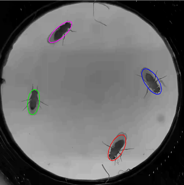
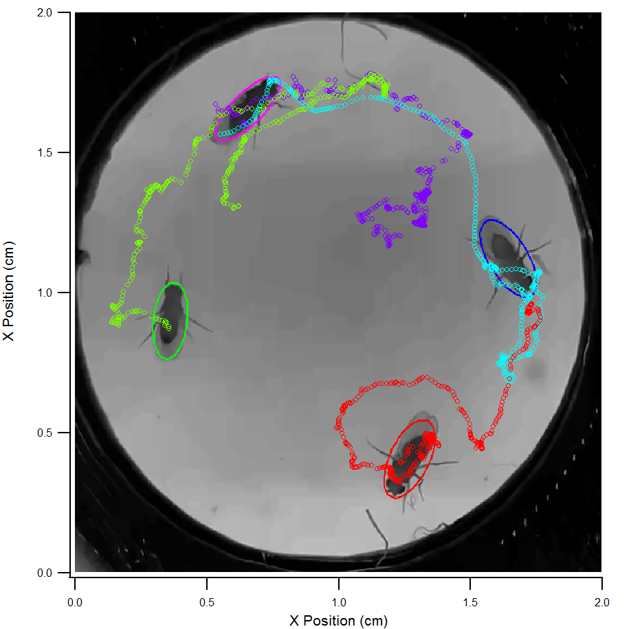
--- Analysis of recorded data (motion tracking, time series of the time lapses)
![]()
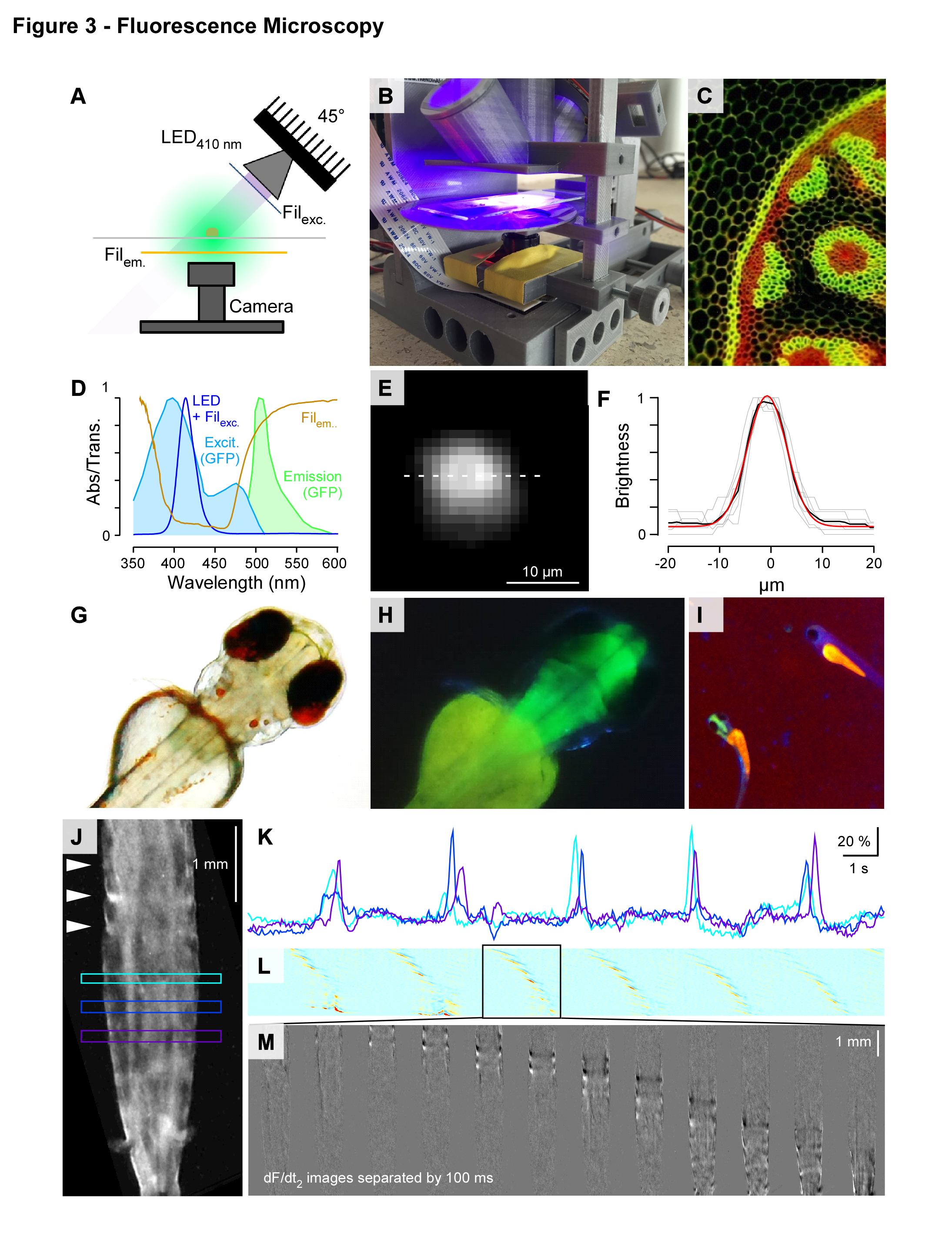
--- using cutting edge tools in neuroscience to both stimulate and record activity from neuronal tissue
![]()
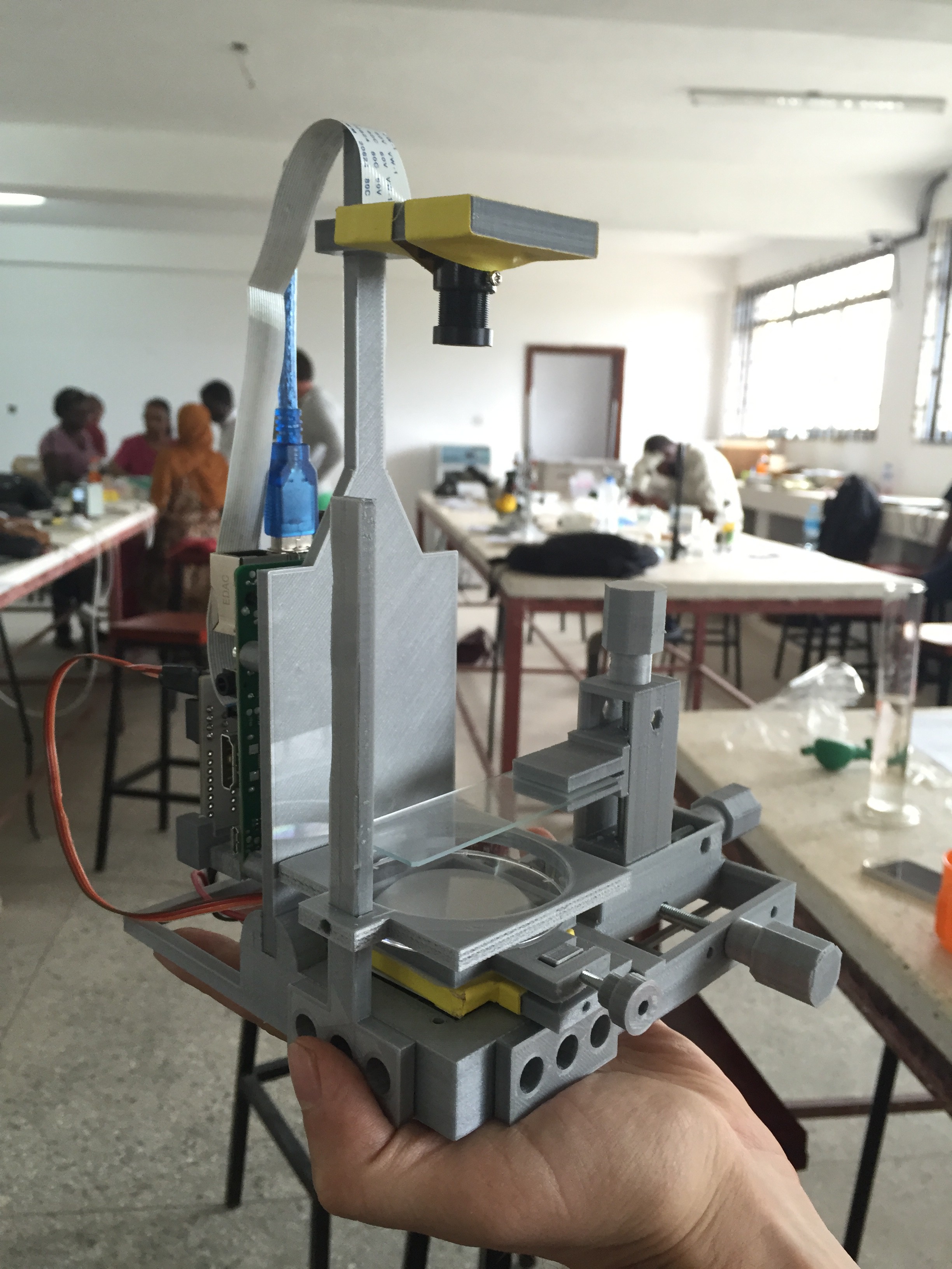
--- portable enough so it can be taken to the remote areas/fit in the DIY biolab garage
![]()
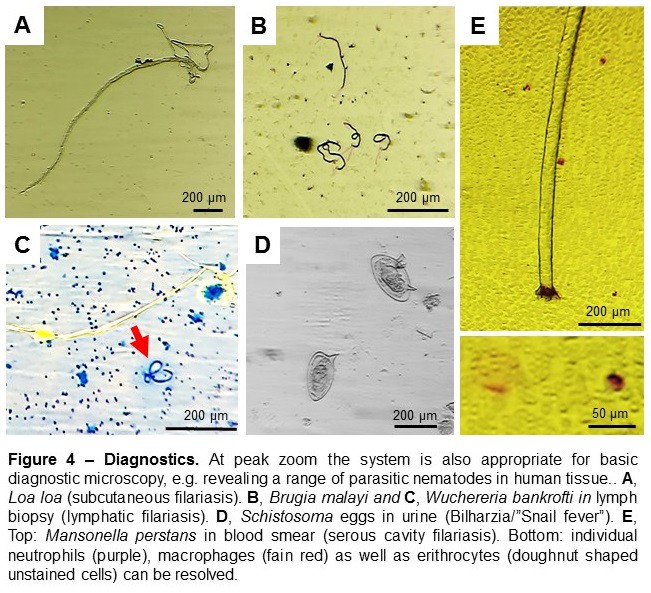
--- Diagnostics - imaging of prepared samples of human tissue that might or not be infected with parasites (so far tested with parasites from the digestive system)
![]()
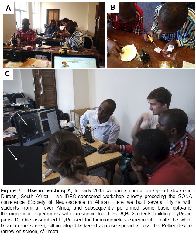
--- Being used as am educational tool. An intro into the basics of microcontrollers, electronic circuits, 3D printing and programming
![]()
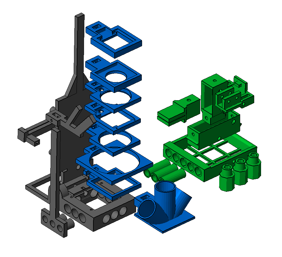
--- Last but not least, it is also modular. If one is only interested in microscopy, them only the Rasperry pi, the PiCamera and the main frame will suffice. If special lighting is necessary, them LEDs of all sorts can be added, If positioning is important, up to three cheap 3-axis micromanipulators (manually or servo adjusted) can be attached to the main frame. And since all programming is done in python classes, adding new features should be fairly straight forward
![]()
-
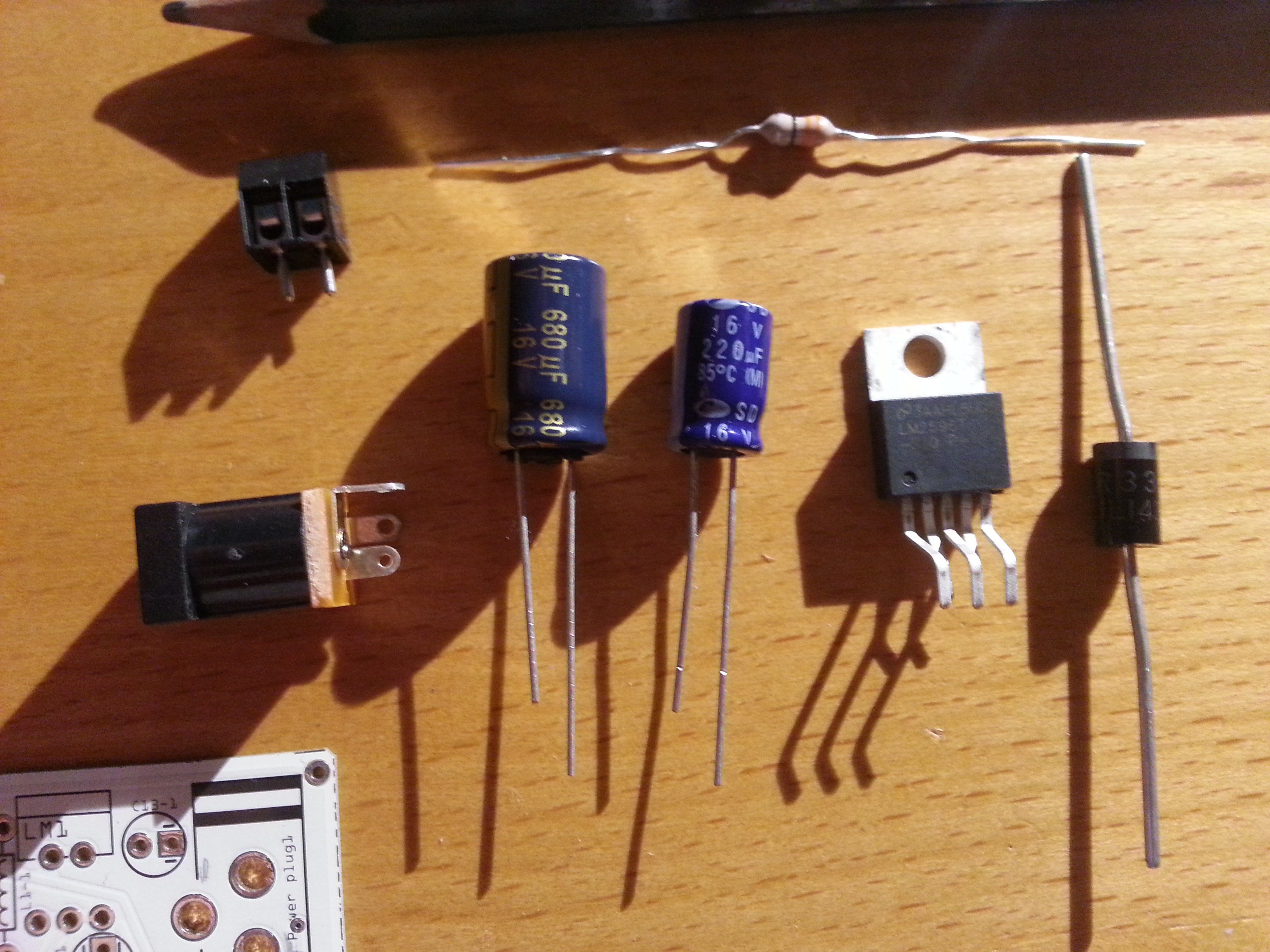
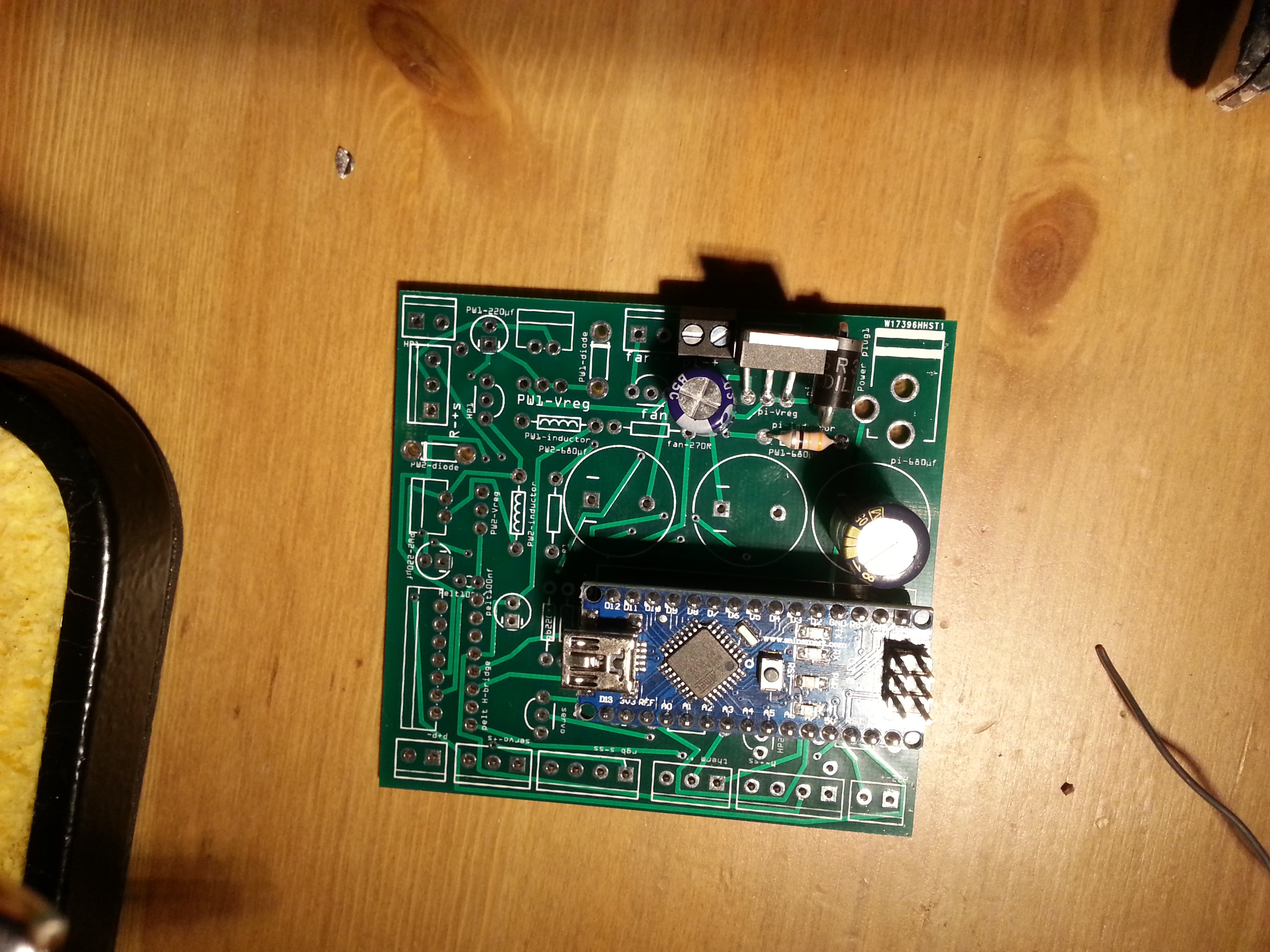
Unified power supply
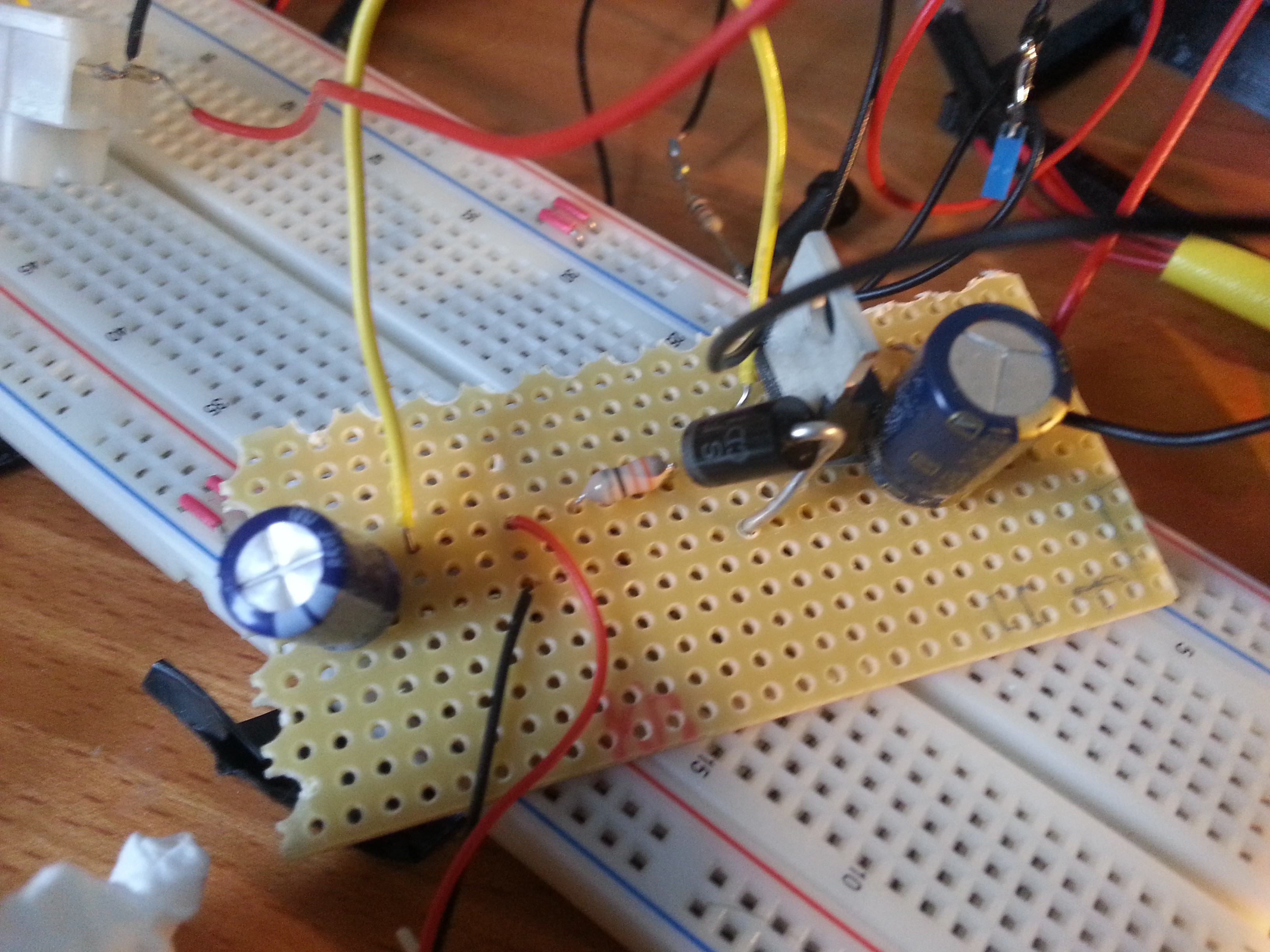
05/29/2016 at 15:40 • 0 commentsSo far the way we were supplying power to our system was only "quick and dirty". The Pi would be powered by a phone charger. All other things would be powered by usb cables cut open and connected to an usb hub. Cables everywhere and very little control over max current and so on...
After playing around and learning about linear/switching voltage regulators, we came up with a system that seems to do the job just right. It consists of a 12V 5A power brick (the ones used for laptops) and switching voltage regulators that power all parts of our system. The power circuit is integrated into the PCB.
![]()
![]()
![]()
-
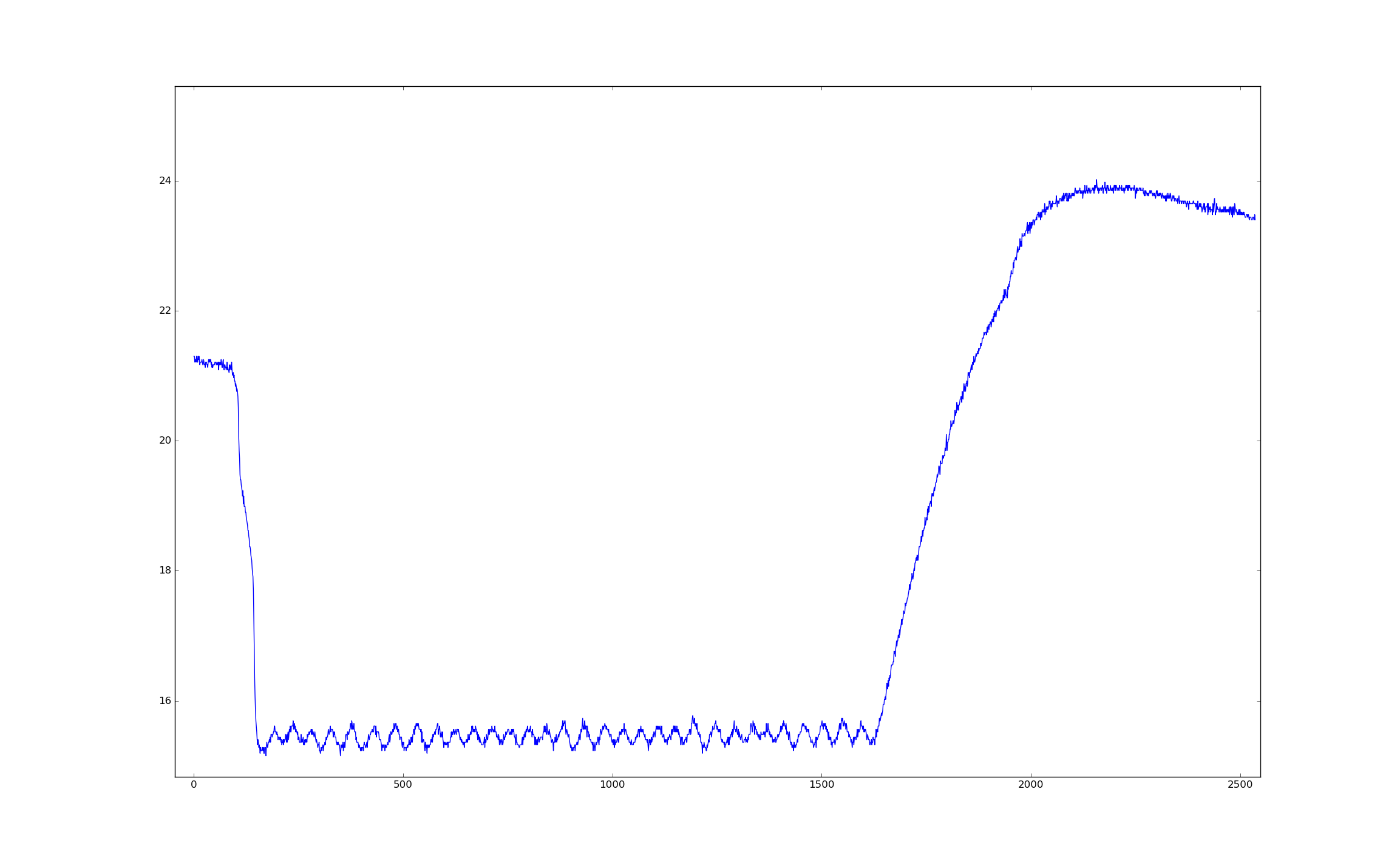
Peltier, it finally works...
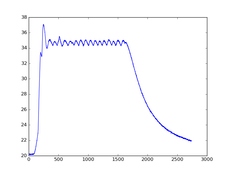
01/12/2016 at 16:23 • 0 commentsFinally the Peltier system is up and running. The solution with the L298N works quite well.. Here some images of temperature curves we logged with it... (it still needs some fine tuning, but it works!)
![]()
![]()
![]()
The images - Room temp to 15 °C. Cycles of 35 to 25 °C and room temp to 35 °C
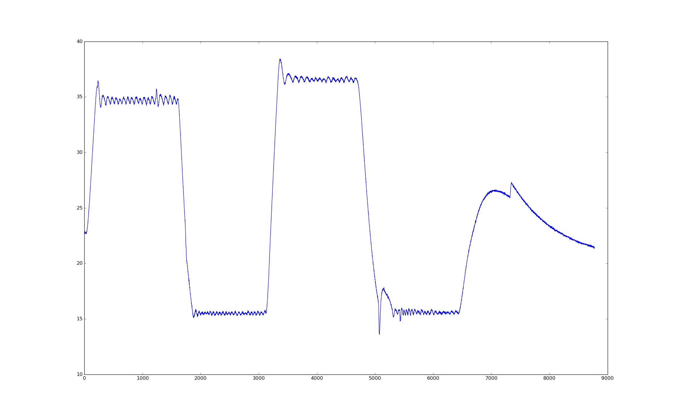
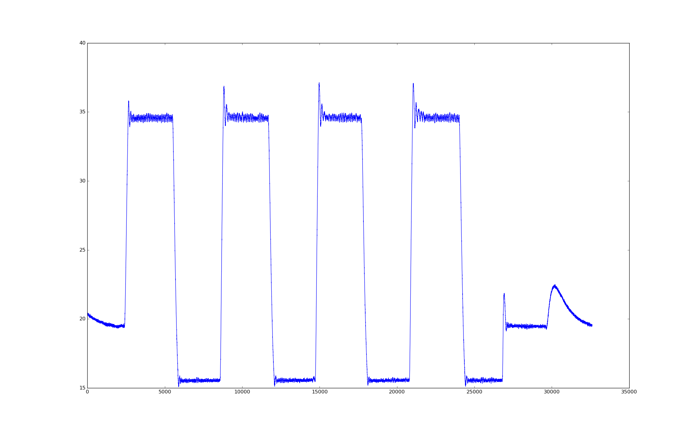
Here after some more tuning:
![]()
5 min periods for each temp. 5min for settling into room temp (after 35°C) than switching between 35°C and 15°C (4X) and one period at 19°C and more 5min with peltier off (the bump comes from heat dissipating from the bottom side of the peltier to the top side, where temperature is measured).
Flypi - cheap microscope/experimental setup
Pi + Picamera + M12 lens + Arduino microscope/experimental setup for diagnostics and scientific experiments!
 Python software schematic: How the different independent classes relate to each other