 akashupase
-
1Step 1: Getting the Parts
OpenBraille uses widely available parts on the market. Most of the components are originally used for 3D printers. The brain of the embosser is an arduino mega with a RAMPS board. The following parts are needed for the build:
Arduino Mega 2560
RAMPS board
Stepper Drivers
End Stops
Servo Motor
Steppers
Rods
Lead Screw Rods
Power supply
Coupler
Bearing
Screws
Printer carriage
10mm wood
-
2Step 2: Printing the Parts
All the parts can be 3D printed. Follow the link and get the files:
-
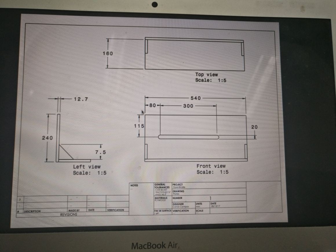
3Step 3: Building the Frame
We used a 10mm Medium Density Fiber Board(MDF) for the frame. It was laser printed according to the dimensions provided in the picture attached.
![]()
-
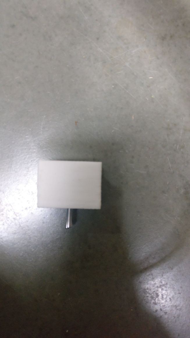
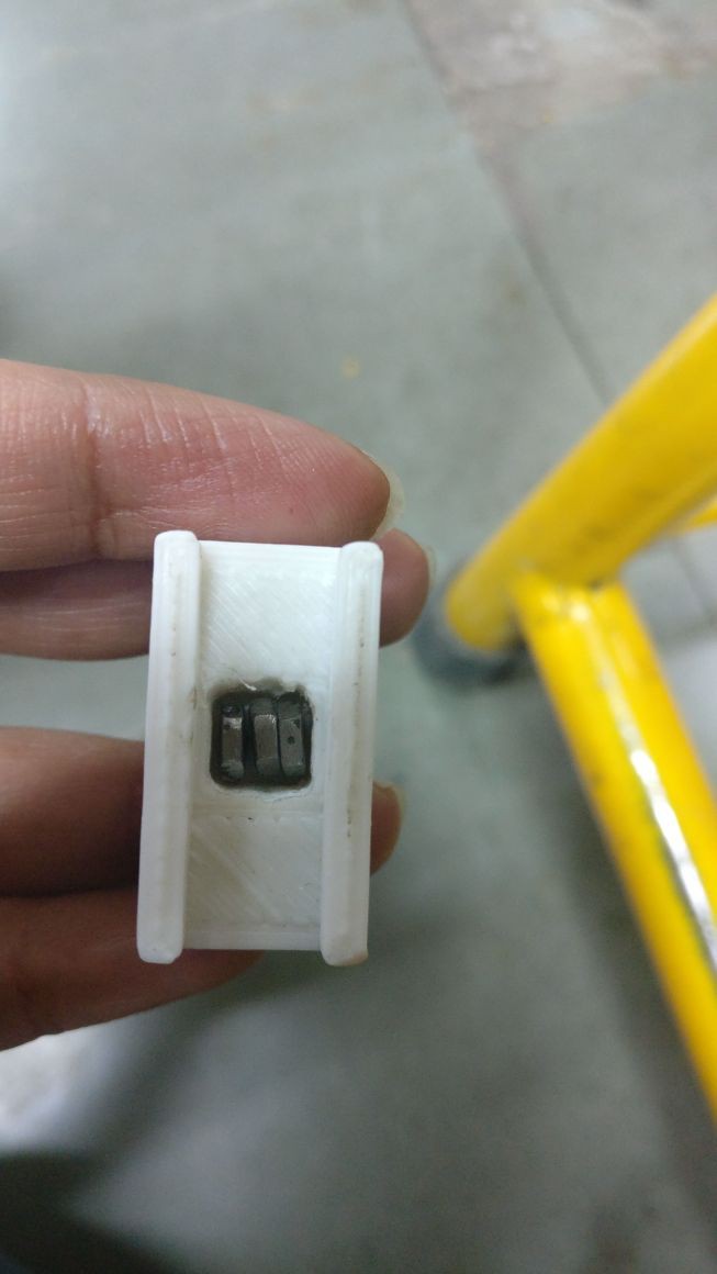
4Step 4: Machining the Pins
The pins are the only components that have to be machined. For each, you will need a nail and a hexagonal nut. As for the tools, you need a rotary machine (dremmel) a vice-grip and a punch.
First of all, the head of the nail has to be cut. The other end of the nail has to be grinded round, this is what will emboss the dots, so, make it pretty.
Then, we have to make a hole on the nut. Use a punch to guide the hole. Then, use the dremmel to finish the hole.
Finally, with a soldering station, add a drop of thin on the nut so to fix the pin on it.
![]()
![]()
-
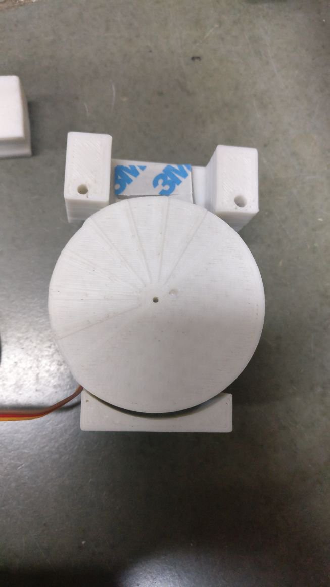
5Step 5: Assembling the Encoder
![]()
![]()
![]()
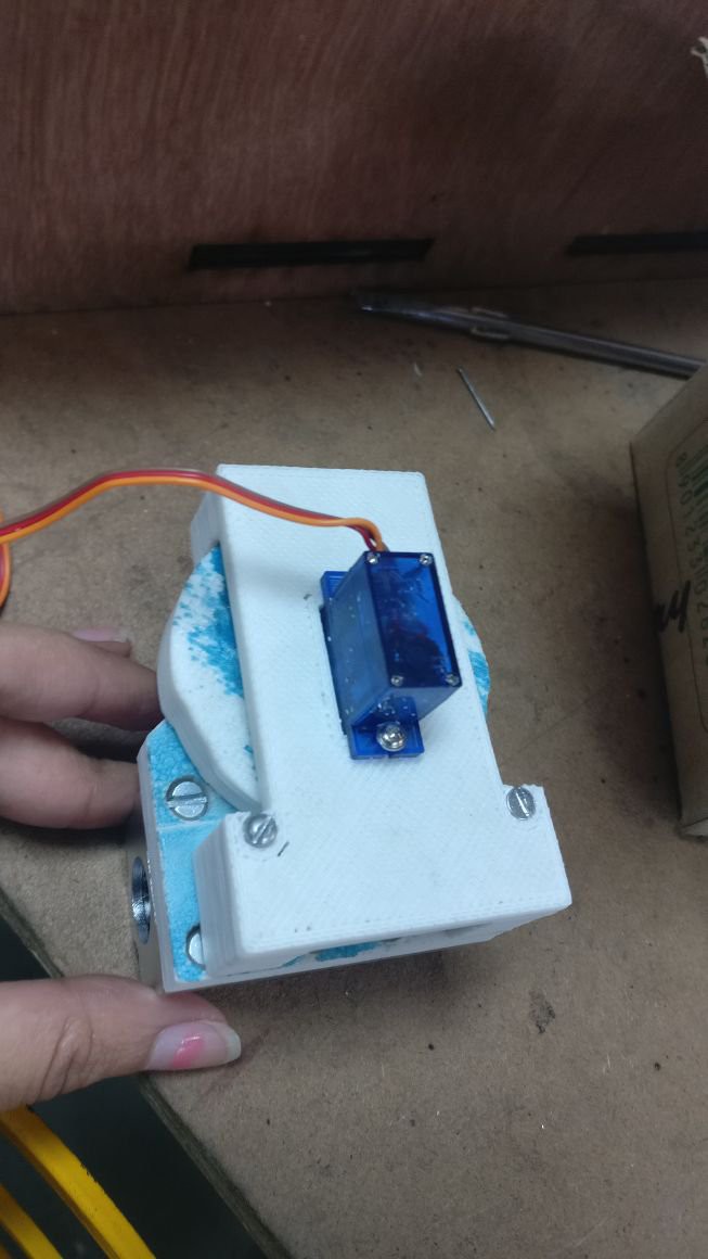
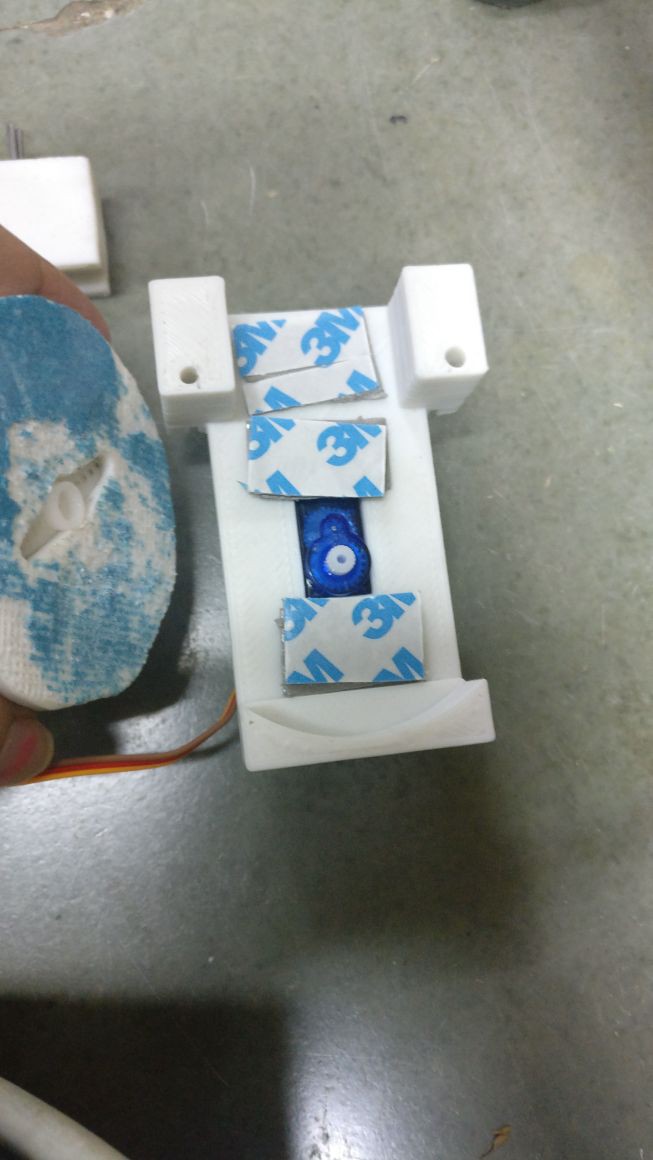
The 3d printed parts have to be cleaned for them to fit nicely. The holes for the pins are smaller. Therefore, by using a dremmel with a bit of the size of the pins the holes will be perfect.
The servo is attached to the wheel by press fitting it inside. Then, the wheel_base has to be sandwiched together with the servo and the wheel.
The pin holder goes on top of the wheel with the pins pointing toward the top.
Before finishing this part, the bearings have to be mounted to the bearing_support_inverse (as named on the files). The bearings are made for M4 screws.
Finally, the wheel base is mounted on the bearing support with two M3 screws. I had to drill a little extra hole on the corner of the wheel base for stability, and I used a third M3 screw.
-
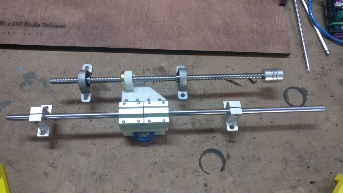
6Step 7: Screwing the Rods
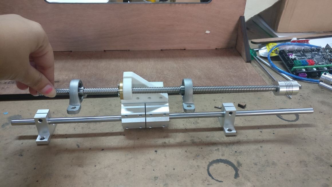
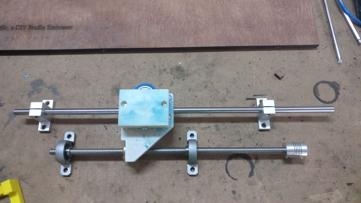
There are 4 rods. Two linear rods for the bearings and two lead screws rods. All the rods have to be in the same plane. For that, there are four spacers that go underneath the lead screws brackets.
All the rods have to be parallel. For the linear rods to be parallel use the Calibration_spacer and the Endstop_holder. For the lead screws to be parallel to the linear rods use the roller assembly and the encoder assemble. Places the assemblies on the far right and screw the brackets into the board. Place the assemblies on the far left and screw the rest of the brackets. The lead screw should be free to turn.
![]()
![]()
![]()
-
7Step 8: Adding the Steppers
The steppers are mounted to the board with the NEMA_support. The support has two holes for M3 screws. Screw the support into the stepper and insert the coupler into the shaft. I got the wrong kind of coupler so I had to put shrink tube for them to fit nicely. Now, connect the steppers to the lead screw with the couplers. Make sure its straight and screw the support into the board.
-
8Assembling the electronic components
1. Assemble the arduino board and RAMPS boards by placing arduino on top of it (ensure that the placement is proper). Now put the drivers for the axes respectively and connect with the SMPS for power supply. Connect the stepper motor with the arduino. (Note: In all the connections, ensure that the pins are inserted properly whether it is negative, positive or for signal. Check color coding of wires for the same.)
2. After installation of Arduino, open the Arduino IDE and load the file Marlin.ino present in the folder Marlin within the open-braille downloaded files (from github). Here we have used Arduino Mega 2560, so select this board from Tools->Board.
(.ino files basically loads all the files in arduino)
3. Go to configuration.h file and see the Mother Board name (#define MOTHERBOARD) to ensure that the proper motherboard is selected (Here we use #define MOTHERBOARD BOARD_RAMPS_14_EEB). In case your 3D-printer has different motors, the axes settings need to be changed correspondingly, for this, one needs to understand how to make hardware setting for Marlin firmware.
4. With the board connected to laptop via arduino USB cable, compile and upload the files onto your arduino board by clicking on the right-pointing arrow below the Edit option. -
9Software installation and printing
1. After installing the right kivy for your platform, run 'python setup.py install' on command prompt/terminal.
2. Now run the brailleGUI.py file (python brailleGUI.py) to open the interface for printer.
3. Click on the send icon (arrow in green) to select the COM port for arduino.
4. Insert the paper. Type the content to be printed (letters, digits, punctuation signs) and click on the printer icon.
5. You now have your braille embossing. :)
OpenBraille Steam
Using a low cost braille printer using the open source project
Discussions
Become a Hackaday.io Member
Create an account to leave a comment. Already have an account? Log In.