-
Time for a breather
10/05/2020 at 14:09 • 0 commentsJust a little log to share my thoughts, only a few minutes after the deadline.
I had not intended to finish everything in a mad rush, and I hate to use this excuse, but CORONA happened! Or rather, the UK government was threatening to put us all in a lockdown again, at which point I decided to visit my mom abroad a month earlier, taking away a great deal of tinkering time.
Looking back, I'm quite pleased with the write up and the program itself, considering the short amount of time I had to construct everything. Since I've uploaded the source files, I'm pretty confident someone with a bit of patience can work out how to use my work and create something theirselves.
It was a bit of a shame I did not have more time to pretty up the prototype itself, but it did do what it was meant to do, and display the concept. People will just have to look past that I had to operate the limit switches by hand because I couldn't add them to the rig on time.
I've at least described how it should have worked.
If I understand correctly, I will hear in a month time if I have won anything. In the meantime, I may make some more videos about my project, even though these strictly speaking will not count for the prize.Especially the hack I came up with to use the USB-TO-UART device to control a stepper motor driver. I don't think anybody else has come up with this yet, and it brings stepper motor tinkering more into the hobby domain, because you won't have to buy 3rd party drivers or use an Arduino type device, which is not terribly difficult but does add a layer of complexity.
-
Mechanical bits!
10/05/2020 at 12:54 • 0 commentswell, I ran out of time but I managed to hack something together.
The video is uploading now..
![]()
![]()
![]()
![]()
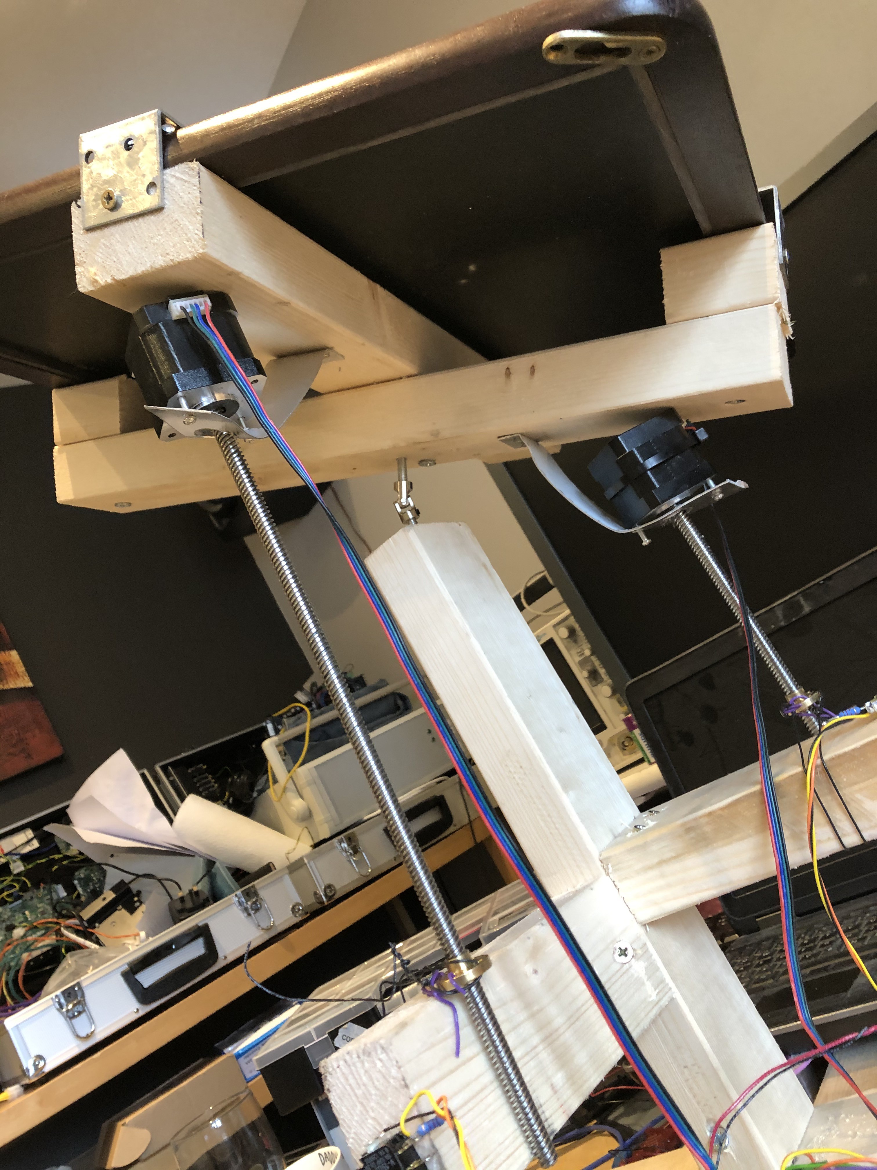
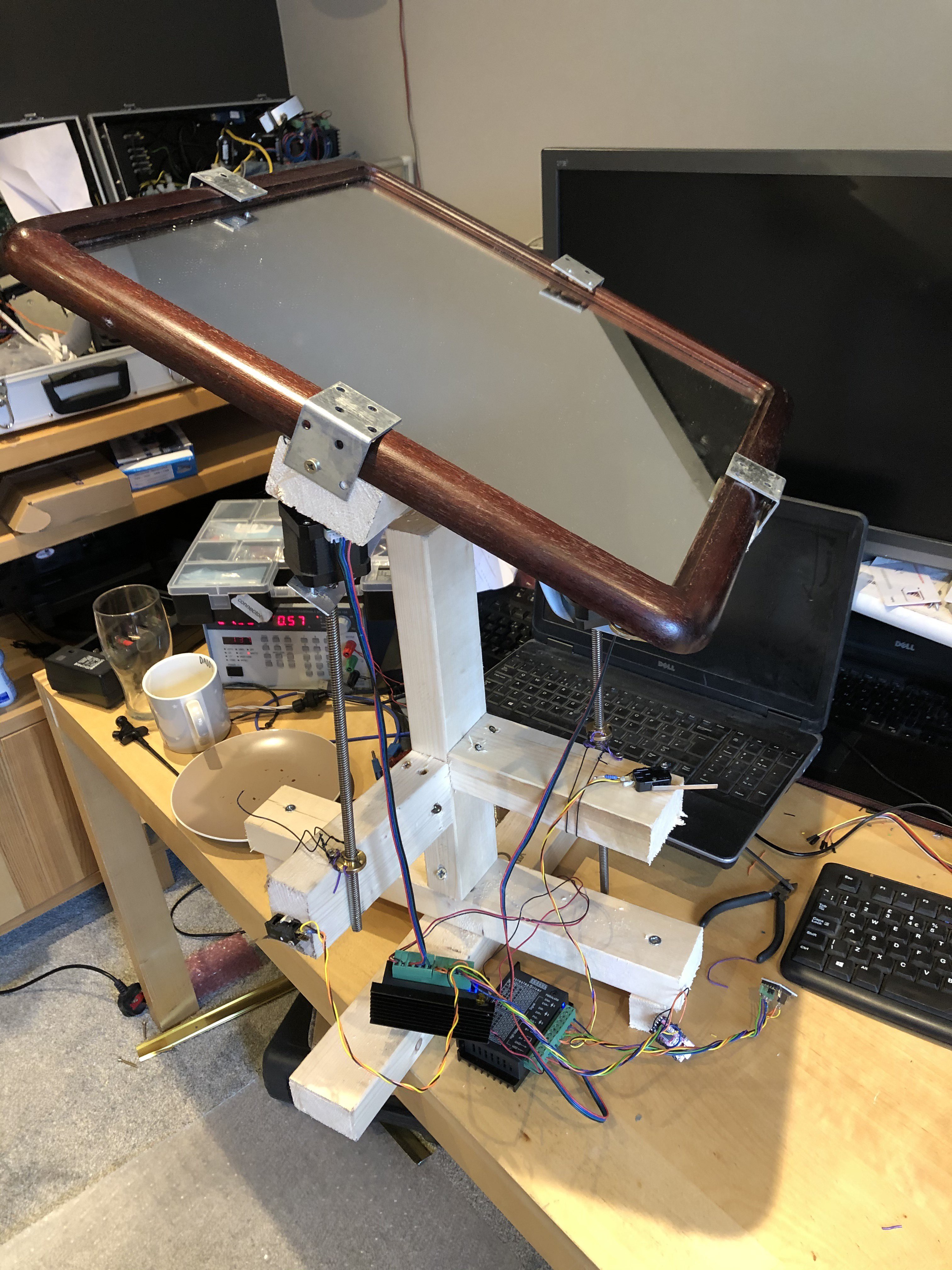
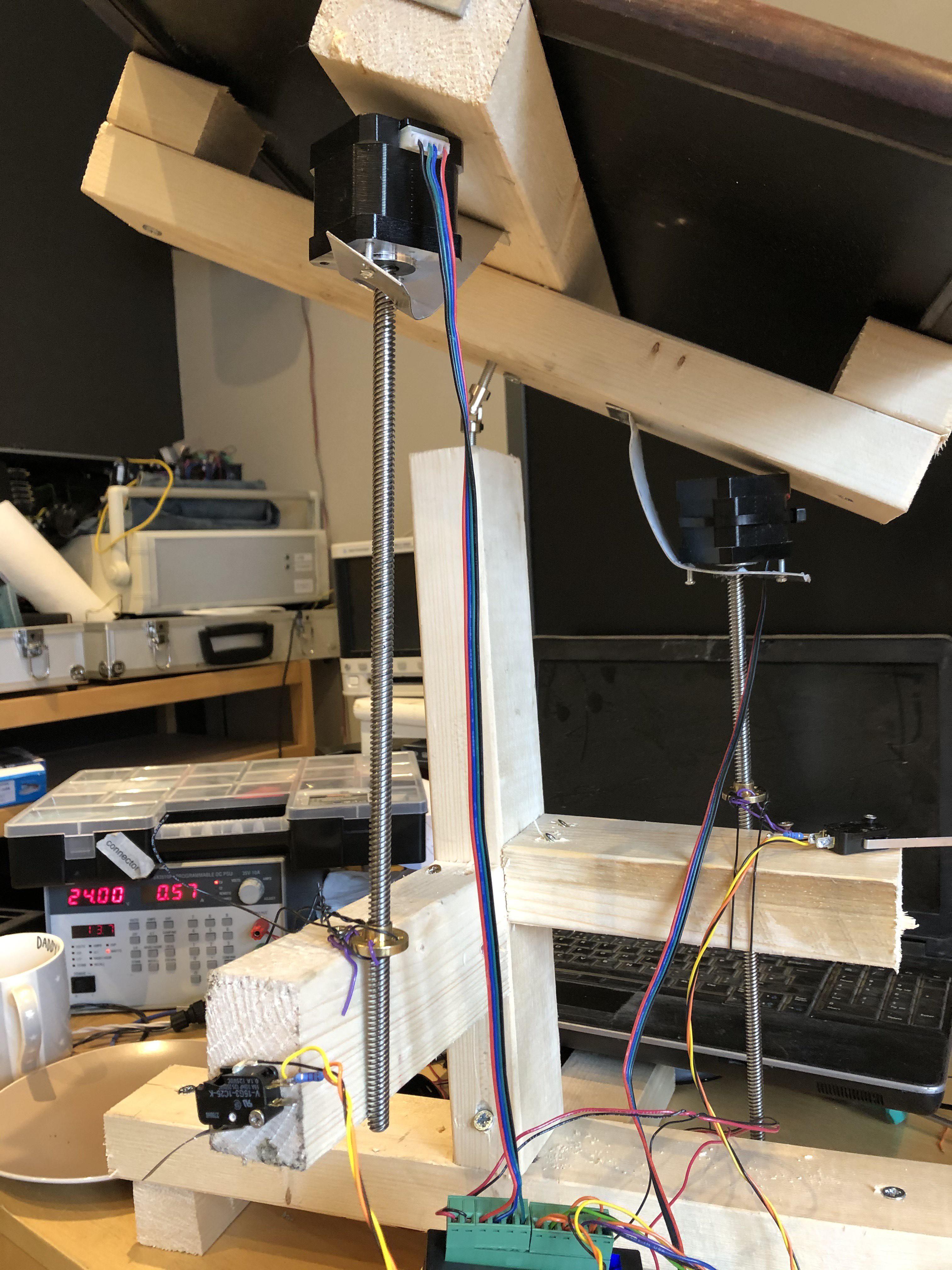
So I created a simple frame, and I added the motors to the frame.. Not in the way I intended!!!!! ;)
In order to finish it, I quickly tacked on the limit switches. You can go a few logs back to see how it is meant to look.
But roughly speaking, this is how I wanted to construct the frame.
List of components:
wood
screws
aluminium strips
mirror
The other components are already listed on the electronics bit.
-
Labviewing: the main program in steps
10/05/2020 at 08:55 • 0 commentsZeroing the axes.
When the system is started up, the actuator could be in any position. That is why it first needs to be zeroed out.
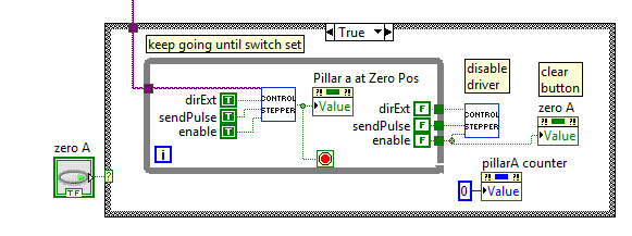
The main program has this little snippet:
When the zero A button is pressed (on the left), the "control stepper" subroutine is given the command to keep going until the pillar is at zero position. Then the pillarA counter is set to zero.
At the start of the program, the pillarA counter is set to -1 and the zeroA button is set programmatically, so that immediately, the system goes to the zero position. When the position is at -1, the system knows not to try to adjust anything automatically based on the angle program (from the program.csv file), but wait for a rezero-ing to happen first, otherwise things may break.
At any point in time, the user can zero the system by pressing the zero A button. But the user should not have to get involved.
The same code is of course used for pillarB, so I won't repeat that.
Determining which program point should be active
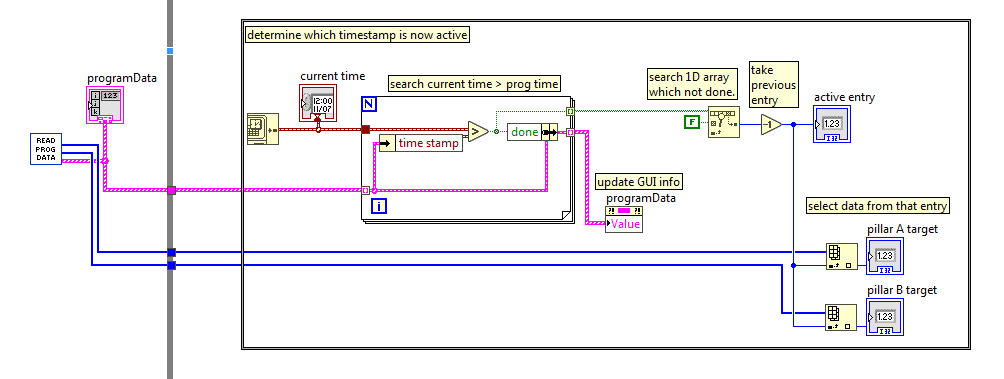
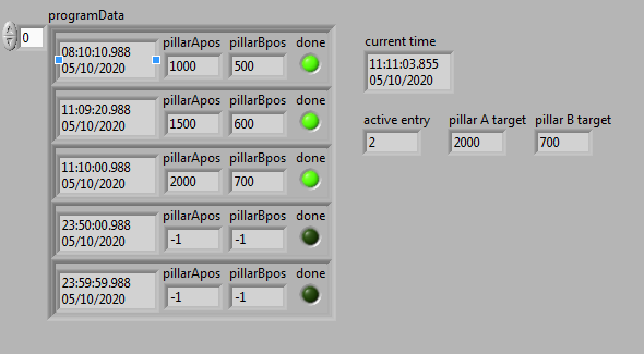
In order to determine which program point is now active, the program data is read, and the current time is sampled.
Then it is determined which time stamps have NOT been done yet, and the first of those timestamps is selected by going back one step. The GUI is updated, and the new pillar data is updated.
The picture above should give you a better idea. The current time is shown, and the program has determined that all the datapoints with a time earlier than the current time have been done. The active entry is 2, and its target positions are 2000 and 700 for pillar A and B respectively.
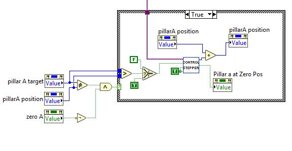
Driving the motors to get on target
The pillar A and pillar B targets which were generated in the previously discussed block are used to drive the motors to the correct positions:
If the "zeroA" function is not active of course. We don't want zeroing and driving the motor to the programmed position to be active at the same time!
This bit of code should be easy to understand: if the target value is unequal to the position, the loop is activated. If the target value is larger than the position value, then the stepper motor is extended, and otherwise retracted. The pillarA position is of course updated.
Needless to say, the same code is repeated for the pillar B, and I won't repeat that again.
So I've discussed all the program features!
1) upon startup, zero the pillar A and pillar B by extending until the limit switches are activated. This will reset the position counter.
2) upon startup, the program is also loaded, from a CSV file.
When the program runs:
3) from the program data, the active program entry is determined and the targets updated
4) the targets are compared hundreds of time per second with the actual position and the position is automatically updated.
It does require the user to set the appropriate targets. This can be done by controlling the actuator positions within the program, and writing down in the CSV file what the position should be at what time of the day.
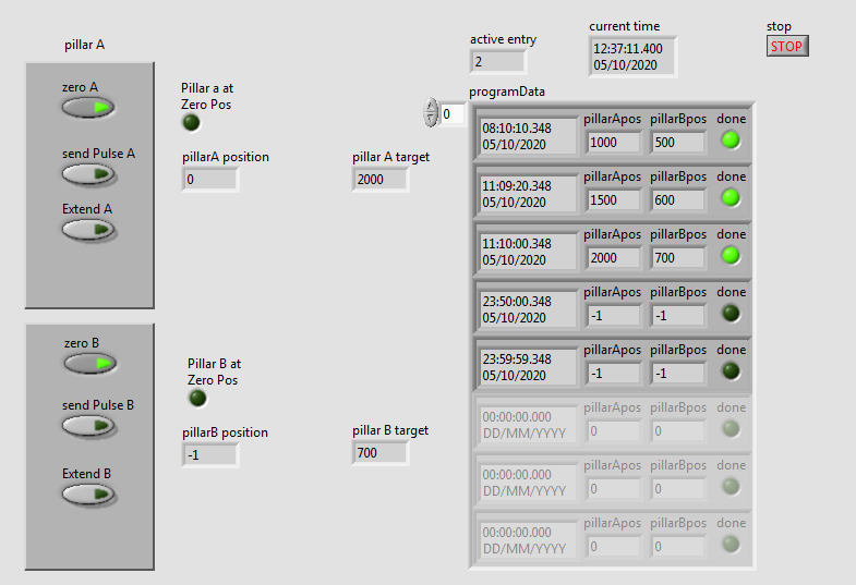
This is what the program GUI looks like just after startup. Both zeroA and zeroB are active, although zeroB waits for zeroA to finish before zeroing - to ensure minimal interference.
After zeroing, the pillar A at Zero Pos will momentarily be lit, but immediately, the program is analysed, the active entry determined, and the pillar A and pillar B targets determined. Here also, pillar B waits for pillar A to finish moving.
-
Labviewing: reading mirror angle program
10/05/2020 at 08:00 • 0 commentsWe can now control the motor and read whether it has reached the zero position. But we don't want to move the mirror ourselves all day. Ideally, there should be a program which can be loaded, to which the mirror angles will be adjusted.
I've chosen that this program can be set by the user using a file in the Comma Separated Value (CSV) format. This is a super easy spreadsheet format and is recognised by all spreadsheet programs.
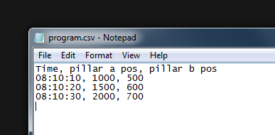
The spreadsheet saved as a regular text file, so you can see its contents in Notepad, and is formatted as follows:
The first column is the time stamp, the second column the required pillar a position, and the third column the required pillar b position. All data is separated by a comma, that is why it's called CSV.
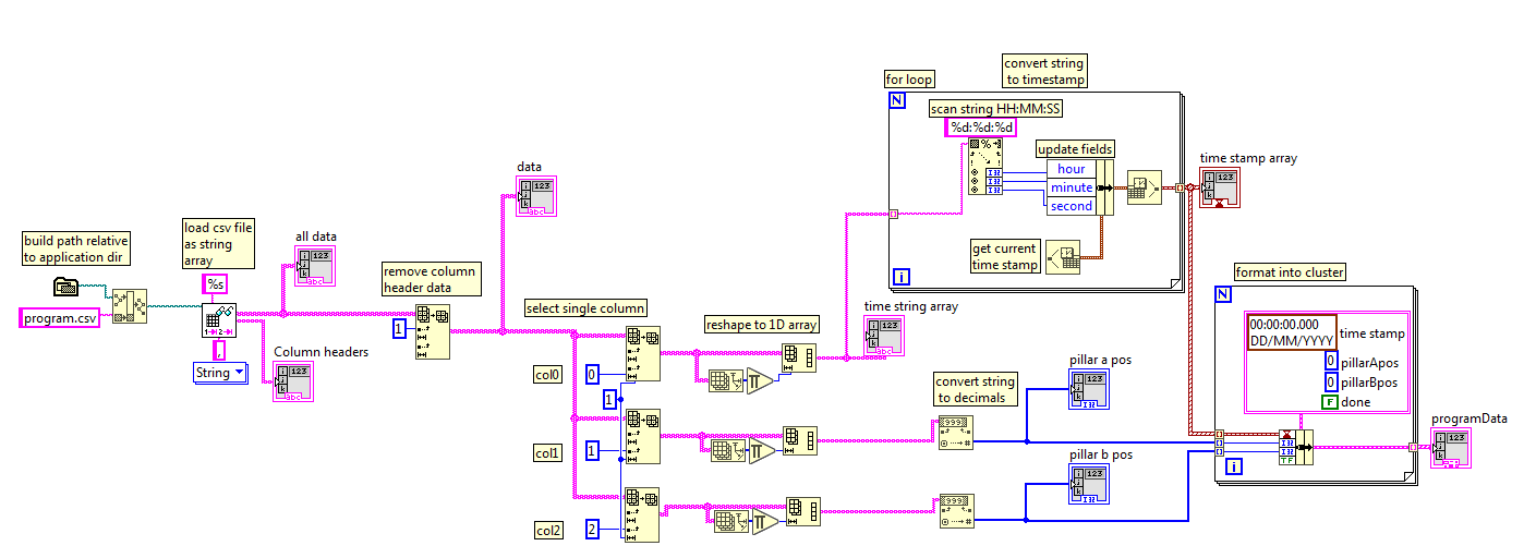
To load this into Labview, I've created another subroutine "read program".
There are some things going on which take it beyond the "beginner" stage, but it's not too hard to understand.
On the far left, the path to the program.csv file is built by using the application path and tacking on "program.csv". The file is then loaded by "read delimited spreadsheet". The header data is removed from all the data by selecting everything from row 1 onwards (row 0 is the header data). From there on, columns 0, 1, and 2 are selected separately to process the time, pillar a position, and pillar b positions.
Labview then still thinks a 1 column array should be presented as a 2D array, so it's reshaped into a 1D array.
The time string array cannot be used directly to compare time, it first needs to be formatted into a time stamp. This is a bit more tricky, and involves parsing the time string (in 24H format), to get hours, minutes, and seconds, and updating those fields in a time stamp, so that the current date (day/month/year) is also correct. It may not make a lot of sense, you'll just have to play around with it to see.
Then the time stamps are in the correct time stamp format.
The pillar a and b positions need to be converted from strings to decimals.
This subroutine then exports three arrays: the time stamp array, the pillar a position array, and the pillar b position array.
Finally, the data is formatted in a cluster. This is a data format similar to a structure or object; instead of having 3 arrays with timestamp, pillarApos and pillarBpos, there is one array/list/structure/cluster in which each entry has one time stamp and the corresponding pillarApos and pillarBpos. Sometimes this makes it easier to process data and not accidentally select the wrong position for the correct time. The cluster also has a datapoint "done", which is not loaded from the program.csv but used in the main program to keep track of which data points have already been processed.
The cluster information will then be used in the main loop to check if the mirror angles are in the correct position: in a continuous loop it checks the actual time, in which position the mirror should be in, based on the program.csv, and in what position the mirror is now.
More about that later.
-
Labviewing: motor control
10/05/2020 at 05:55 • 0 commentsOn a previous post I already discussed why I chose Labview to create a prototype. I like how it very quickly and easily allows you to create a prototype.
I've installed the free (for non-commercial and non-academic) community version 2020.
https://www.ni.com/en-gb/support/downloads/software-products/download.labview.html
Let's dive right in.
Remember that I'm using the FT232RL usb to uart converter? I'm using the TX to send a pulse, and the DTR output to set the direction.
This little sketch allows you to play around with it.
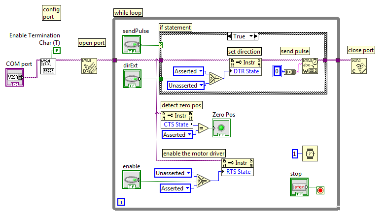
First the COM port is opened. You'll have to figure out for yourself which one that is. What I typically do is open the device manager in windows, look at the list of COM ports, and disconnect and connect the FT232RL device. The device which disappears from the list and reappears is the one you want.
The COM port is then configured with all the standard settings (9600 baud, 8n1), but the termination byte is disabled. This is a newline character, and we don't want this: we only want the bytes we want to send to appear on the output and no extras.
Then there's a while loop and within the while loop it polls the sendPulse button. If that button is pressed on the GUI, a serial character 0x00 is sent, which appears as a single pulse with a length of approximately 10/9600 = 1 ms length. Within the while loop there is another button, and if that is enabled, its value will be carried into the if statement when it is executed, and the motor will turn in such a way that the actuator extends, and if disabled, the actuator withdraws.
The direction is wired in such a way that it executes before the "send pulse" is executed. This is important for counting the pulses in the correct direction in order to figure out where the actuator is.
There is a button "Enable" which, when enabled, enables the motor driver. When disabled, the motor driver is put in standby and doesn't energise the motor. If you're playing around with this code, you'll notice that the motor refuses to move when the motor driver is enabled.
Finally, the CTS state is checked, and this line is connected to the switch. So when the switch is pressed, the CTS state is asserted, and through a comparison "equals" block, turned into a boolean LED signal.
This is all which is required to control the motor and detect the zero position!
Didn't I say it was a super simple way to control a stepper motor actuator?
There are a few details: there is a time delay of 1 ms in the while loop so that the pulse repetition is slowed down to maximum 1000 per second, and if the program is stopped, the serial port is closed again.
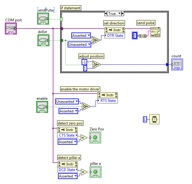
In order to use this bit of code as a subroutine, there are some small changes:
The picture above shows the contents of the subroutine. The while loop is removed, as well as the "open port", "configure port", and "close port". Those things will be handled in the main routine. Executing those things every time you run this code slows it down enormously. The inputs to this subroutine are "COM port", "sendPulse", "dirExt", and "enable". The output is "Zero Pos". I've shown what this looks like below. Notice I've added a detection whether this COM port is pillar a or pillar b. Remember from an earlier project log that pillar a is connected to ground, and pillar b is connected to 5V, so that from Labview I can determine which COM port corresponds to which pillar.
There is also a bit of code that helps counting the position of the actuator: if the direction is "extending", then the count is -1 and else it is +1.
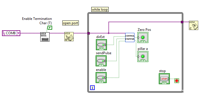
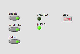
This is what the main loop looks like up to now: the "control stepper" block contains the subroutine described above. On the left of the "control stepper" there are four inputs (3 buttons and the link to the COM port), and on the right of this block are the two outputs; "zero pos" and "pillar a".
I haven't yet figured out how to add the source code of this Labview program to this project log, but the screenshot is the source code, really.
This is what the Graphical User Interface looks like:
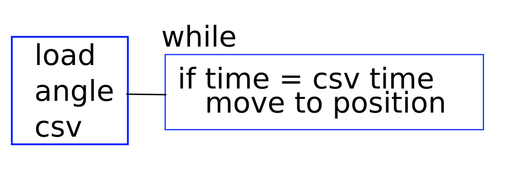
This of course is not all of the program. Let me try to describe my plans first.
The above program describes how it will work, really. When the program is started, a CSV (comma separated value) spreadsheet is loaded. Within the CSV file, the first column contains time stamps in ascending order. The second column contains the angle of pillar a (see an earlier project log which describes how it's all built), and the third column contains the angle of piller b. These pillars control axes which are perpendicular (at 90 degrees angle) of each other.
When the CSV file is loaded (into a Labview structure or array), the main while loop starts. This loop keeps running until the user shuts the program down. Within the while loop, the time is continuously compared with the CSV data, and when the time is larger than one of the CSV rows, the program checks whether it is already in position, and if not, it moves to this position.
Not shown are some details, such as: figuring out what the current position is by keeping track of which pulses were sent, detecting the DCD status to automatically figure out which COM port is which axis, and things like that.
Once a day, there should probably be a possibility to "zero" the system, so that the required position is actually the position it has achieved.
-
The schematic
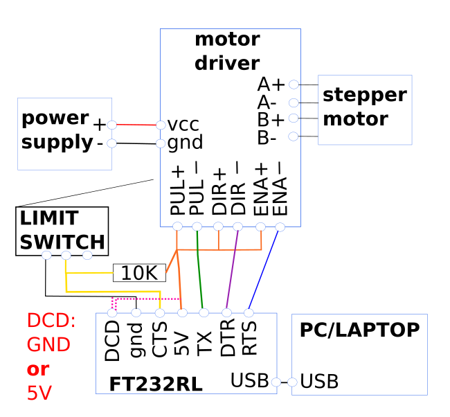
10/04/2020 at 20:02 • 0 commentsThis is a super simple schematic, even though it may look chaotic at first glance.
Notice that I have not connected the power supply ground to the FT232RL ground. Only when it absolutely does not work without, should you do this, really. Connecting them may actually cause problems, especially if it's a switching power supply that is a bit 'nasty'. All the motor driver control inputs are optically shielded anyway, which is good.
First of all, we require a power supply. The motor driver I used, the TB6600 (https://www.makerguides.com/wp-content/uploads/2019/10/TB6600-Manual.pdf) requires a DC voltage between 9-42 VDC. The prusa motors that I got from Ebay did not specify what current they wanted, but comparable ones from Amazon require 1.5 A. https://www.amazon.co.uk/gp/product/B01DVD87Q6
Remember to configure the motor driver current to 1.5A. This is described in the manual, link above. Configure the microstep to "1", which means "let's not bother with microstepping for this".
So let's use 1.5 per stepper motor. Typically, the higher the supply voltage for the power supply, the happier the steppers are. Because we have two stepper motors in our 'mirror system', we need 3A in total.
It's super easy to find 24V switching power supplies, for instance:
https://www.amazon.co.uk/Vbestlife-100-240V-Converter-Switching-Transformers-default/dp/B07KPCCQBS, which is a 24V, 4A power supply. It's always better to have a power supply which can supply more current than required, and these types of switching power supplies come with built-in current limit detection. If anything goes wrong, it won't (should not!) self destruct. And touching 24V is not going to kill you.
For the motor driver I'm using the TB6600, as already mentioned. On its right, it has 4 outputs: A+/- and B+/-. A and B are the two windings of the prusa style actuators; I got these from Amazon:
https://www.amazon.co.uk/gp/product/B01DVD87Q6
If you don't know which of its 4 wires belong to output A or B, just use a multimeter in the continuity or 'beep' setting, and find the two wires that 'beep' when you test them. Call them winding A or B, it doesn't matter, unless you're building multiple mirrors, in that cause you'd like to have the correct pair, otherwise the different mirror systems will react differently to the control signals (direction of turning may change). Also test that the remaining two wires 'beep', and connect them to the motor driver. The motor driver has to be close to the motor, because it doesn't really like to drive long leads. It may work if the pulses are quite long, such as 1200 baud or so, but I digress.
So connect the wires that you call A to the output A and the wires B to the output B. Again, it doesn't matter which way around they go, it only matters if you build multiple systems and you want all mirrors to behave the same.
Because in the Labview program, you can easily change the DIR signal (direction).
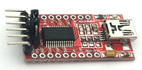
Okay, so we come to the FT232RL converter. There are several signals:
TX: to send the pulses
5V (orange) : this output supplies 5V to the TB6600.
TX to PUL (green): this provides the pulses, as discussed in an earlier project log.
DTR to DIR- (purple): this provides the direction signal.
CTS to ENA- (blue): this provides the "enable" signal. If this signal is low, then the motor driver is enabled. This signal needs to be high when the mirror is not adjusted at that time, otherwise the motor driver will continuously use power. This is not going to destroy anything, but wastes energy, and that is more or less what this project is trying to prevent, right?
DCD (pink dotted): connect to 5V or gnd NOT BOTH!! Why this signal? Remember, we're going to have two motors in this system, and it would be nice to be able to identify them easily, and not get the axes switched accidentally, sending the mirror in the wrong direction. So for one of the axes, this signal has to be high, and for the other axis, low. This signal can then be read in Labview.
RTS (yellow): When this signal is high, the limit switch is not engaged, and when this signal is low, it is engaged. The signal should always be high because it is pulled up by a 10K resistor, and the switch merely shorts it to ground. The 10K resistor then limits the current to a safe level (5V/10K = 0.5 mA).
Note: due to historical reasons, a "high" signal, or "engaged", or as Labview calls it "asserted" may be high or low. In other words: experimentally it needs to be verified whether asserted is 5V or 0V, and unasserted the other way around.
That is the entire schematic! Well, half of it of course, because the same system needs to be duplicated for the other axis.
summary of list of electronic components:
- power supply: https://www.amazon.co.uk/Vbestlife-100-240V-Converter-Switching-Transformers-default/dp/B07KPCCQBS
- plug for power supply connector: https://www.amazon.co.uk/EFISH-Connector-Terminal-Adaptors-Security/dp/B07RHM5KCW
- a long thick wire pair to connect the power supply to your mirror system outside: https://www.amazon.co.uk/MANAX-speaker-cable-mm%C2%B2-black-Red/dp/B01DDJX920
- 8 core shielded cable for the signals, such as cat7 cable: https://www.amazon.co.uk/100-0M-Cat-7A-Ethernet-Network-Halogen/dp/B0749NQRK3 . The shield has to be connected to ground on the power supply side.
- some 8 pin connectors: https://www.amazon.co.uk/Thread-Female-Aviation-Connector-Ltsstoreuk-Silver/dp/B07BFDFJ1T
- actuator: https://www.amazon.co.uk/gp/product/B01DVD87Q6
- motor driver: https://www.amazon.co.uk/TB6600-Stepper-Driver-Controller-Segments/dp/B07FXH9TYM
- FT232RL: https://www.amazon.co.uk/Yizhet-FT232RL-Converter-Adapter-Raspberry/dp/B07R17BMTL
- 10K resistor: https://www.amazon.co.uk/POPESQ%C2%AE-Resistor-Suitable-0-25W-A2428/dp/B07KX4YVY3
You probably need some wires https://www.amazon.co.uk/TUOFENG-Wire-Solid-Different-Colored-spools/dp/B07V5FVSYLand a soldering iron and some tools: https://www.amazon.co.uk/Soldering-Multimeter-NO-Soldering-Welding-Cutter/dp/B07F2XNTWV
- and a windows PC or Laptop.
I've just given you some quick examples. If you do a bit of sleuthing, you will probably find cheaper components, which may do the job just fine.
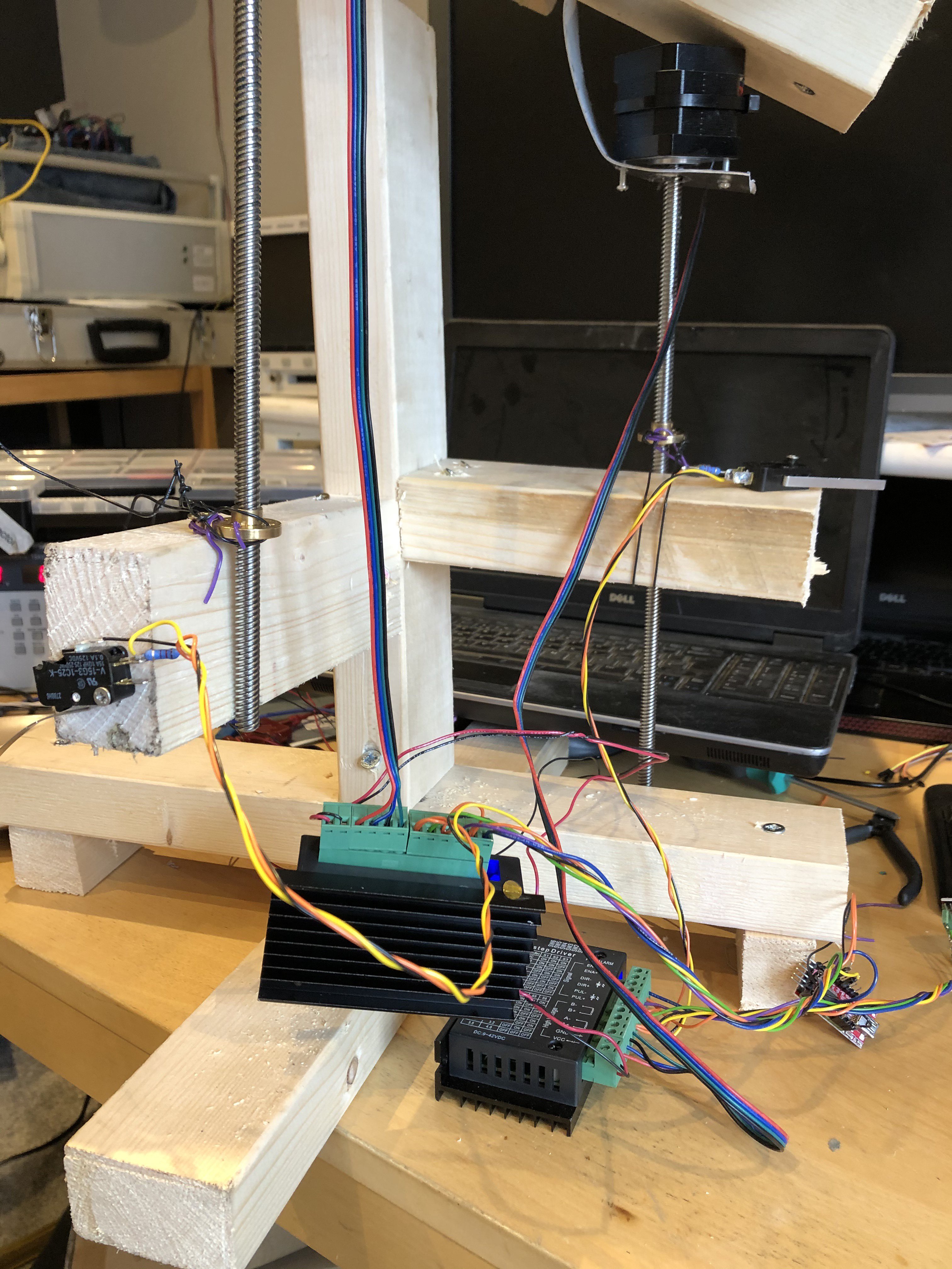
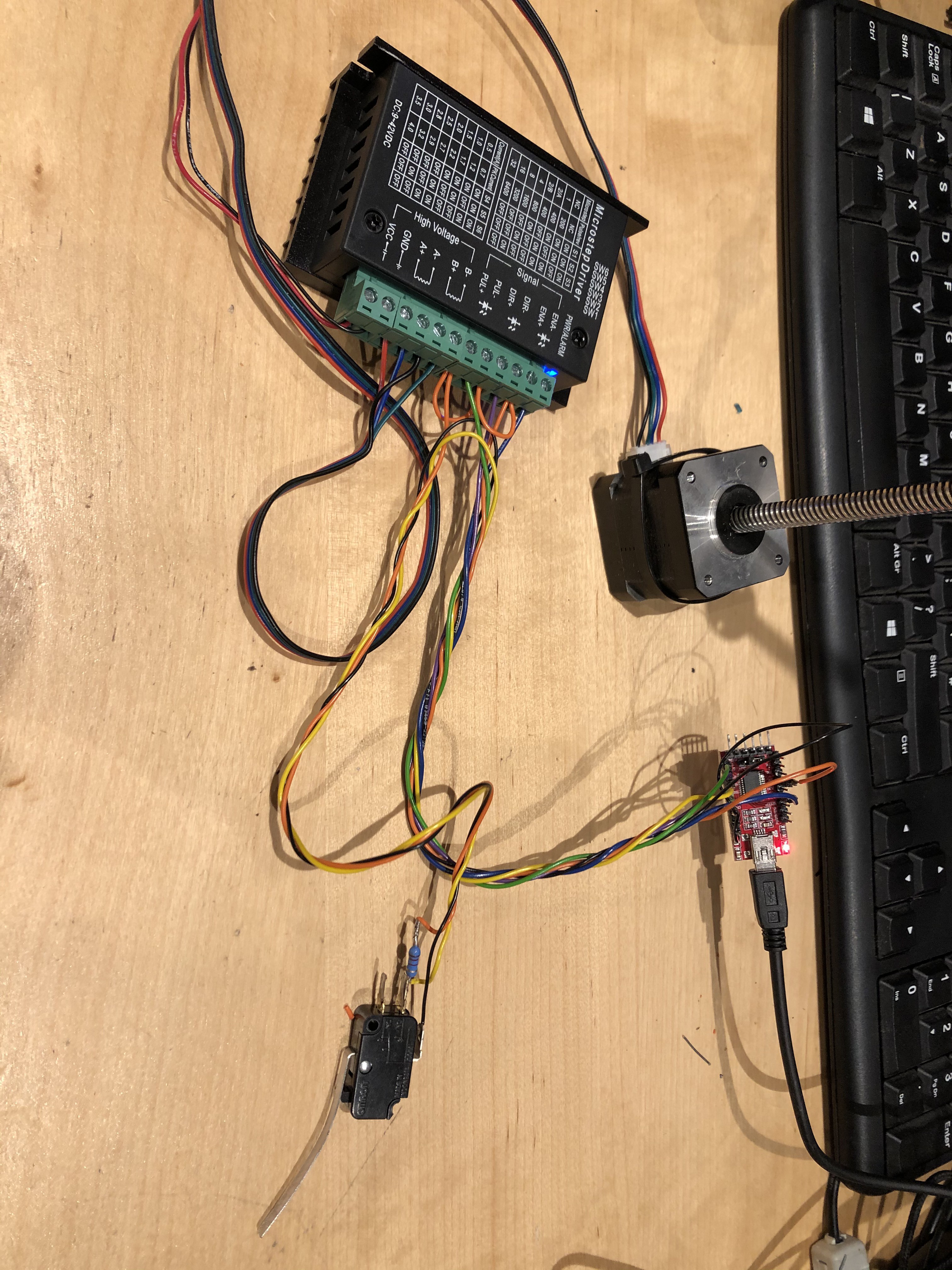
Here's a high-def photo of the setup. With some care you can make out the connections. But really, just look at the schematic, that is what it is for.
![]()
-
Controlling steppers
10/04/2020 at 18:26 • 0 commentsIn this project log, I'm going to share with you a new method for easily controlling a stepper motor, which I haven't seen anywhere else before, and definitively falls into the "hack" category, in my mind.
Alright. In my previous blog, I already mentioned that a stepper motor requires a pulse signal to change position, and a direction signal to change direction. How can we easily and cheaply do this with a computer?BTW: originally I wanted to use a microcontroller to move the mirror, but when I revived this project, I decided I would rather make it much easier for someone to copy and use my project and tinker with it. Also, when things are running on a computer, it is just so much easier to log data and to configure the system.
So how can we do this cheaply with a computer?
First of all, National Instruments have come out with the community version of Labview. If you haven't been in touch with labview before; it is a way to visually create programs. Even though I know how to program C for microprocessors and also C# on the computer, in my mind nothing beats Labview to quickly create a program with a nice looking Graphical User Interface.
You can download Labview community version from here:
https://www.ni.com/en-gb/support/downloads/software-products/download.labview.html#343639
Normally, Labview costs several thousands of dollars, but luckily the community version is free for non-academic and non-commercial use. On the flip side: the free version doesn't allow you to compile your program and run it on other computers, so you'll have to run it on the computer which you used to create the program.
Labview will be used to track the time, and control stepper motors which determine the mirror angles.
Secondly, to get the signals on the computer to the stepper motor drivers we are going to use.... serial port converters, also called UARTs, or USB-TO-RS232 converters.
That's right, we will use el-cheapo USB to UART converters to control motors. Normally, these converters are used to send serial characters, and we'll "creatively use them" to create motor pulses instead. In order to understand how, we'll have to dive a bit deeper into serial port signals.
https://blog.digilentinc.com/uart-explained/
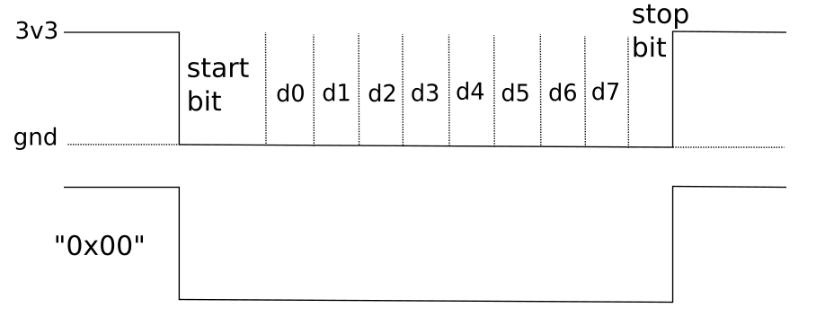
The signal below demonstrates what appears on the "TX" output of the USB-TO-UART. The signal level which is normally transmitted (no communication) is at 3.3V. When sending any signal, first the "start bit" is sent, which is a low signal with 1.5 X the time of a bit. A bit is shown as d0..d7. The baud rate is equal to 1/(bit length). The stop bit at the end is not really relevant for this purpose, it is also present to detect the length of the "frame", where a frame is everything from the negative flank before the start bit to the positive flank after the stop bit, and helps the receiver to detect the correct signal if the baud rate is not super accurate.
Because there are 8 bits (d0..d7), 256 values can be sent, which in hex represenation equals "0xFF". So if we send 0x00, we get the signal as shown... and that is going to be used as one motor pulse!
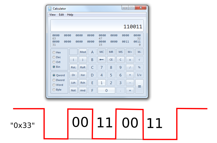
So it's super easy, by sending the character 0x00 via the serial port, we are sending once pulse to the stepper motor driver. That is sufficient for our purposes. But if you want the motor to spin faster, or if you cannot send the character 0x00 for some reason (because it's not a type-able ASCII character such as 0..9 and A..Z), you can use the character 0x33, which stands for the number 3 (http://www.asciitable.com/).
Let's type 0x33 into the windows calculator set to "programmer", and see what we get:
So by connecting the ft232RL to your motor driver, opening up your favourite terminal such as https://realterm.sourceforge.io/, opening the serial port on a baud rate of, say, 57k6, and typing in 3 on your keyboard, you tell the stepper motor driver to move 3 steps, or 3 times 1.8 degrees.
In our case, we also want to set the direction. Well, RS232 has several signals to control "handshaking". What is handshaking? The simplest form of RS232 has ground, TX for sending to the receiver, and RX to receive the answer back. But what if the receiver is busy at the moment? That is where the handshake signals come in.
https://en.wikipedia.org/wiki/RS-232
For instance, RTS stands for "Ready To Send", and is used to signal that the receiver is ready to receive something.
What is confusing is that it's sometimes the other way around, it all depends on which unit you define as the receiver, and which as the sender.
In any case, Labview allows you to control these signals. So by "setting" this signal, you can send another signal from your FT232RL to the motor driver.
Similarly, remember that limit switches were supposed to be used? We've got two actuators and thus two of those switches. By pulling up one terminal of a switch to 3v3 with a 10k resistor, and connecting the other switch terminal to ground, the resistor voltage will be high when the switch is not engaged, and low when the switch is engaged.
This signal can be connected for instance to CTS ("Clear To Send"), and can be read from Labview.
I'll post and discuss the entire schematic in the next post.
-
Positioning the actuators
10/04/2020 at 16:20 • 0 commentsIn my previous project log I described why I chose stepper motors. You can get them small, and couple them to a screw axis, but you can also be lazy (ahum, practical), and get stepper motors with long screw threads. You often see these types in 3D printers such as those from Prusa.
If you fix the brass (?) nut on the acme thread to something, it will move up and down depending on which way the stepper motor turns. You can see this in the example video below.
These actuators are becoming more and more affordable, and available second hand as well.
How to use them for the mirror
As you can see from the image and video above, the acme screw comes out of the motor and is not hermetically sealed. The plan is to use the solar mirror outside, in whatever weather. So we don't really want rain to come inside. To give the motor some protection, it should be mounted upside down. Any water which miraculously splatters inside can then drip out with gravity.
And if we mount the motors underneath the mirror, then the motor is more protected from rain; the mirror will be a little roof.
But, this does mean that the brass nut has to be mounted quite a distance from the ground, otherwise the end of the rod will hit the ground at some angles.
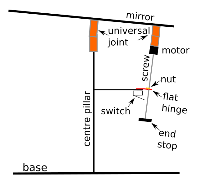
Hopefully the picture above will make this a bit more clear. The centre pillar does not change its length, but has the job of supporting the weight of the mirror. It has a universal joint (called universal hinge , which is a special hinge which can bend in two directions.
Both the motor and the centre pillar have to be mounted with a universal joint. Why? Well for the centre pillar this should be obvious: the mirror has to rotate in all directions. Originally I thought the motor could be mounted with a flat hinge, to constrain the angle only in one plane. But this is the disadvantage of designing in one plane only: I forgot that this joint also has to be able to rotate in all directions, because the mirror tilt! Oops. I found this out when I was constructing the actual prototype.
The task of the flat hinge at the bottom is then to hinge only in one plane, AND to constrain the lead screw of the actuator so that it cannot hinge in the other planes. I haven't quite figured out yet how I would do this easily.
The image above is only shown from one side, with one actuator. But in reality, there will be another actuator, perpendicular (90 degrees offset) from this picture (coming towards you from the screen).
So when the stepper motor rotates, the screw turns, and the nut moves up and down the screw. Because the distance between the nut and the mirror becomes longer or shorter, the angle of the mirror then changes.
Also shown is an end stop, which prevents the nut from falling off the screw when the screw is extended too far, and a switch. The switch is pressed in by the end stop, and this switch is present in the system for two reasons:
1) to know when to stop driving the motor, because the end stop has been reached
2) to know what the zero point of the system is. This is required as a place to start counting motor revolutions from.
In order to automatically (re)calibrate the mirror angle, you just keep driving the motor and rotating the screw until the end stop switch is engaged, and then you call that zero. This is a method commonly used in 3D printers.
Plenty of room should be left between the base and the lower platform, so that at all full extension, the end stop does not touch the ground.
Coming up soon: how are we going to drive all of this? It is supposed to be easy?!?
-
Selecting actuators
10/04/2020 at 16:15 • 0 commentsAn actuator is a fancy name for something you can use to create movement. A motor belongs to this group of things.
A long time ago, I had planned to buy loose DC motors, and connect them to screw threads with a coupler. But I'm running a bit low on time, and also, I'm trying to make this project as easy as possible, so I'm not going to use DC motors, but stepper motors. What is the difference?
DC motors require DC current to turn clockwise or counter clockwise, obviously using opposite polarities. A DC motor has one winding with two wires coming off. This means that when you for instance have a 12V battery and 12V DC motor, connecting +12V to one of the two wires coming out of a DC motor and connecting the other wire to the negative battery terminal, the motor will spin one way. If you reverse the connections, connecting 12V to where you previously had the negative terminal, then the motor will spin the other way. Here's a video of how this works:
Stepper motors, in their most usual (ebay purchaseable) configuration, have two windings, and the magnets inside the motors are configured intermittently between the two windings, so that when rotating the motor axis, there are lots of little steps where the motor has a natural resting point. By energising first one winding and then the other, the motor can be turned. This is a very roundabout way of explaining how it works, you should really have a look at this video:
So why not using the DC motor?
1) required end position. If you drive a DC motor repeatedly on/off for instance in 100 millisecond intervals, you can make it turn a specific angle. But this angle is far from precise. How large this angle is depends mostly on friction, counter force in terms of weight, and temperature.
For instance. Let's say you want to move the mirror by 5 degrees, and require the pillar a to extend by 5 mm. You can very accurately measure how long your time pulse needs to be in order to move 5 mm, but if you come back the next day and it is colder, the motor may find it harder to spin. And if you want to move it 5 mm in the opposite way, spinning may be difficult, because gravity is helping you to tilt the mirror down. (It really helps if you have read the previous blog).
So when a DC motor is used, ideally you need a sensor which measures either the length of pillar a, or which counts rotations for pillar a. This adds quite a bit of complication, because then suddenly we have to measure, which could require an analog to digital converter, or a digital counter. It would be nice if with every 'pulse' you apply, you knew exactly how much the angle change was......
The stepper motor
In comes the stepper motor. Typically, stepper motors are configured to change the motor angle by 1.8 degrees. A full circle has 360 degrees, so when you apply 200 steps in one direction, you move a full circle. For the sake of adjusting the mirror angle here, that's plenty accurate.
You have to know how to apply the steps to the two windings, but luckily there are drivers which take this work out of your hands, and they require only two signals: "move a step", usually called something like pulse, and "direction", usually called dir.
stepper motor driver For instance, on the cheap motor driver shown above (and there are many shops which sell this type), the signals are called DIR and PUL. There is also an enable signal EN, but that just tells the motor driver to listen to what you're saying on the DIR and PUL inputs. The two motor windings are connected to the A+/A- and B+/B- outputs, and finally you need to provide a DC voltage between 9-40 VDC, and set some switches so that you don't burn out the motor and configure microstepping. Microstepping tells the driver that for instance the motor only changes 1/32nd of a step per step, so that the resulution is now not 200, but 200*32 steps, and the motor is kept somewhere between its natural step.
So this was a bit of a detour. Why was the stepper motor better again?
When you apply a fixed time pulse to a DC motor, you never know exactly where it will end up, but you know exactly where a stepper motor will end up. As long as the stepper motor can move of course. If you provide too much counter force, then it obviously doesn't move and then you get "missed steps". So assuming that's designed properly, with a stepper motor, as long as you've been counting your steps over time, you will know exactly where you are.
-
Rejigging the jig
10/04/2020 at 15:10 • 0 commentsThe primary goal of the mirror is to reflect the light which shines somewhere where you don't want it to somewhere where you do want it.
There are plenty of solutions for this, and I just wanted to do it slightly differently. Not sure if it's better or worse. That all depends on the situation as well, doesn't it?
Objective #1 I want to make this setup as easy as possible to create/manufacture by someone at home (with simple tools), and objective #2 easy to source components. This may mean that some components could be cheaper if you did it differently, but then it would defeat objective #1 or #2.
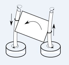
Below you see my original plan. There are three screw threads, and by rotating them, one of the three corners moves up and down.
![]()
The idea is shown below; the two round things at the base represent motors, and by spinning them clockwise or counterclockwise, the screw at the end of the mirror moves up and down, rotating the mirror counterclockwise (for the viewer). This image only shows two screw threads to make it simpler to understand, but in reality there has to be a third leg otherwise you can only rotate in one plane.
But there are problems with this. When the mirror changes angle, the horizontal distance between the legs becomes larger or smaller. And there are several ways in which this can be solved. The first way is to change the angle of the screw threads, as shown in the photo at the top of this log. The second way is to allow the screw threads to bend, as shown as in the diagram directly above. I suppose there are more ways, but that's beside the point.
This all comes down to constraints. A constraint is essentially preventing movement in a plane. For instance, bicycle pedals can freely move in the vertical and forward-backward plane, but not in the horizontal and left-right plane. They are constrained to rotate in one plane only.
The problem with the first way is: if the angle of the screw threads is allowed to change in any direction, the mirror can rotate around its axis and/or otherwise become really unstable, as shown by this impala calf video:
I like that the second way is very elegant: the screw threads bend gently, similar to bamboo. But in reality, this would be quite difficult to get right; if the screw thread is too thin, the bend would be too strong, leading again to collapse or unpredictable mirror angles. If the screw thread is too thick, it would be too hard to bend, and the motors would have to do a lot of work.
In example 2, the constraints in all directions is supposed to come from the exact springiness of the screw threads, and that's hard to get right.
So solution 1 it is, BUT, the movement of the 'pillars' is constrained to specific directions.
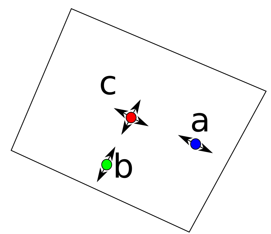
SOLUTION 1
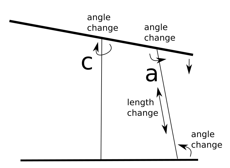
The picture below shows the concept. There is a central pillar 'c', and two pillars 'a' and 'b'.
The angle of pillar a is only allowed to change in the direction indicated by the arrows. The angle of pillar b is only allowed to change in a 90 degree angle (perpendicular) to the angle of pillar a, and pillar c is allowed to change in any angle.
The length of pillar a and b is allowed to change, but not the length of pillar c. To further illustrate this, please see the image below.
By reducing the length of pillar a, the right side of the mirror tips down, which changes the angle of a in respect to the base and the mirror, and also changes the angle of c. A bit hard to draw in 2D, but the angle only changes in this plane. And I've exaggerated the angles of pillar a a bit.
If you do the the same for pillar b, then you can tilt the mirror both in the a direction and the b direction.
If I've lost you by now, it will make more sense when I finally get a prototype and video. I hope that I have enough time until the deadline...
How to create these constraints? I'm thinking about using hinges for now.
Reflecting the sun into your home
My home doesn't face the sun, so it's dark and cool inside. I want to use mirrors to reflect sunlight into my home.
 That's right, we will use el-cheapo USB to UART converters to control motors. Normally, these converters are used to send serial characters, and we'll "creatively use them" to create motor pulses instead. In order to understand how, we'll have to dive a bit deeper into serial port signals.