-
Crunch time starts!
09/15/2020 at 17:02 • 0 commentsThe observant reader may have already noticed that this project has been on the back burner for several years. That's a characteristic of mine I'm slowly getting to accept and embrace ;).
I can get super enthusiastic about ideas and then loose interest with the drop of a hat. Or one project turns into another because for the first project I need to make a tool, and then I'm completely consumed with making this tool.
Anyway. I'm back on this project, and the hackaday price hopefully gives me the imputus to come to a more finished version of this project.
Since the last log, I've come to some different insights on various fronts.
1) stepper motors are a really easy way of precisely driving gears and shafts etc.
2) My original idea of using three screws to hold up the mirror technically works, and I like the idea because it would look vaguely organic, but there's a more straightforward way of doing it which I'm going to pursue.
3) Because I'm hoping to make the project super simple so that by following my instructions, any vaguely technical person could reproduce this project. So I'll probably not use a microcontroller and battery power, but rather use a computer and a long cable. There are some more advantages to this approach, which I'll spell out along the way, such as plotting the data etc.
By making it super simple, it should also have a better chance to actually make the deadline :)So watch this space.
-
Final bits
04/12/2015 at 15:50 • 0 commentsOk we need some way to detect how many rotations the shaft makes, a CPU board, and a Real Time Clock (RTC). We should have some Flash memory as well to store our data points.
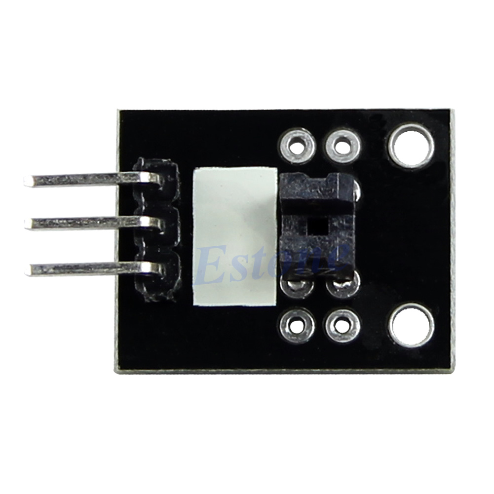
Photo-Interruptor Circuit
An easy way of detecting shaft rotation is by using a photo interruptor circuit, cost £0.99.
It works by having a LED (light emitting diode, usually infrared), and an opto-transistor. The transistor conducts depending on how much light falls on it, coming from the LED.
![]()
By inserting something in the slit between the LED and the opto-transistor, the output changes. I have no idea what type of transistor they put on this PCB, so assume it's just a simple transistor, without any schmitt-trigger capability. It doesn't matter in the end anyway. It'll work whatever is sent (famous last words...).
Processor Dev Board
Usually with low power requirements, I would grab an MSP430 processor, because they are usually the least power hungry processors around. However, finding a cheap dev board is expensive :(
Basically, I'd like to choose something cheap & simple & easy to obtain, so people can copy this project.
In the end I came up with Arduino. I've never used it before, so let's plunge into the deep.
A mini Arduino board (£2.24), which looks pretty, but has no programmer.
![]()
![]()
![]()
I also came across this one that seems to have a programmer already, or this one.
I must admit that I've bought the three mentioned dev boards, just so I can have a look at how well they perform. £2 for a dev board is a good price I must say.
The ATmega328P (large PDF!!) on this development board provides the following features:
- - 4K/8Kbytes of In-System Programmable Flash with Read-While-Write capabilities,
- 256/512/512/1Kbytes EEPROM,
- 512/1K/1K/2KbytesSRAM,
- 23 general purpose I/O lines,
- 32 general purpose working registers,
- three flexible Timer/Counters with compare modes,
- internal and external interrupts,
- a serial programmable USART,
- a byte-oriented 2-wire Serial Interface,
- an SPI serial port,
- a 6-channel 10-bit ADC (8 channels in TQFP and QFN/MLF packages),
- a programmable Watchdog Timer with internal Oscillator,
- and five software selectable power saving modes;
- - The Idle mode stops the CPU while allowing the SRAM, Timer/Counters, USART, 2-wire Serial Interface, SPI port, and interrupt system to continue functioning.
- - The Power-down mode saves the register contents but freezes the Oscillator, disabling all other chip functions until the next interrupt or hardware reset.
- - In Power-save mode, the asynchronous timer continues to run, allowing the user to maintain a timer base while the rest of the device is sleeping.
- - The ADC Noise Reduction mode stops the CPU and all I/O modules except asynchronous timer andADC, to minimize switching noise during ADC conversions.
- - In Standby mode, the crystal/resonator Oscillator is running while the rest of the device is sleeping. This allows very fast start-up combined with low power consumption
Power Consumption at 1MHz, 1.8V, 25C
- Active Mode: 0.2mA
- Power-down Mode: 0.1µA
- Power-save Mode: 0.75µA (Including 32kHz RTC)
And look, active mode 0.2 mA. Far below what I guestimated for current use (1 mA). The batteries are going to be fine!
Sorry for the large amount of text, but all in all, this processor has got everything that we need; EEPROM to store our desired strut lengths, an ADC for measuring the photo-isolator, plenty of output pins, low power, and an RTC. Hmm Atmel says it has an RTC, but what they call RTC is not a Real Time Clock, but a Real Time Counter. Not sure if that'll work. We will see.
Anyway, I've ordered all the required components, now I have to wait for a few weeks for them to arrive :S.
-
Battery Time!
04/12/2015 at 14:26 • 0 commentsOkay, so we've got three motors, three H-bridges, and a Step-up converter. So we've got the motor side of things covered. We'll discuss measuring the motor rotations, measuring light levels, and choosing a CPU dev board later.
I'm just going to steam on as much as possible, because I'll have to wait for up to a month now anyway for parts to arrive from China (I hope they arrive).
-------------------------------------
Calculated Current Usage
-------------------------------------
We need a battery to power everything. A solar powered self recharging one of course.
Motor control:
Let's say, 6 hours, twice per hour, 10 seconds, at maximum power of 100 mA @ 12 VDC: 200 second at 12 VDC, at 100 mA. so we need 200/3600 * 100 mA = 5.56 mAh.
The step up converter wastes 10% of it's power, and let's give the H bridge also 5% wasted power.
So we need to multiply the required motor run energy by 115%: 6.38 mAh.
Basically, we can just ignore this number. If it's not sunny, we're not going to bother changing the motors. If it's sunny, the built-in solar panel could easily recharge this feeble amount of energy usage.
Now, hopefully we can get a CPU dev board that can run on 1 mA standby power. That shouldn't be too hard, really, they should easily outperform that.
Let's demand that it will keep running for one week without ANY light. I know, it's not realistic, but hey, we're doing worst case.
That's 1 mA * 24 hours * 7 days = 168 mAh.
So we're looking for a solar recharing battery with 168 mAh, that puts out 5 VDC.
Ebay to the rescue!!
--------------------------------------------------------
Finding the right solar charging battery
--------------------------------------------------------
This is the cheapest I could find. £5.98
![]()
Solar panel:5.5V/80mA
Voltage Output:5.5V
Li-polymer Battery:1350mAH
Size:9.3*4.3*1.1cmI've actually used this thing before and it worked quite well. It is massively overspec'ed for what we need, which is good.
However, we can also make it more difficult (= interesting) for ourselves, and save some money (hopefully). Why not build our charger ourselves?
-----------------------------------------------------------
Building Our Own Solar Charging Battery
-----------------------------------------------------------
We can just buy a separate solar panel ( 5V, 40 mA, £1.09) and 4x1.2 Vdc NiMH batteries? (1000 mAh, £1.09)
![]()
![]()
But, mime, the battery voltage adds up to 4.8 VDC, and the solar panel adds up to 5V, aren't you worried about exploding batteries?
From a 5V,40 mA = 0.2 W solar panel? No. That amounts to 40/10 = 0.04 C of charge, which is equal to the advised trickle charge to keep them topped up.
How about self discharge? See above argument.
How about discharging too much?? Hmm perhaps. Let's see what happens.
Apparently, you have to stop discharging a NiMH at 800 mV. At 4x 800 mV, this would be 3.2 VDC for the entire pack. This is something that the step-up converter could still work with.
So to prevent that, we need a discharge protection circuit, with a cutoff voltage of 3.2 VDC. Let's see if Ebay has them.
-----------------------------------------------------------
Over Discharge Protection Circuit
-----------------------------------------------------------
There are plenty of cheap Li-ion protection circuits, for instance, this one, at £1.51.
- Charging voltage DC3.7V, Low voltage, over charge, over load protection.
- Charging for single battery or few battery in parallel, Suitable for Multi-cells form DC3.7V, such as Oppo A100 A113 A115 A121 A127 A520 cell phone.
- Charging limit voltage is 4.2V, Battery capacity is 900mAh.
Our battery is 1000 mAh at 4.8 V, so that fits. We don't have to be fully charged. This protects the batteries, but limits the use to 3.7-4.2 VDC.
However, they don't mention the minimum discharge voltage limit, and that is what this is all about. So we can't really use this after all.
----------------------
The Showdown
----------------------
So. Have we made it cheaper by buying our own solar panel and batteries?
The all-in solar charger was £5.98, and the custom hacked solution
£1.09 for the solar panel
£1.09 for the NIMH batteries
£0.99 for battery holder 4x AAA batteries
That amounts to £3.17, so roughly half price, but without under voltage protection.
How much danger is there from undervoltage?
1000 mAh, 1mA current use (worst case), then discharge time = 1000 hours, or 41.67 days.
And we've put in a solar panel, which works even during the day. If we have full sun for only half an hour per day, then the current use of that day is accounted for.
So let's live dangerously, and go for the cheap Mac-Gyver option! This is hackaday.io after all.
We can always buy the more expensive option later.
What do we need still? a motor revolution sensor, a Real-Time-Clock (RTC), and a CPU dev board (low power).
-
Controlling the motors
04/12/2015 at 13:23 • 0 commentsOkay, we've found a motor, and a step up converter to provide power to it. Now we need to control it.
A linear motor has two terminals, + and -.
If you apply a suitably high DC voltage between the two terminals, the motor will start rotating. + and - are chosen relatively arbitrarily, if you change the polarity it will rotate in the other direction (for a typical motor, sometimes it will only spin in one direction, such as PC cooling fans).
An H-bridge is a common way of controlling a stepper motor or linear motor. Let's have a look.
![]()
If you close S1 and S4, current flows from the 9 volts supply to ground, and the motor will turn one way. If you only close S2 and S3, the motor turns the other way. Easy peasy. The circuit looks a bit like an H, hence the name H-bridge. A real-world circuit will have transistors that act like switches, and some bits around it to support the circuit and control the transistors etc.
Quickly Batman, off to ebay!
We're looking for something that, again, can switch 12 VDC, and 100 mA in static current, and a bit more to deal with start current (of the motor), which can be significantly higher.
£1.57
![]()
Features:
L298N as main chip, ST corporation production.
Low heat,outstanding anti-interference performance.
High working power to 46v,large current can reach 3A MAX and continue current is 2A, power to 25w.
Can drive one 2-phase stepper motor, one 4-phase stepper motor or two DC motors.
Built-in 78M05,get power from drive power,however, when drive power over12V, please use the external 5v power as power supply.
Large capacity filter capacitance,afterflow protection diode, more stable and reliable.
Specification:
Double H bridge drive
Chip: L298N (ST NEW)
Logical voltage: 5V
Drive voltage: 5V-35V
Logical current: 0mA-36mA
Drive current: 2A(MAX single bridge)
Max power: 25W
This module has a built-in 5v power supply, when the driving voltage is 7v-35v, this supply is suitable for power supply
When ENA enable IN1 IN2 control OUT1 OUT2
When ENB enable IN3 IN4 control OUT3 OUT4I'm not in the mood to translate too many specs this time.
Something that is not useful in this application is that this board requires 0-36 mA of logical current (!!!!!).
Too much for typical boards, and unnecessary.
£0.99
![]()
My comments in cursive
- Feature: Onboard two the L9110S motor control chip
- the module can simultaneously drive two DC motors or a 4-wire 2-phase stepper motor. Cool, two for the price of one!
- the 800mA continuous current output capability per channel. Sufficient.
- Low static work current. How much??
- Each channel has 800mA continuous current output. Again? They must be impressed by this achievement.
- Low saturation pressure drop. This is Chinglish. What they mean is voltage drop.
- TTL/CMOS output level compatible, can be connected directly to the CPU. Hah! not really. What I found out here is that the input control voltage has to be the same as the drive voltage. That's fine though, we can in the aid of some external transistors as level shifters.
- Output built-in clamping diode, apply to the perceptual load. This is to protect the output stage of the H-bridge from inductive voltage surges.
- Control and drive integrate in IC
- Have pin high pressure protection function = overvoltage protection
Specifications:
- Working temperature: 0-80 ¡æ
- Size:29.2(mm)x23(mm)
- the module input voltage :2.5-12V
- Power supply voltage: DC2.5-12V
- Net weight: 6g
- Package weight: 16g
- Package includes: 1 x L9110S H-bridge Stepper Motor Dual DC motor Driver Controller Board
They are being a bit cheeky here, because they make it look like you can control the motor with 12V and the inputs with 2.5 VDC. But that is not the case.
In case anyone is interested, here's the datasheet of the IC on this module.
Anyway, let's just buy them, they do the trick. I just need two, because each has two H-bridges.
-
Step Up Convertors
04/12/2015 at 10:50 • 0 commentsStep-up converters (or boost-converters, although I like the first title because in my mind it more accurately describes its function), create a higher DC output voltage from a DC input voltage.
In my case, I'd like to have 12V output, at 1.2 W, which translates to 100 mA output current. More is welcome, but only if it's a cheaper module.
Oh, and I probably am going to use a solar rechargable battery pack, which puts out 5VDC.
Let's have a look at a step-up converter that fits the bill.
![]()
I'll put my comments in cursive.
This looks like a nicely layed out board. Plenty of space between components, each component has got a reference designator (R103 etc), although not very clearly, and the input pins are labelled, power traces are made thicker than others, so this is put together with at least some care. That's a comforting thought.
Description:
Input voltage 3 ~ 6V, output 12V (deviation +-5%)
Okay, nice low starting voltage, and we can use 5V.
Maximum input current: 1.5A
That's a bit odd because they only mention 1A further below. But that's fine.
Long-term work Current: 1A.
Much more than we need. Good.
Conversion efficiency : 90%
Very good, I've seen far worse (especially for chinese dev boards)
PCB size : 25MM x 15MM
Start Voltage 2.8V, Output Current 50MA
INPUT 3V 1A; OUTPUT 12V 220MA
Okay this is already more than we need for one of our three motors, and we're not going to drive them all together, I imagine.
INPUT 5V 1A; OUTPUT 12V 370MA
Fine, this can drive 3 of our motors simultaneously.
INPUT 6V 1A; OUTPUT 12V 450MA
This is with on/off switch voltage boost module.The master chip is FP6291GLR,for more Details,click here!
That would've been nice if click here were actually a link, which it wasn't. I've managed to find it here. It's a step up convertor indeed, with a power down current of 0.1 uA, which is good for our purposes. Also, it has adjustable overcurrent of 0.5-2.5A, which is good for us too, if we set this to 0.5A it will limit motor dissipation to 6W, and possibly protect the gears if one of the threads jams.
Can used the input voltage (VIN or GND)control the switches,also use MCU IO control the switches.
This means that we can control the functionality (enable) with a voltage anywhere upto VIN. In reality the minimum enable voltage is 0.96 VDC, which indeed is something most MCUs can do.
Control current is very small, MCU IO port can be directly controlled. Including micro-controller : ARDUINO UNO MEGA2560 AVR STM32 ARM PIC AT89C51 STC MSP430 FPGA CPLD etc.
This is info for noobs.We're above that, surely?
When the EN pin = GND(OR MCU LOW level),the boost module is working properly;
When the EN pin = VIN(or MCU HIGH level,3.3V/5V) OR Not Connected(or MCU High impedance), the boost module into standby mode, stops working, the output voltage is 0V (Can measure the output voltage is 500~800MV, which is inductive output voltage, you does not have to bother).
Okay, I'm glad we does not have to bother. I'm not sure with what we don't have to bother with? In any case: what is meant here is that the module is enabled if it's pulled to ground, otherwise it's in standby. That's fine, we can just use a simple NPN transistor to pull this pin to gnd. Also, and this is important, it looks like when the module is disabled, it cuts out the output voltage to 0.5-0.8 MV (do they mean 0.5-0.8 V???). In any case, some step-up converters just pass on the input voltage directly to the output when the module is disabled, in that case our motors may still be powered. So it's all good.
Applications:
1.Battery powered equipment, 2.Wirels mouse, Wireless keyboard 3.Toys 4.Camera, Video camera 5.VCR 6.PDA 7.LED Lighting 8.Wireless communication equipment 9.MP3/MP4 player 10.Audio equipment
Well they have a very large imagination. Who wouldn't want to power their wirels mouse? They should include "solar powered heliostat". Perhaps I should email them.
Package listing:
2 PCS 5W With ON/OFF EN Switch DC3-6V To 12V Step-up Boost Converter Power Module
These modules will do the trick, in fact, I only need one of them, the other one will be put in the spare parts drawer.
Now we need an H-bridge for the motor.
-
Finding a Suitable Motor
04/12/2015 at 08:54 • 0 commentsIn my last blog it was determined that the motor should ideally be faster than 400 RPM (for the impatient among us), and have a torque of 0.0115 N.m.
In DC motor language, 0.0115 N.m is equal to 118 g.cm, calculated using this app.
On ebay (my N# 1 place to go to), manufacturers are actually bloody negligent in adding information about their motors.They hardly ever mention the current usage of a motor (even without load), and if you're very lucky they'll mention torque.
The three most important factors that influence my choice of motor are:
- speed (rpm)
- torque (N.m, g.cm, ...)
- cost.
Basically, it all boils down to the motor power, which translates into torque and speed. Higher motor power: higher speed or torque. Cost is a factor as well, given that I don't want to spend more than approx £7.5 per motor.
Here's one geared motor in which they helpfully specified torque, and even current! :)
4300RPM Rotary Speed Vibration DC Geared Motor 16.8mN.m Torque 24V
Rated Voltage DC 24V Speed 4300 RPM Current 0.05A Torque 16.8mN.m / 172g.cm Gearbox Size 56 x 33 mm/ 2.2" x 1.3" (L*D) Ok, torque: 172 g.cm. Check. (I hope this is correct).
4300>400 RPM. Check
£4.74 < £7.50. Check.
24 VDC drive voltage. Hmm. That's a bit more tricky. 6V or 12V would be easier. But with these motors, usually they start working at a much lower voltage anyway. And 1.2W of electrical power is not very hard for a step-up converter to source.
They didn't really specify motor volume in this case. I think in this case, what is meant with "gearbox" is: "The entire thing, gear box including the motor".
As for the "Vibration" part of this motor listing. I assume they are just trying to help me come up with possible uses...
Double check to see if same-ish motor has same-ish torque-speed product:
- Torque: 2.0kg cm
- Voltage: 12V DC
- RPM: 30RPM
- Diameter (top section): 40mm
- Diameter (body): 32mm
- Height (excl. shaft): 33mm
2000 g/cm @ 30 RPM = (2000*30) / 4300 @ 14 g.cm (calculating back to the first motor)
Hmm that's a factor 10 off. Oh dear.
Rated Voltage: 12V
Speed: 70 rev / min
Resist twisting: 7Kg/cmmotor volume: 30x20 mm
Assuming that "resist twisting" is actually the torque:
So that's 70 RPM * 7000 g/cm / 4300 = 114 g.cm.
Okay so this one has a slightly lower motor volume than motor candidate N#, but only a factor 2 off in torque. That verifies N# 1 somewhat. (actually, the torque for this one is exactly what I need for my mirror project. However RPM is a bit low).
Okay, so we could use that motor #1, but lets see if we can find one with a similar or larger motor volume, and lower price, and preferably lower driving voltage as well.
There is :
360-900R/min, 12v, 60x30 mm (L*D) £3.90
- Used in electric shaver, pager, and vibration toy.
(I don't know why they say 360/900R/min though. Under load? What load? Different voltages?)
... aaand that was about all I could find on ebay, everything else was more expensive or had worse RPM figures.
However, the last one seems to be exactly what is needed for this project.
![]()
The power was not rated in this ebay ad, but it has a slightly larger body than the previous motor in which it was defined, so probably higher motor power. Furthermore, the RPMs are lower, so it should have at least the same torque as N# 1, but probably higher, and the voltage is 12VDC, which is manageable.
Although this picture shows a motor with a pinion wheel, the listing doesn't mention this otherwise, so I'll assume that they've just been a bit careless there and used a generic picture.
If this doesn't work, I could always use it for a shaver, pager, or vibration toy. Perhaps as a surprise to my girlfriend? Although, what would she do with a pager? (...)
Anyway.
Next item on shopping list:
Some power driving electronics.
Requirements: 12 VDC, 1.2 Watt.
-
Let's just do it and see where it ends..
04/10/2015 at 14:29 • 0 commentsI've thought a bit about the three strut construction, and how and why it would work. What it came down to was this: there are three axes of linear translation and 3 axes of rotation. If not everyone of these axes is constrained, structures will not be stable. That's why for existing heliostat structures we see something that, for instance, is fixed in the translation directions, and can vary in rotational directions. For instance, think of a big satellite dish, a common construction is one that can rotate around its base, and also in the vertical plane (also how many heliostats work).
However, I don't want to make such a structure. I'm intrigued by this structure. I want to see how well this would work. The trick is that instead of using universal couplings for all strut points, this structure is fully constrained by constraining the struts at the bottom. No X,Y, Z, or rotational movements allowed. (Well, except for one of course, in the horizontal plane.)
The mirror corners are constrained in X,Y,Z but in none of the rotations. The mirror will then be (loosely) constrained by the elasticity of the strut threads, M6 metric thread, which is fairly elastic. Basically, this structure is the inverted situation of what you would get if you hung a mirror from the ceiling with three ropes. The only difference is that gravity is not really acting as a stabiliser in this structure.
Will it be easily scalable to larger structures?
Not really, I'd say.
Will it be wind proof?
Well, let's say that it will behave more like a bundle of reeds.
Will it look elegant?
Well, I think so. All the active bits will be housed in the base, and the only thing that will be seen is the mirror, three struts, and a base.
Will the settings be repeatable?
Well, this was my fear before, that it wouldn't, but I decided that unless the M6 threads will be bent too much (beyond their rated stress), they will not permanently deform, and they will operate nicely in their elastic region. In that case it's just a play of the same repeating forces, so they should result in the same positions. I'll just have to make sure they're not bent too much. How much bending is allowed remains to be seen.
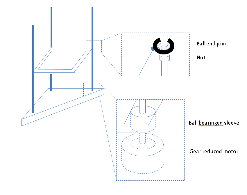
Construction
In the base there will be a ball bearinged sleeve*, 19 mm high, and underneath a motor with a gear reduction. The sleeve is there to prevent off-axis stresses on the motor. Motors don't like too much stress from unintented directions, just as humans.
When the motor turns, the M6 thread turns too, and the nut, which will be prevented from turning in some way, will move up and down. The ball end joint is only there for structural support, really.
![]()
I've taken some more measurements, and in the end it transpired that in order to catch sunlight in the morning the mirror is almost vertical. Hence the ball end joints. It all depends somewhat on the angle of the ball end joints on how extreme the angles can be. I have to be careful not to 'over tip' the mirror anyway (up side down), because that can destroy parts of the mirror once it starts moving in to the wrong angle.
What Motor Size and Rotation Speed?
M6 has a pitch of 1 mm, so for every rotation, the thread moves one mm. If the mirror has to be set every half hour initially, then the strut has to move up/down with about 7 cm. That's 70 mm. So in order to not wait for too long (less than 10 seconds, I'm an impatient man), the motor has to turn with at least 7 rotations/second, or 420 RPM.
The current mirror weighs about 2.5 kg, which is roughly equal to 25 N, assuming all the weight will be on one strut (which is not the case, but we're doing a worse-case calculation). The shaft is 6 mm in diameter.
I've used this nifty online torque calculator to calculate the torque required:
it's 0.0115 N.m for raising and -0.00354 for lowering (using standard friction coefficients).
So unless I've got a gear reduction motor or a brake, or if the motor is feeble in general, the struts are going to slowly lower themselves, which is not what we want.
... I'm off to find some geared motors on ebay.
* new words added to the English languague: bearinged, i.e. the state of being equipped with bearings.
-
Ponderings...
04/07/2015 at 20:00 • 0 commentsI'm thinking whether my construction of three struts will have repeatable results. Two of the struts (A/B) can change, and the third (C) is rigid.
There are 6 axis of freedom in general: up/down, left/right, forward/backward, and 3 rotations.
By having one strut rigid, but with a pivot point, I'm putting in constraints;
- C: forward/backward, left/right, up/down
- A/B: forward/backward, left/right, rotation around
All rotations are still possible; rotation around the C axis (vertical), rotation in up/down plane, and rotation in left/right plane.
Currently the stiffness of each strut is dependent on the length of the strut, and the mirror position is a function of the stiffness of each strut and friction (?) in the frame.
The rotation around the central axis of the mirror (defined by the point not supported by the strut and the point attached to strut C) is now depending on the stiffness of the flexible coupling and the length of the two struts.
Hmm.. I'm not sure about this design yet, because the next phase could be to replace all couplings by universal joints, which remove the spring action that the struts currently have.
However, by using rotating platforms etc this system becomes more defined but harder to set and control.
(to be continued)
-
Measurement 1
04/07/2015 at 17:19 • 0 commentsIntroduction
I wanted to get some data on how much the struts have to extend/retract during the day. So I made a cheap rig with a mirror supported by three M6 threads, A, B, and C.
Methods
The threads are threaded into a wooden base with some legs to keep the wood off the ground and the platform more stable. The wooden base is slightly smaller than the mirror, because that was what I had lying around. The mirror surface is 385x385 mm.
Threads A and B were about 500 mm long, and thread C was 1000 mm long (how I got it from the shop). I kept the mirror corner of strut C constant throughout the measurement, because that one is supposed to become my fixed pillar. I've added an image of the rig, so it will probably make more sense to you now.
![]()
Around noon I aligned the mirror so that it aimed at a fixed point on the wall, and then several times later, I re-aligned the mirror and noted how much extension each of the struts needed.
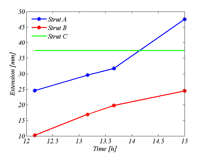
Results.
time A [mm] B [mm] C [mm] 12:11 24.6 10.2 38.3 13:11 29.6 16.9 13:39 31.7 19.8 14:56 47.5 24.5 ![]()
Strut A had the largest change of approximately 25 cm. I suspect that had I started taking measurements earlier, then I would have seen even more change. Strut B moved comparatively less with approx 15 cm.
The increase of strut B seems to be roughly linear, whereas the increase of strut B starts off more or less linearly but then becomes nonlinear.
The average increase of A per hour is approximately 5 cm/h until 14:00 and then increases to approx 14 cm/h. However, ideally I need to take more data points to verify this.
The average increase of B is roughly 6.5 mm/h.
At 15:50 the mirror was in the shade. I didn't get any early morning measurements, because I was still making the rig then.
Discussion
The length of the struts is slightly too short. Ideally for strut A, the strut length should be 10 cm longer. So for the next experiment I'll swap struts C and A around.
Strut A has a large change in length. That is good in regards to needing a less accurate position sensor. However, bad in regards to needing a larger sensor. Perhaps I'll have to consider a stepper motor or a position encoder on a linear motor instead of a parallel capacitive sensor. I could then measure the extension by counting shaft rotations.
Overall I was pleased to find that I could indeed keep C at a constant length.
M6 thread may be a bit too flexible. However, until I've got some universal or ball joints at the mirror corner points, that is quite helpful.
Conclusion
All in all, not a bad result for a first measurement.
-
sun tracking mirrors log
04/06/2015 at 18:06 • 0 commentsI've just come up with the idea.
Reflecting the sun into your home
My home doesn't face the sun, so it's dark and cool inside. I want to use mirrors to reflect sunlight into my home.