-
1IR SENSOR CIRCUIT
The battery used in the socket of the hand gives an output of ~7 volts. This supply is given to the voltage regulator LM2596S, which is adjusted (by calibrating the potentiometer) accordingly to give a constant output of 5 Volts.
-
2IR SENSOR CIRCUIT
We need 5 volts to trigger the relay switch VMA406 and the IR sensor QRE1113 (digital version). Placing the IR sensor on the prosthetic arm where the impact of the muscle movement is maximum, the output of the IR sensor (when the muscle is flexed the most) is fed to the relay switch
-
3IR SENSOR CIRCUIT
The circuit for the appliance such as a swatter or laser light will be put in between the NC and the common terminals of the VMA406 to act as a switch to turn on/off the circuit.
When the muscle is flexed the most, the IR sensor will turn off the relay switch (which is by default ON) and the squatter or the laser light is turned on and stays in that state as long the muscle is flexed. Once the muscle is relaxed, the swatter/laser light is turned off.
-
4SWATTER HACKING
Once you power the relay and the IR sensor turn on the power button on the swatter to test the circuit.
-
5SWATTER HACKING
Locate the power button in the swatter.
![]()
-
6SWATTER HACKING
Make sure that is turned off and dismantle the handle of the swatter
-
7SWATTER HACKING
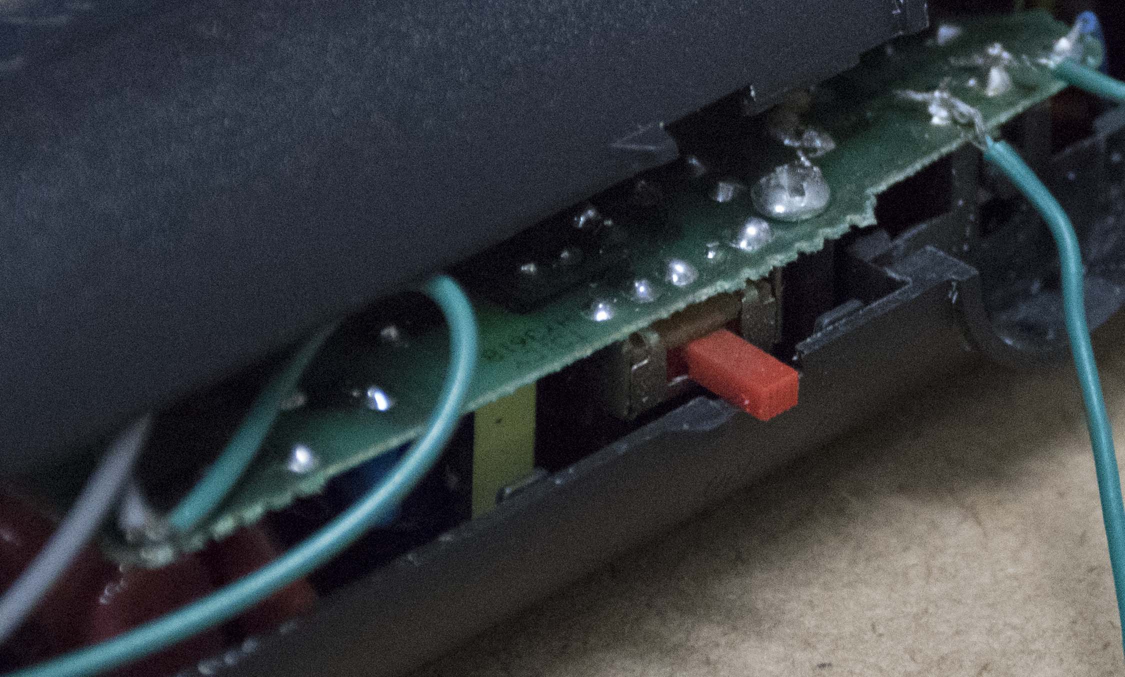
Locate the terminals though which the power source is given to the push button
-
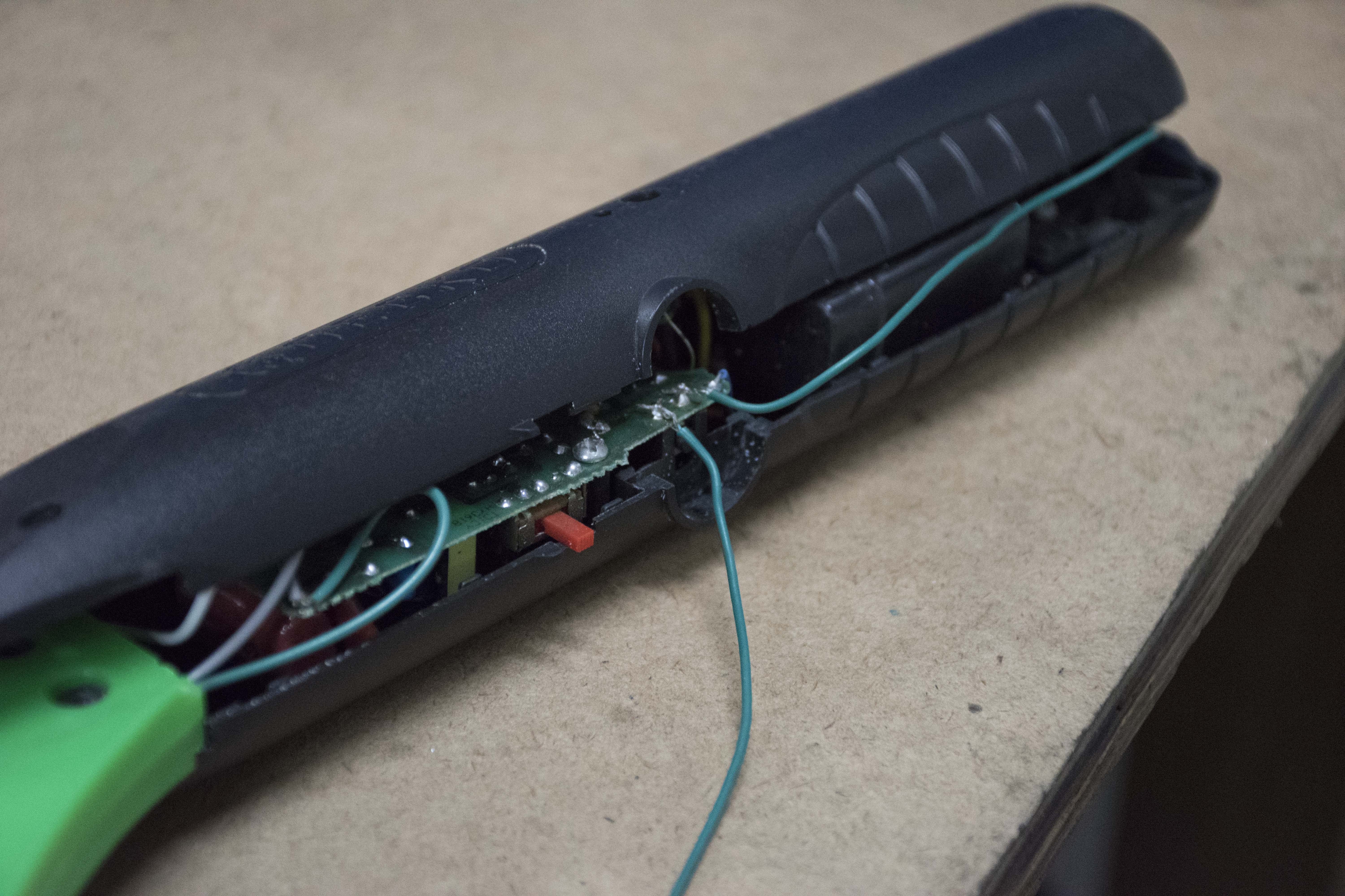
8SWATTER HACKING
Solder two wires to those terminals as shown in the picture
![]()
-
9SWATTER HACKING
Makes sure the wires do not touch the neck of the swatter while soldering.
-
10SWATTER HACKING
Assemble the handle making sure the ends of both the soldered wires are outside the handle.
Discussions
Become a Hackaday.io Member
Create an account to leave a comment. Already have an account? Log In.