techav
-
New Beginnings
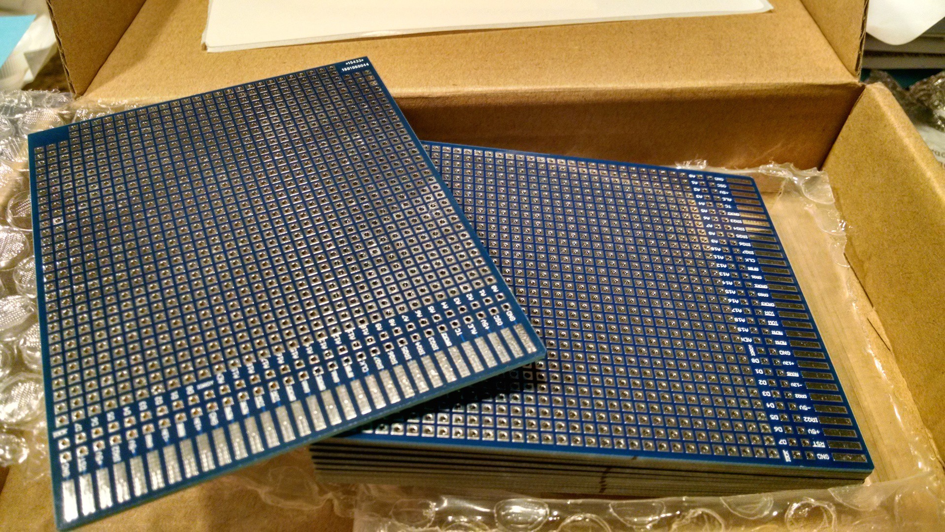
02/14/2016 at 18:39 • 9 commentsWell, I did it. I ordered my first custom circuit boards. I laid out a prototyping board with an ISA bus card edge, sent it to dirtypcbs, and after a month of impatiently checking the mailbox, they arrived.
![New boards!]()
![Temporary 2-slot testing backplane]()
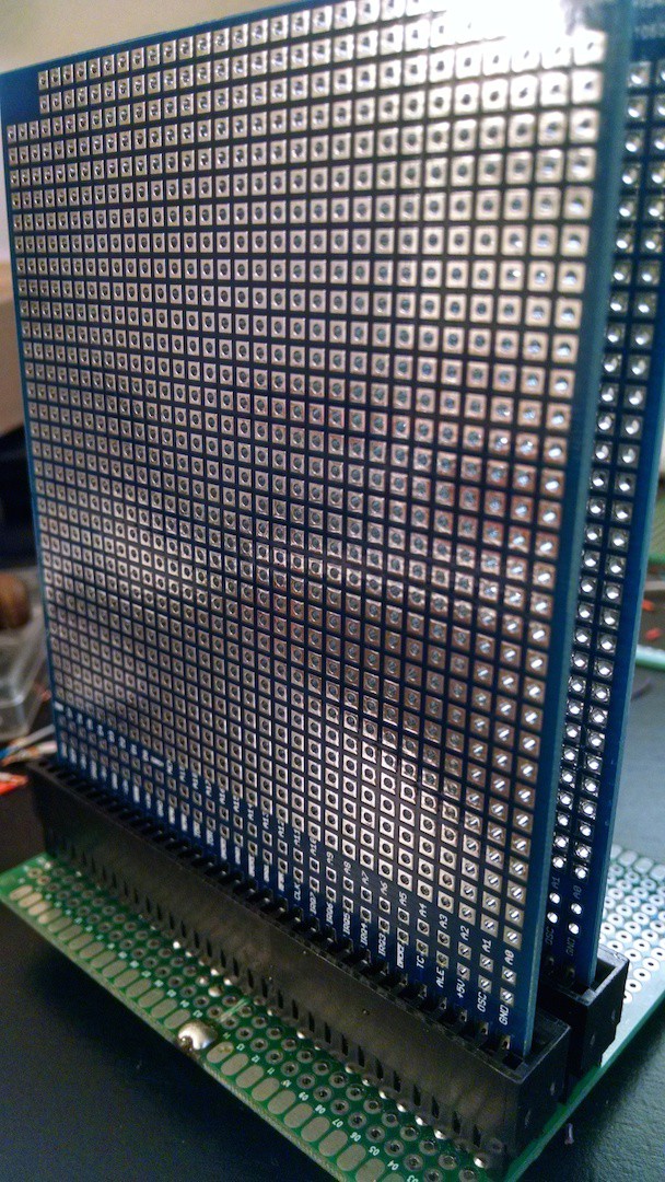
I ended up with eleven boards. After I've built a few and done some testing, my plan is to order a second set of boards to use as a backplane. I'm thinking around five card slots per backplane board, with right-angle headers on the ends to link them together. Until then, I've soldered a couple slots onto cheap China special protoboards, and one slot built as a breadboard adapter.
As for the computer design itself, I decided to keep the buffers on the address and data bus since I'm going with the card-based approach and have a full set of Z80 peripherals to experiment with. And after quite a bit of going back-and-forth on the matter, I've decided to go with convention for the Z80 and use the low byte of the address bus as the IO address, leaving the high byte as an optional parameter byte. This will give the full 255 possible IO devices (instead of just sixteen as in my previous design), and give up to 8 bits for device parameters (such as A/B and C/D select on the SCC, PIO, etc). I'm using a design I first saw [Jan Verhoeven] use for selecting I/O devices: 8 DIP switches set the address of the IO card, and the card address is compared to the address bus with a 74'688 equality comparator.
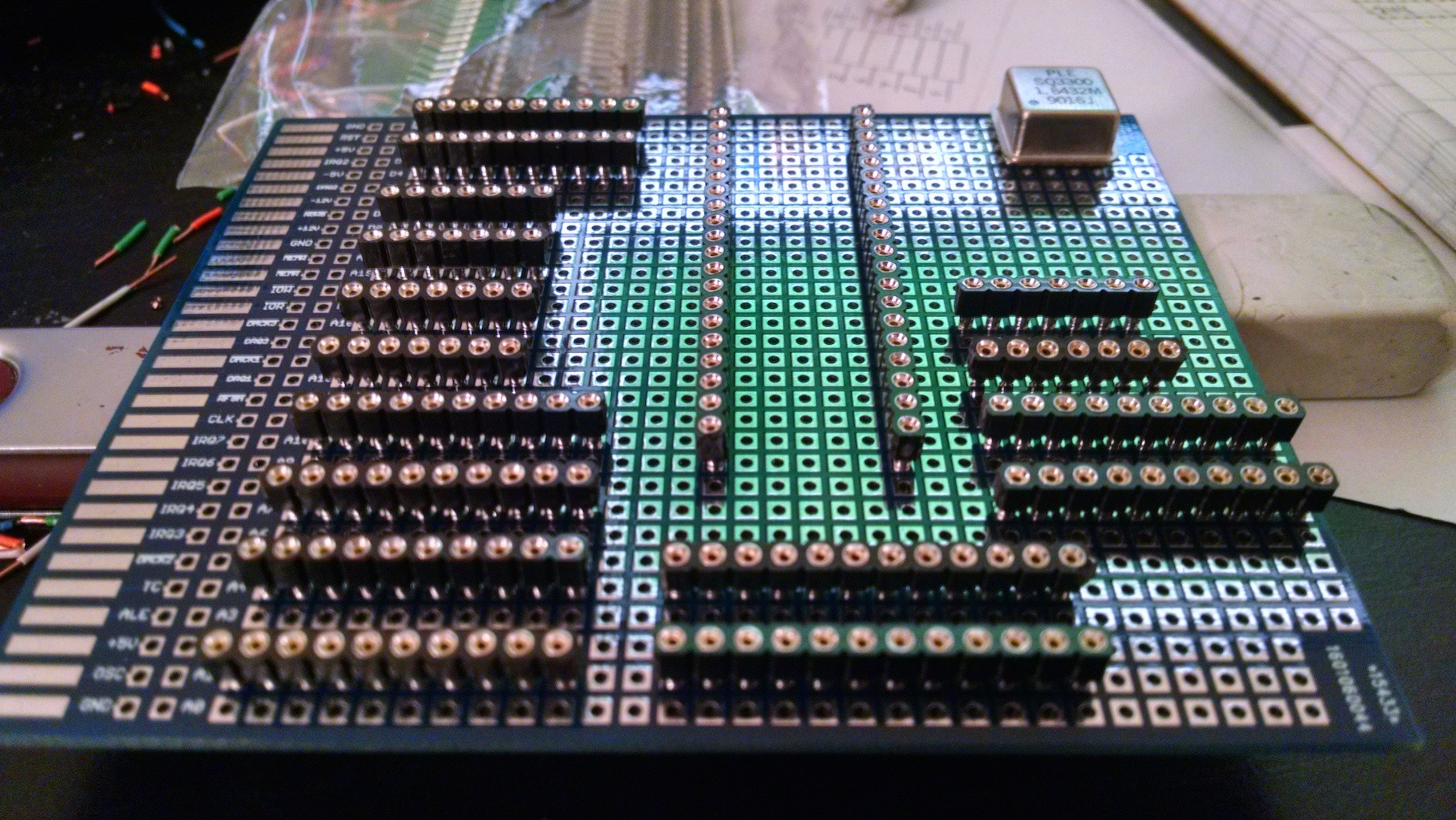
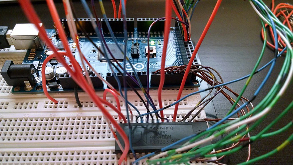
![Testing chip layout]()
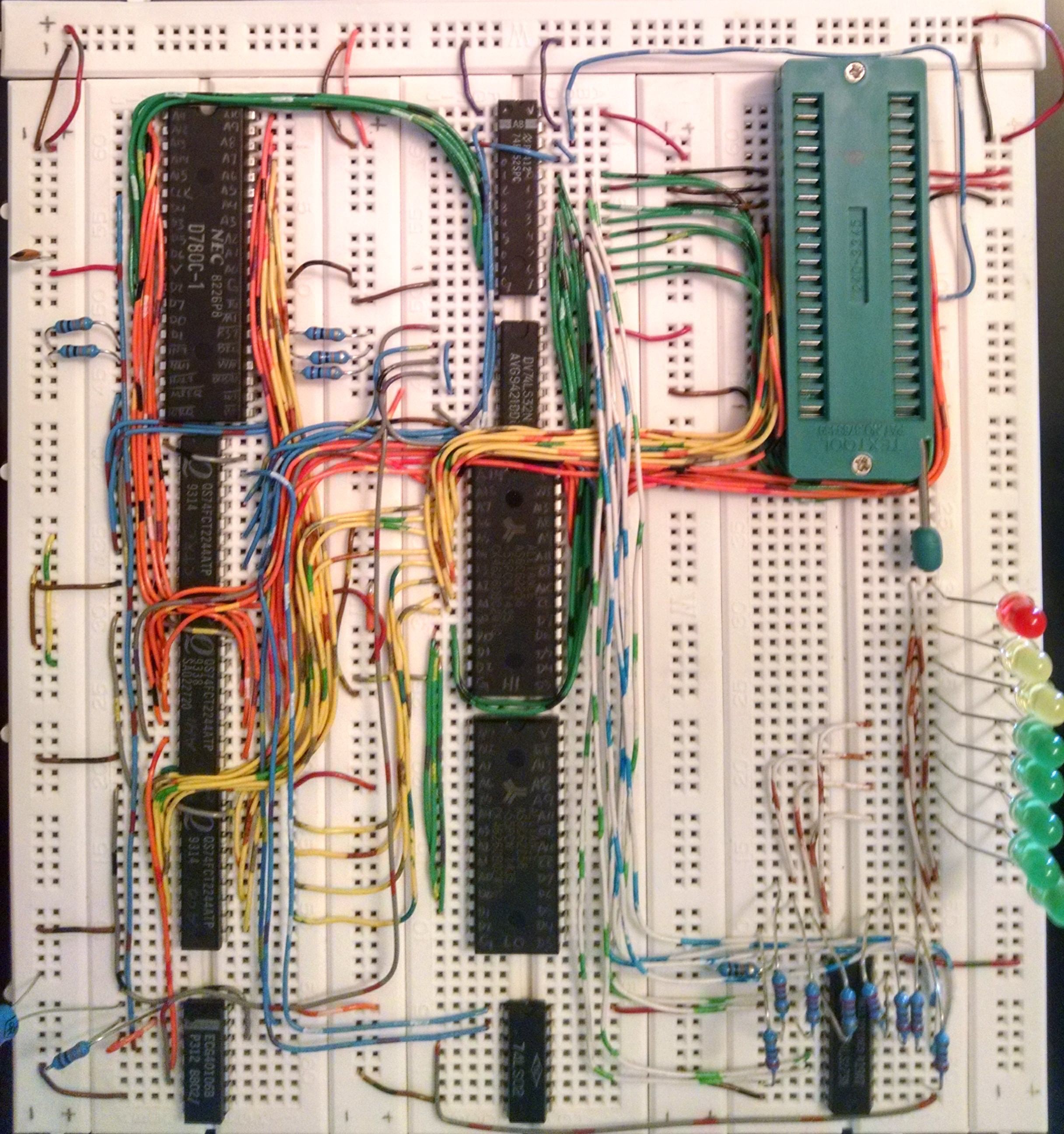
I've started building with the CPU board. It will have the Z80 itself; the oscillator and clock divider; logic for /MEMR, /IOR, etc; a flags register used for selecting memory banks, along with logic for selecting the register as IO device $FF; and the data/address bus buffers. It has been quite a task, taking over two weeks of soldering so far. I'm working from a logic/chip diagram I drew inspired by the infamous diagram of the original Macintosh.
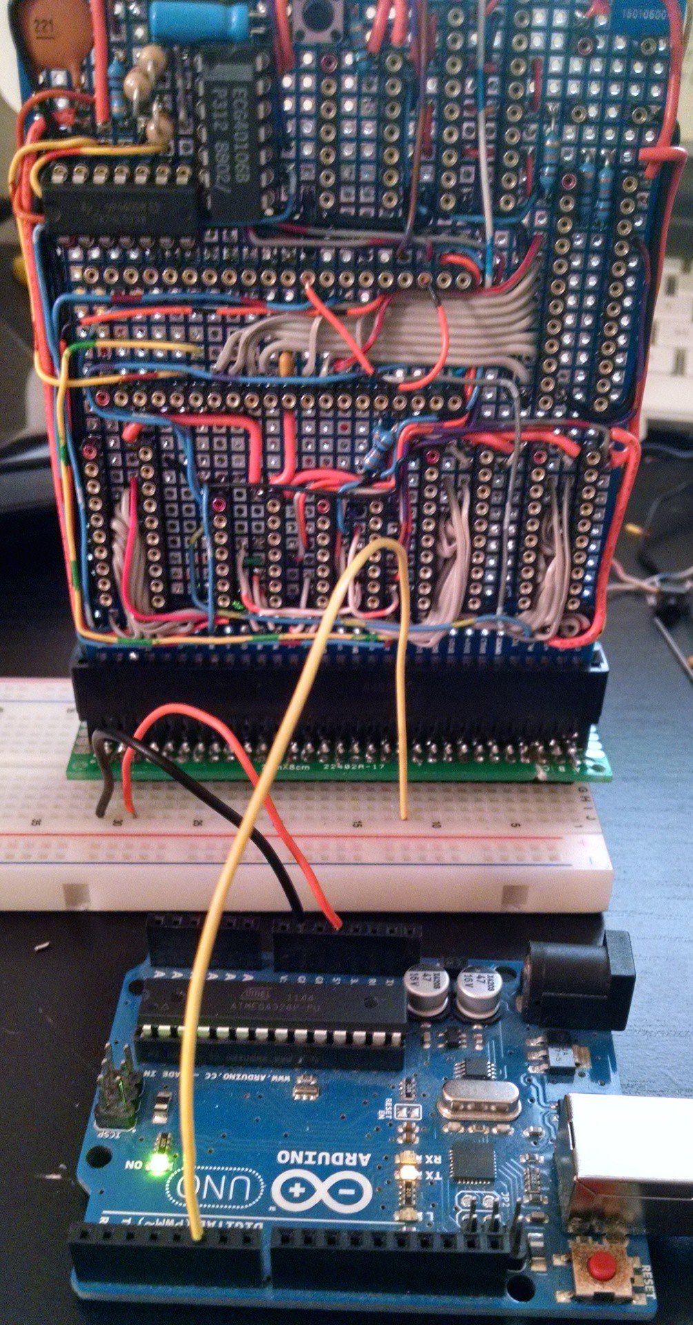
![Testing the clock]()
At this point I'm nearly finished with wiring the CPU card (with only the low byte of the address bus to the buffer unsoldered, because it will cover some other connections). I began testing with the clock generator, since everything else hinges on it working properly, and it gave me problems on the last design. I started with a basic Pierce Oscillator design, tested it by itself, and it seemed to be working. Next step was to add in the divider, for which I'm using a 74'93 counter. At this point, the oscillator was no longer working.
This is the problem I had with the clock last time. I have much to learn about designing and building a suitable oscillator. Since the Pierce design gave me so much trouble before, I switched to another design, with a list of several to try. An hour of desoldering (and delaminating) and resoldering, and I had my next oscillator ready to test.
This one seemed to be working great. A crude Arduino frequency counter showed the primary oscillator running around 4MHz and the divided rate right around 2MHz, and both fairly stable. A little faster than I expected from my 3.6864MHz crystal, but I figured that was just a measurement inaccuracy. Content with operation thus far, I began packing up for the night. This is when I realized that for my last tests, the crystal wasn't even in place. I used female machine headers for the crystal so I could swap it out if need be, and when I went to test, simply forgot to put it back in.
![The mysterious oscillator]()
Like I said, I have much to learn about oscillator design. I have no idea why I was able to get a fairly stable oscillator without the crystal, or why it was even remotely close to the frequency I was looking for. And even more confusing to me, I tested it with several crystals rated between 1MHz and 16MHz, and while I they would have an effect on the oscillation frequency, it was random and had nothing to do with the crystal frequency—the 16MHz crystal actually dropped it down to 1MHz!
All the same, so long as it's moderately stable, I'm ok with it. The divider should square it off to an acceptable 50% duty cycle, so it should work just fine for the Z80. For the accuracy the SCC demands, I'll just use the crystal directly connected to its own internal clock generator instead of running it off system clock. Still though, I wish I understood what was going on.
-
New Parts!
12/19/2015 at 04:01 • 0 commentsAfter the HAD article [Brandon Dunson] wrote about Tanner Electronics, and the subsequent realization that I'm only 30 miles away, I had to go check it out. Two hours and $35 later, this project has new life.
I picked up a 1.8432 MHz crystal and an oscillator of the same speed. It should be a good clock rate for the UART, and I think it would make a good rate for the main system clock as well. I also grabbed a couple 62-pin card edge sockets (ISA, anyone?) so I could experiment with mounting various sections of the computer on boards (à la [Quinn Dunki]), and I got a CompactFlash socket for booting CP/M (à la [Grant Searle] (whose web host blocked on all AT&T services)). For the sake of my future MC68000 project I got a couple 30-pin SIMM sockets (though if I can figure out the refresh, I might pull one into this project).
Most exciting of all though, Tanner's actually had the Z80 DMA. The DMA is the the hardest to find of the Z80 set. Mouser still carries the SIO, SCC, PIO, CTC, etc, but not the DMA. And since they had them, I did picked up a PIO and CTC. This means now I have a complete peripheral set for the Z80, and I'll be going back to almost to square one.
I'm thinking this time I'll do without the buffers. They worked, but I think they may have been the source of some of my problems when I tried running slightly more complex code. I do wish I had an oscilloscope to properly investigate it though. I'll probably keep my ROM/RAM setup the same, with a 32kB ROM swapping with the lower 32kB of RAM. I'll probably also stick with the '154 for IO address decoding, and the flags register for the ROM/RAM swap.
Now, planning is all well and good, but the project already got put on hold for one move, and another is coming up soon. So, I don't know when I'll actually get to sit and work on this again, but at least it's back on the front of my mind. As anxious as I am to sit down and draw it out, I should probably finish my weather display first, before it ends up permanently stuck in the limbo of the projects bin.
-
Serial I/O
06/22/2015 at 06:36 • 1 comment![]()
I never thought I'd be so happy to see a few characters slowly type out on screen. Serial communication has been the hardest part of this project so far. I'm using the Zilog Z8530 Serial Communication Controller (SCC). It's a versatile 2-channel programmable USART capable of speeds up to T1, and most notably used in the early Macintosh line for serial and LocalTalk.
With its versatility though, comes complexity. The SCC has sixteen registers for each channel (some shared though) that have to be programmed in the right order to properly configure the chip. Get the order wrong, and an internal race condition is likely. The manual warns of this possibility, but other than a few example assembly programs in the appendices, doesn't give much detail on what the proper order is. What finally worked for me was a combination of procedures found via Google, and old-fashioned trial-and-error.
...But configuring the chip was only one problem.
I have an old Mac Plus that didn't work when it was given to me fifteen years ago. I scavenged a few parts from it as a teenager, and it's been in storage since. I decided to pull the SCC from it, along with the MC68000 (next project). I don't have the best tools, but with time, a soldering iron, and a Radio Shack spring-loaded solder sucker, I was able to get most of the pins clear. Any pin that was tied to power or ground though, I couldn't get the solder to melt through. I'm assuming that the inner layers of the Plus motherboard are ground and power pours, and all that copper was just sucking up the heat. I finally got the chip free using a heat gun at work, but in the process got the chip far hotter than I felt was safe for it. Pretty sure I killed it there.
I tried it anyway - brought it home, wired it in, wrote and flashed a new program, aaaand ... nothing. Tried different combinations, different initialization orders, different clock speeds and baud rates ... nothing. Suspecting that I had killed the thing, I wired it in to my Arduino Mega, so I could try reading the registers to make sure they were even writing. Every register read back $00 every time. That settled it, I burned the chip trying to remove it.
Thankfully, Mouser still carries the Z85C30, and since they're practically in my back yard, by the next day I had a new one, along with a 3.6864 MHz crystal (the SCC's internal Baud Rate Generator can use the system clock, but a 3.6864 MHz clock will generate all common baud rates without jitter). So, replaced the old SCC with my new one in the Arduino test bed, and ... every register read back $00 every time. Nothing I did, no attempts at adjusting timing or sequence would read back anything other than 0 for any register.
Well, I seriously doubt the new chip is bad out of the box—surely it's just my Arduino sketch. So, I put the new SCC back in circuit with the Z80. Of course, nothing happened on the first try, but I changed a few parameters, re-burned my flash, and tried again ... and again ... and again ... and finally got gibberish.
At this point, garbage data was like gold. Garbage data means the chip is working. Garbage data means the SCC is properly configured for async, Tx is enabled, and it's accepting data. I pored over the settings, checking, rechecking every bit and its hexadecimal translation entered into my code. Still garbage. I changed the baud rate to something slower, surely 1200 should work fine. Still garbage. Finally I spot it—the careless mistake I had made, and confirmed, and checked over time after time ... baud rate source set to RTxCA instead of the Baud Rate Generator.
Sure, I had properly set up the BRG, I had set the BRG to use a crystal between RTxCA and SYNCA ... but then set channel A to use the raw clock on RTxCA, instead of the actual baud rate generated by the BRG from the RTxCA clock.
Did I mention the chip is a little complicated to set up properly?
After all this, finally I was able to reliably output a string of text every time the system was reset. After that though, nothing. My program was supposed to poll the SCC for data in the Rx buffer, and when data is available, read in and echo back. I'm certain the problem is my program, but this project is the first time I've ever used Assembly for anything more than just a few minor operations. Clearly I need more practice, but at this point, I just want the thing to work.
Enter Small Device C Compiler - SDCC. SDCC worked with no problems right out of the box. It does require you write your own getChar() and putChar() routines for stdio to work, but those were easy enough. So in no time at all, I had a new test program, in a language I could easily troubleshoot.
#include <stdio.h>

static __sfr __at 0x03 sccDatA;
static __sfr __at 0x02 sccDatB;
static __sfr __at 0x01 sccComA;
static __sfr __at 0x00 sccComB;
static __sfr __at 0xF0 flagsReg;

void boot() {
	__asm
		LD SP,#0xFF00
		CALL _main
	__endasm;
}

#define sccSetsCount 38
const unsigned char sccSets[] = {
	0x00,0x00,      //pointer reset
	0x09,0xC0,	//hardware reset
	0x04,0x04,	//1x clock, async, 1 stop, no par
	0x01,0x00,	//no dma, no interrupts
	0x02,0x00,	//clear int vector
	0x03,0xC0,	//rx 8 bits, disabled
	0x05,0x60,	//tx 8 bits, disabled
	0x09,0x01,	//status low, no interrupts
	0x0A,0x00,	//nrz encoding
	0x0B,0xD6,	//xtal, BRG for rxc, trxc output
	0x0C,0xfe,	//time constant low byte (1200)
	0x0D,0x05,	//time constant high byte(1200)
	0x0E,0x00,	//BRG source RTxC
	0x0E,0x80,	//clock source BRG
	0x0E,0x01,	//enable BRG
	0x0F,0x00,	//no ints
	0x10,0x10,	//reset interrupts
	0x03,0xC1,	//enable Rx
	0x05,0x68,	//enable Tx
	0x00,0x00	//overflow
};

void initSccA() {
	unsigned char i;
	for(i=0; i<sccSetsCount; i++){
		sccComA = sccSets[i];
	}
}

void main() {
	unsigned char c;
	flagsReg = 0x80;	//turn on LED
	initSccA();
	flagsReg = 0;		//turn off LED
	printf("SCC Init Complete");
	while(1){
		c = getchar();
		putchar(c);
	};
}

void putchar(char cin) {
	unsigned char c;
	//check status of tx buf, then output
	do{
		sccComA = 0;
		c = sccComA;
		c &= 4;
	}while(c == 0);
	sccDatA = cin;
}

char getchar() {
	unsigned char c;
	do{
		sccComA = 0;
		c = sccComA;
		c &= 1;
	}while(c != 1);
	c = sccDatA;
	return c;
}
By default, SDCC uses templates that make a lot of assumptions about the way the hardware is set up. In the case of the Z80, the template is built for a specific emulator. The quickest way to get my test program up and running was to disable the template, which once compiled will start executing with the first function listed. That's why I've inserted that boot() function at the beginning—it's the first thing executed, so it initializes the stack and calls main().The result of this compiles to a 3KB binary, thanks to the included stdio library. New problem. I've been copying lines from a hex file into the Arduino control monitor to program the flash rom. Not a problem with a program that's under 100 bytes. Very tedious for 3K of code. I now know enough Python to access a serial port, open a file, and output the file over the serial port. Success!
So, now I have a Z80 computer with 64kB of RAM, up to 32kB of ROM, 2-way serial communication via SCC, an easy way to program it, and an easy way to burn a new ROM ... and I don't know what to do with it. I keep looking over the source code for CP/M, but CP/M is a disk-based system. Without disks, 90% of the code is no longer relevant.
Maybe it's time to start on a new system with a Motorola 68000 while I think about it.
-
It's not the assembler
06/01/2015 at 05:14 • 0 commentsIt never fails. If you get to the point where you start to suspect the Assembler/Compiler/Automated-tool-built-by-someone-much-smarter-than-you is what isn't working, then humility is sure to follow.
I salvaged a Zilog 8530 SCC (UART) from an old motherboard, wired it in, and threw together a quick assembly program to initialise and test it. It didn't work. For debugging, and so I could know if my code was at least getting past the initialisation, I added an LED to a register I have tied to address $F0 on the IO bus (something I know worked before). It didn't work.
I have a '154 4-to-16 decoder I'm using for peripheral select. The Z80 OUT instruction will output an address on the low byte of the address bus. I'm using the high nybble (A4-A7) of this address to provide chip select lines for up to 16 peripherals, with the low nybble (A0-A3) available for the device (e.g. A/B select on the SCC).
Probing around the '154 to figure out why not even the LED would light, nothing was working as expected. Output 15 was never enabled, 0 only blipped, 3, blipped, and 1 was all over the place. It almost seemed like an endian mixup, but surely the assembler wouldn't mix up something like that.
No, of course it wasn't the assembler. I had wired the '154 to A0-A3, instead of A4-A7. It didn't show up before, because I had always used $FF or $00 as the output address. Now that I'm to the point of using $F0 for the register, and $00-$03 for the SCC, it's a significant problem.
In my defense, thanks to allergy medication, I'm surprised I know which way is up. Cursed Spring.
-
First Run
05/09/2015 at 22:28 • 2 comments![]()
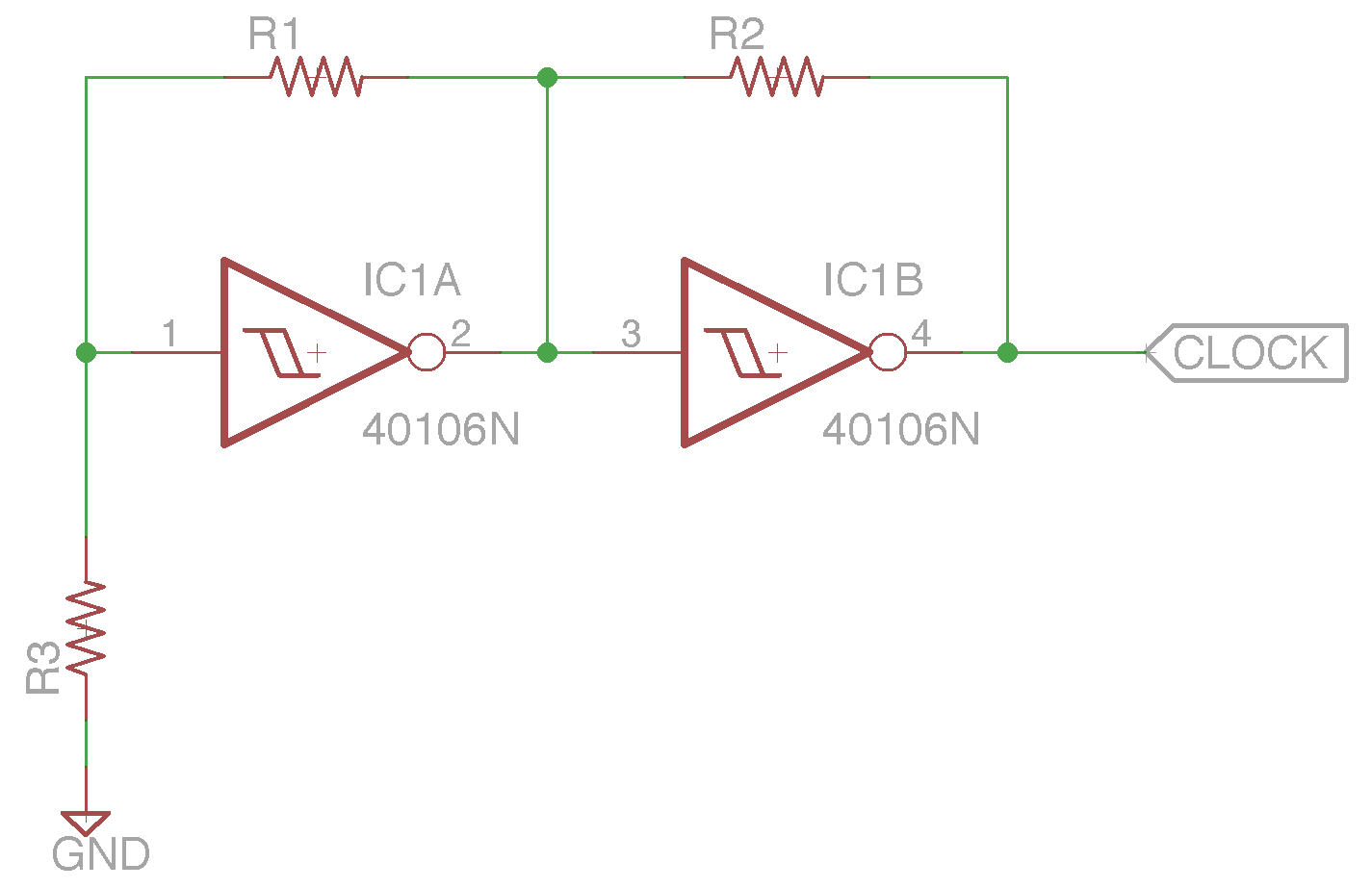
I spent a few hours last night wiring up my breadboard. I'm using three 74x244 buffers for the address bus and control signals, a '652 transceiver for the data bus, a '32 quad OR for some glue logic, and a '273 register for output. My Flash is serving as ROM on the low addresses, and an SRAM on the high addresses. The second RAM chip is on the board, but not wired in yet. Eventually I plan on being able to bank swap ROM for RAM in the low addresses. Clock is provided by an oscillator built from a 40106b hex Schmitt trigger inverter.
My first test program is a simple as could be. 0x01 is loaded in to register A, then a loop of output A, rotate A.
ASM and Hex compiled by zasm:
            org    0
            LD     A,1H
myLoop:     OUT    0h,A
            RLC    A
            JP     myLoop
:090000003E01D300CB07C302004E :00000001FF
The clock of the '273 is tied to the OR of /IOREQ and /WR, so it latches on every OUT instruction. The result is LEDs 0-7 lighting up one-by-one then starting over with LED 0.I can't believe it actually works ...
-
Flash Programmer - Finishing Up
05/07/2015 at 23:50 • 2 commentsI've finally completed the code for programming my flash ROMs, and successfully tested all functions for the first time. The code is an absolute mess, but I'm posting it here in case anyone else might find it useful. I've broken out the functions specific to working with the flash into a library. This is my first experiment with classes in C++, so forgive me if its implementation is non-standard.
The Arduino sketch posted below will present a prompt and menu for working with the chip. The Read function will read the specified address range and output Intel Hex format. The Write function parses Hex format and programs the chip with it. Extended Linear Address entries are used to select the sectors on the chip (0-7, for 8 64k sectors). Verify checks the lock bits for the specified sector, and scans through the sector looking for any bytes that are programmed (not reading $FF).
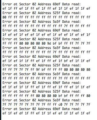
I did run into a few problems while testing the programmer. The first was I noticed that between reads of the same area on the flash chip I was testing with, the value returned was inconsistent. Sometimes it would be just a single bit different on one read out of three ($FF $7F $FF), but sometimes it would be three very different reads ($7F $1F $60). My first thought was perhaps I needed decoupling capacitors, so I broke out the soldering iron. No change. Maybe I'm not accounting for setup time, so I added a delay, and read the byte three times in a row before bringing OE back up. No change. Finally, I threw together a quick sketch that would scan through the entire address range of the ROM and read each byte sixteen times, and report any that were inconsistent.
![]()
Clearly, this chip has a bad sector. I pulled these chips out of a wall-mount touch panel that is at least 15 years old, so a bad sector is not surprising. Of the four, two have bad sectors.
The other big problem I ran into while testing was none of the flash chips wanted to respond to any of the write commands. I pored over the datasheet for hours, checking, rechecking the commands, the timing diagrams, everything I could think of. Nothing seemed out of place, and I know I had it working before I moved from the breadboard. ... Which of course means that must be where it went bad. Sure enough, another quick sketch to step through the address pins one-by-one, and I had swapped A14 and A15 when building the board. Trying to desolder from the cheap import board resulted in completely removing the copper pad as well, but I got them connected the right way in the end. It was pretty exciting to see the byte write command complete successfully, and be able to read back in the data I had written.
Programmer library and Arduino sketch below:
AM29_Flash.h
/* AM29F040 Flash memory library
 * This library was designed for the 512KB AMD AM29F040 chip
 * to be programmed with an Arduino Mega.
 *
 * Modification will be required to work with anything else
 * I make no guarantees this code will work for you, and provide
 * it here as an example of what worked for me.
 *
 * To use, first edit this header to fill in the proper ports
 * for the high and low address bytes, and the DQ byte.
 * I used Port A for address low, Port C for address high,
 * and Port K for DQ. The constructor for AM29 will set which
 * Arduino pins are used for A16-A18, and for the control signals.
 * Calling the setup() method will set all pins as input/output
 * as necessary, disable pullups, and set initial values.
 */
#include <stdint.h>

#ifndef __JA__AM29__FLASH__INCLUDED__
#define __JA__AM29__FLASH__INCLUDED__

#define AM29ADDRLOPORT     PORTA
#define AM29ADDRLODDR    DDRA
#define AM29ADDRHIPORT     PORTC
#define AM29ADDRHIDDR    DDRC
#define AM29IOPORT    PORTK
#define AM29IODDR    DDRK
#define AM29IOPIN    PINK

#define NOP() do { __asm__ __volatile__ ("nop"); } while(0);

#define cSECTORLIMIT 7

class AM29{
private:
    int A16;
    int A17;
    int A18;
    int CE;
    int OE;
    int WE;

public:
    AM29(int,int,int,int,int,int);

    void setup();

    void setAddr(uint32_t addr);
    void setAddr(uint8_t sector, uint16_t addr);

    uint8_t readByte(uint32_t addr);
    uint8_t readByte(uint8_t sector, uint16_t addr);

    int verifySector(uint8_t sector);

    int progressCheck(uint8_t data, uint32_t addr);

    void byteWrite(uint8_t data, uint32_t addr);

    int programByte(uint8_t data, uint8_t sector, uint16_t addr);
    int programByte(uint8_t data, uint32_t addr);

    void autoSelect();
    void readReset();

    int eraseSector(uint8_t sector);

    int eraseChip();
};

#endif
AM29_Flash.cpp
#include "pins_arduino.h"
#include "wiring_private.h"
#include <avr/pgmspace.h>
#include <stdint.h>
#include "AM29_Flash.h"

AM29::AM29 (int inA16, int inA17, int inA18, int inCE, int inOE, int inWE){
    A16 = inA16;
    A17 = inA17;
    A18 = inA18;
    CE = inCE;
    OE = inOE;
    WE = inWE;
}

void AM29::setup(){
    //call to set up proper port directions and initialize
    AM29ADDRLODDR = 0xFF;    //lo addr output
    AM29ADDRLOPORT = 0;
    AM29ADDRHIDDR = 0xFF;    //hi addr output
    AM29ADDRHIPORT = 0;

    //Sector addr outputs
    pinMode(A16, OUTPUT);
    digitalWrite(A16, LOW);
    pinMode(A17, OUTPUT);
    digitalWrite(A17, LOW);
    pinMode(A18, OUTPUT);
    digitalWrite(A18, LOW);

    AM29IODDR = 0;        //io input
    AM29IOPORT = 0;        //io disable pullup

    //Control signal outputs (Active low)
    pinMode(CE, OUTPUT);
    digitalWrite(CE,HIGH);
    pinMode(OE, OUTPUT);
    digitalWrite(OE,HIGH);
    pinMode(WE, OUTPUT);
    digitalWrite(WE,HIGH);
}

//set the address pins to the given address
void AM29::setAddr(uint32_t addr){
    setAddr( (uint8_t)(addr>>16), (uint16_t)addr);
}
void AM29::setAddr(uint8_t sector, uint16_t addr){
    AM29ADDRLOPORT = (uint8_t)addr;
    AM29ADDRHIPORT = (uint8_t)(addr>>8);
    digitalWrite(A16, (sector & (1<<0)));
    digitalWrite(A17, (sector & (1<<1)));
    digitalWrite(A18, (sector & (1<<2)));
}


//read in uint8_t at given address
uint8_t AM29::readByte(uint32_t addr){
    return(readByte( (uint8_t)(addr>>16), (uint16_t)addr));
}
uint8_t AM29::readByte(uint8_t sector, uint16_t addr){
    boolean errorFound = false;
    digitalWrite(CE, LOW);
    setAddr(sector, addr);
    digitalWrite(OE, LOW);
    NOP();
    NOP();
    uint8_t b = AM29IOPIN;
    digitalWrite(OE, HIGH);
    digitalWrite(CE, HIGH);
    setAddr(0);

    return(b);
}

int AM29::verifySector(uint8_t sector){
    //return 0 for sector erased
    //return -1 for error
    //return 1 for sector programmed
    //return 2 for sector erased but locked
    //return 3 for sector programmed and locked
    int retval = 0;
    bool lock = false;
    if(sector > cSECTORLIMIT) return(-1);

    uint32_t startA = sector;
    startA = startA << 16;
    uint32_t endA = startA;
    endA |= 0xFFFF;

    //check sector lock
    autoSelect();
    uint8_t b = readByte(startA + 2);
    readReset();
    if(b&1) lock = true;

    //check sector data
    do{
        if(readByte(endA) != 0xFF){
            retval = 1;
            break;
        }
        endA--;
    }while(endA > startA);

    if(lock) return(retval+2);
    else return(retval);
}

int AM29::progressCheck(uint8_t data, uint32_t addr){
    //returns -1 for error
    //returns 0 for operation in progress
    //returns 1 for valid
    //this function based on flow chart in datasheet

    uint8_t b, c;
    b = readByte(addr);
    c = readByte(addr);

    if((b&(1<<6)) != (c&(1<<6))){
        //toggle bit has toggled
        if((c&(1<<5)) == (1<<5)){
            //possible error
            b=readByte(addr);
            if((b&(1<<6)) == (c&(1<<6))){
                //toggling has stopped
                if(b == data) return(1);
                else return(-1);
          }else{
            return(-1);
          }
        }else{
            return(0);
        }
    }else{
        if(b == data) return(1);
        else return(-1);
    }
}

//output given byte at given address
void AM29::byteWrite(uint8_t data, uint32_t addr){
    digitalWrite(CE, LOW);
    digitalWrite(OE, HIGH);
    setAddr(addr);
    AM29IODDR = 0xFF;
    AM29IOPORT = data;
    digitalWrite(WE, LOW);
    delayMicroseconds(60);
    digitalWrite(WE, HIGH);
    delayMicroseconds(60);
    digitalWrite(CE, HIGH);
    AM29IOPORT = 0;
    AM29IODDR = 0;
}

//program uint8_t at given address, including setup commands
//returns -2 if programmed, -1 if verification error, 1 if ok
int AM29::programByte(uint8_t data, uint8_t sector, uint16_t addr){
    uint32_t fullAddr = (sector << 16);
    fullAddr += addr;
    return(programByte(data, fullAddr));
}
int AM29::programByte(uint8_t data, uint32_t addr){
    if(readByte(addr) != 0xFF) return(-2);

    autoSelect();
    byteWrite(0xAA, 0x05555);
    byteWrite(0x55, 0x02AAA);
    byteWrite(0xA0, 0x05555);
    byteWrite(data, addr);
    readReset();

    //verify
    int check=0;
    do{
        check = progressCheck(data, addr);
        Serial.print(".");
    }while(check==0);
    return(check);
}

//Send the autoSelect command
void AM29::autoSelect(){
    byteWrite(0xAA, 0x05555);
    byteWrite(0x55, 0x02AAA);
    byteWrite(0x90, 0x05555);
    uint8_t b = readByte(0);
}

//Send the readReset command
void AM29::readReset(){
    byteWrite(0xF0, 0);
}

//Erase the given sector
int AM29::eraseSector(uint8_t sector){
    uint32_t addr = sector;
    addr = addr << 16;
    Serial.println(String(addr,HEX));
    byteWrite(0xAA, 0x05555);
    byteWrite(0x55, 0x02AAA);
    byteWrite(0x80, 0x05555);
    byteWrite(0xAA, 0x05555);
    byteWrite(0x55, 0x02AAA);
    byteWrite(0x30, addr);
    delayMicroseconds(80);
    int check = 0;
    do{
        check = progressCheck(0xFF, addr);
        Serial.print(".");
    }while(check==0);
    return(check);
}

//Erase entire chip
int AM29::eraseChip(){
    byteWrite(0xAA, 0x05555);
    byteWrite(0x55, 0x02AAA);
    byteWrite(0x80, 0x05555);
    byteWrite(0xAA, 0x05555);
    byteWrite(0x55, 0x02AAA);
    byteWrite(0x10, 0x05555);

    int check = 0;
    do{
        check = progressCheck(0xFF, 0);
        Serial.print(".");
    }while(check==0);
    return(check);
}
And the Arduino sketch with a serial menu using the above functions:
#include <AM29_Flash.h>

#define A16 38
#define A17 39
#define A18 40
#define CE 56
#define OE 57
#define WE 58

AM29 flash = AM29(A16, A17, A18, CE, OE, WE);

void setup() {
  //setup code
  flash.setup();

  Serial.begin(115200);
  Serial.println(F("\nFlash Memory Manager"));
  Serial.println(F("(C)2015 techav"));
  Serial.println();
}

void loop() {
  mainMenu();
}

void printHex8(uint8_t in){
  Serial.print(String((in>>4) & 0x0F,HEX));
  Serial.print(String((in & 0x0F),HEX));
}
void printHex16(uint16_t in){
  Serial.print(String((in>>12) & 0x000F, HEX));
  Serial.print(String((in>>8) & 0x000F, HEX));
  Serial.print(String((in>>4) & 0x000F, HEX));
  Serial.print(String((in & 0x000F), HEX));
}

void writeFlashMenu() {
  boolean exit = false;
  uint8_t sector = 0;
  uint16_t addr = 0;
  uint8_t writeCount;

  do{
    String input;
    Serial.print(F("?"));
    input = readLineConsole();

    uint8_t inBuf[255];
    int e = input.length()-1;
    int bufLoc = 0;
    uint8_t checksum = 0;
    uint8_t readSum = 0;
    for(int i=1; i<e; i+=2){
      uint8_t b = strtoul(input.substring(i,i+2).c_str(),NULL,16);
      inBuf[bufLoc++] = b;
    }
    bufLoc--;
    for(int i=0; i<bufLoc; i++){
      checksum += (uint8_t)inBuf[i];
    }
    checksum = (~checksum)+1;
    bufLoc++;

    readSum = (uint8_t)strtoul(input.substring(e-1).c_str(),NULL,16);
    if(checksum != readSum){
      Serial.println(F("Invalid checksum!"));
      return;
    }
    switch(inBuf[3]){
      case(0):
        //data
        writeCount = 0;
        addr = inBuf[1];
        addr = addr << 8;
        addr += inBuf[2];
        Serial.print(F("Starting at address "));
        printHex16(addr);
        Serial.println();
        do{
          int r = flash.programByte(inBuf[writeCount+4],sector,addr);
          switch(r){
            case(1):
              Serial.println();
              break;
            case(-2):
              Serial.println(F("Sector is programmed. Erase and try again. Exiting."));
              return;
              break;
            case(-1):
            default:
              Serial.print(F("Unkown error programming uint8_t "));
              printHex8(inBuf[writeCount+4]);
              Serial.print(F(" to address "));
              printHex16(addr);
              Serial.println();
              break;
          }
          addr++;
          writeCount++;
        }while(writeCount<inBuf[0]);
        break;
      case(1):
        //end of file
        Serial.println(F("End of file reached. Exiting."));
        exit=true;
        break;
      case(4):
        //sector
        sector = inBuf[5];
        Serial.print(F("Jumping to sector "));
        printHex8(sector);
        Serial.println();
        break;
      default:
        Serial.print(F("Record type "));
        printHex8(inBuf[3]);
        Serial.println(F(" not supported at this time."));
    }
  }while(!exit);
}

void verifyFlashMenu() {
  String input;
  uint8_t sector = 0;
  bool valid = false;
  do{
    Serial.print(F("Select Sector to verify (1-8): "));
    input = readLineConsole();
    sector = (uint8_t)input.toInt();
    if(sector > 0 && sector < 9){
      valid = true;
      sector--;
    }
  }while(!valid);
  int r = flash.verifySector(sector);
  switch(r){
    case(3):
      Serial.println(F("Sector is Locked"));
    case(1):
      Serial.println(F("Sector has data"));
      break;
    case(2):
      Serial.println(F("Sector is Locked"));
    case(0):
      Serial.println(F("Sector is erased"));
      break;
    default:
      Serial.println(F("An unknown error occurred"));
  }
}

void eraseFlashMenu() {
  String input;
  uint8_t sector=0;
  bool valid = false;
  Serial.print(F("Erase CHIP or SECTOR? "));
  input = readLineConsole();
  if(input == F("CHIP")){
      //Chip erase
      Serial.print(F("Type YES to confirm chip erase: "));
      input = readLineConsole();
      if(input == F("YES")){
        int r = flash.eraseChip();
        if(r==1){
          Serial.println(F("Chip erase successful"));
        }else{
          Serial.println(F("An error occurred. Please verify Flash contents"));
        }
      }else{
        Serial.println(F("Operation cancelled."));
      }
  }else if(input == F("SECTOR")){
    //Sector erase
    do{
      Serial.print(F("Select Sector to erase (1-8): "));
      input = readLineConsole();
      sector = (uint8_t)input.toInt();
      if(sector > 0 && sector < 9){
        valid = true;
        sector--;
      }
    }while(!valid);
    Serial.print(F("Type YES to confirm erase sector "));
    Serial.print(sector + 1);
    Serial.print(F(": "));
    input = readLineConsole();
    if(input == F("YES")){
      int r = flash.eraseSector(sector);
      if(r==1){
        Serial.println(F("Chip erase successful"));
      }else{
        Serial.println(F("An error occurred. Please verify Flash contents"));
      }
    }
  }else{
    Serial.println(F("Invalid selection. Aborting"));
  }
}

void readFlashMenu() {
  String input;
  uint8_t sector;
  uint32_t addr, count;
  bool valid = false;
  do{
    Serial.print(F("Select Sector (1-8): "));
    input = readLineConsole();
    sector = (uint8_t)input.toInt();
    if(sector > 0 && sector < 9){
      valid = true;
      sector--;
    }
  }while(!valid);
  //Serial.println(sector);
  valid = false;
  do{
    Serial.print(F("Start address for read ($0000-$FFFF): $"));
    input = readLineConsole();

    addr = strtol(input.c_str(),NULL,16);
    if(addr >= 0 && addr < 0xFFFF) valid = true;
  }while(!valid);
  //Serial.println(String(addr,HEX));
  valid = false;
  do{
    Serial.print(F("End address for read ($0000-$FFFF): $"));
    input = readLineConsole();
    count = strtol(input.c_str(),NULL,16);
    if(count > addr && count <= 0xFFFF) valid = true;
  }while(!valid);
  //Serial.println(String(count,HEX));

  //start with printing Extended Address record
  Serial.print(F(":0200000400"));
  printHex8(sector);
  printHex8((~(6+sector))+1);
  Serial.println();
  //read and output Flash data
  do {
    int a;
    uint8_t checksum = 0;
    if((count-addr)>=16){
      a = 16;
    }else{
      a = count-addr+1;
    }

    Serial.print(":");
    printHex8(a);      //uint8_t count
    printHex16(addr);  //start address
    printHex8(0);      //field type

    checksum += a;
    checksum += (uint8_t)(addr>>8);
    checksum += (uint8_t)(addr);

    for(a; a>0; a--){
      uint8_t b = flash.readByte(sector, addr);
      checksum += (uint8_t)b;
      printHex8(b);
      addr++;
    }
    checksum = (~checksum)+1;
    printHex8(checksum);
    Serial.println();
  }while(addr < count);
  Serial.println(F(":00000001FF"));
}

String readLineConsole() {
  String rx;
  bool lineTerm = false;

  do{
    if(Serial.available()){
      char c = Serial.read();
      if(c >= 'a' && c <= 'z'){
        c -= 0x20;
      }
      if(c == 0x0A){
        lineTerm = true;
      }else if(c != 0x0D){
        rx += c;
      }
    }
  }while(!lineTerm);
  //flush out anything else that may be in the buffer
  //after the line termination
  while(Serial.available()){
    char c = Serial.read();
  }
  Serial.println(rx);
  return(rx);
}

void mainMenu() {
  Serial.print(F("> "));
  String rx = readLineConsole();
  if(rx == F("READ")){
    readFlashMenu();
  } else if(rx == F("WRITE")){
    //
    writeFlashMenu();
  } else if(rx == F("VERIFY")){
    verifyFlashMenu();
  } else if(rx == F("ERASE")){
    eraseFlashMenu();
  } else {
    //show help
    Serial.println(F("Command List:"));
    Serial.println(F("Help - (This List)"));
    Serial.println(F("Read - Read data from Flash"));
    Serial.println(F("Write - Write data to Flash"));
    Serial.println(F("Erase - Erase data from Flash"));
    Serial.println(F("Verify - Check Flash sector status"));
  }
}
In hindsight, I suppose I could have made this a project all its own, but here it is, as part of my Z80 project.
-
Flash Programmer
05/03/2015 at 07:32 • 0 commentsI've been working through the code for reading/writing/erasing my flash chips. I've got reading down and outputting hex format nicely. Chip erase is working, but sector erase still needs some work. For writing, I've been working on the code separately, and have it correctly parsing hex format; I just need to roll it in to the rest of my code. I'm getting to the point where the code is unmanageable in the Arduino environment though. I need to get a programmer and start using a real IDE.
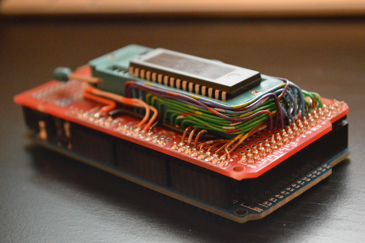
I spent the last two weeks obsessively checking the USPS tracking site hoping for any update on the parts I ordered from China to come in, and finally today they were delivered. I got some 40-pin ZIF sockets, pin headers, a Mega shield protoboard, and after a few hours soldering, I have an Arduino Mega Flash Programmer Shield. Not my prettiest soldering job, but it works. I am a little annoyed with myself for a careless wiring mistake—my control lines I ran around the board to Analog 2-4, when I meant to run them to Digital 2-4, which would have been a short, straight shot. Oh well, it works either way.
Hopefully once this semester has wrapped up I'll be able to finish the programmer and get some code burned, so I can start testing the Z80. I think I've got my initial schematic figured out, but need to order more buffer/drivers and maybe a few other odds and ends logic. I want to try to build the glue logic out of 7400-series, but if budget doesn't allow, I'll use the Altera CPLD I already have.
I also picked up a used copy of "Microcomputers and Microprocessors" at Half Price Books. It goes through interfacing and programming the Z80, 8080, and 8085. It has already proved very helpful for a few points I was fuzzy on.
![]()
-
Memory
04/12/2015 at 20:17 • 0 commentsWith its 16-bit address bus, the Z80 can access up to 64KB of memory. It has built-in support for DRAM refresh, using the low byte of the address bus to provide a refresh address during the second half of the M1 cycle. I don't have any RAM on hand that would work with something so old as a Z80, so I'll have to order some. DRAM refresh sounds like a hassle (especially using such a slow clock starting out), and isn't currently available in through-hole packages or 5-Volt, so I'm going with the obvious choice of SRAM. To try and minimize chip count, I'm going to use a pair of 32KB SRAMs with A15 selecting between the two.
As for ROM, I have an old Crestron touch panel built primarily with socketed ICs, including four 512KB AMD AM29F040 Flash memory chips. My plan is to use the lowest 32K of one of them and bank switch with the low RAM. This will put my ROM at address $0000 on boot, so I don't have to try to feed a 3-byte jump instruction on reset. I've seen a number of different ways to pull off the switch, but what makes the most sense to me is to put a register on the IO Bus that handles the swap.
What I'm thinking is a pair of 4-to-16 decoders on the address bus, enabled by IORQ (which I'll need for peripherals anyway). A high address like $FF will select an 8-bit register. Bit 7 on the register will select between ROM (clear) and RAM (set). On reset, register is cleared, and Z80 starts executing from $0000, which is ROM. ROM copies what it needs into the high RAM (CP/M sits at the top anyway), then jumps up to a routine that will set the bit for bank swap. With this approach, I could use the additional bits of the register to swap out additional pages of the ROM, by connecting them to the address lines above A14.
Before I can do any of this though, I need to figure out how to program the Flash, and I want to back up what is currently on the chips, just in case. My first thought was an Arduino Uno with a couple of shift registers outputting the addresses, and PORTD as data bus with the Flash. I'm sure I could have made it work, but after my first attempt failed, I remembered I had picked up an Arduino Mega from one of the closing Radio Shack stores. I used ports A and C for the first 16 address lines, and since those are numbered as digital pins 22-37, I just used 38-40 as A16-A18 (though I would really like to know whose idea it was to number the pins on the Mega in such a haphazard way, with some ports counting up, some counting down, and some just mixed at random). PORTK was data, and PORTE serial and control signals. I can read the entire memory and output it as ASCII-encoded Hex over serial at 115200Kbps in no time at all.
Now I just need to make sense of the datasheet and figure out how to erase and write to the Flash.
![]()
-
Beginnings
04/12/2015 at 05:27 • 0 commentsFor years, I have wanted to try building an 8-bit computer from bare chips—ever since as a young teenager I saw a build log where someone was building a computer around a 68HC11. I stared at those schematics for hours unable to decipher much beyond which thick line was the data bus. The idea was planted though.
I've learned much since then, but there is still much, much more that I don't know. I think I'm finally at the point where I know enough to at least get started.
Over the years as the idea has jumped in and out of my head, I've debated different processors—6502, 6811, 8080, Z80 ... even 16-bit chips like 8086—but the one that has always stood out is the Z80. When I was a kid, my family had an old Sanyo MBC-1000 which ran CP/M on a Z80. That old machine with its green phosphor display is etched into my memory.
In March of this year (2015), my uncle gave me his old electronics kit and a bucket of miscellaneous components and wires. Sorting through this I found a Z80, a Z80A, and a D780C-1 Z80 clone. Suddenly I had no excuse to not give it a try.
I'm working with the D780C-1, because it was in the best shape. To start out, I've built an oscillator out of a 40106b, running at about 10Hz. I've got it free-running with data pins all pulled low (NOP). It may not be much, but there is a certain feeling of accomplishment seeing the address lines count up.
It's hard to find a 7-segment decoder with hex support, and all the ones I have on-hand are BCD only. So, I'm currently driving the displays with an Arduino and a couple of '164 shift registers. Messy, but it works for now. I've ordered a Terasic USB Blaster, and I have an Altera MAX 7000 CPLD from a digital logic class. Plan is to drive a 4-digit multiplexed display with it so I can see the entire address bus.