-
Shorter Legs--New Walk Attempt
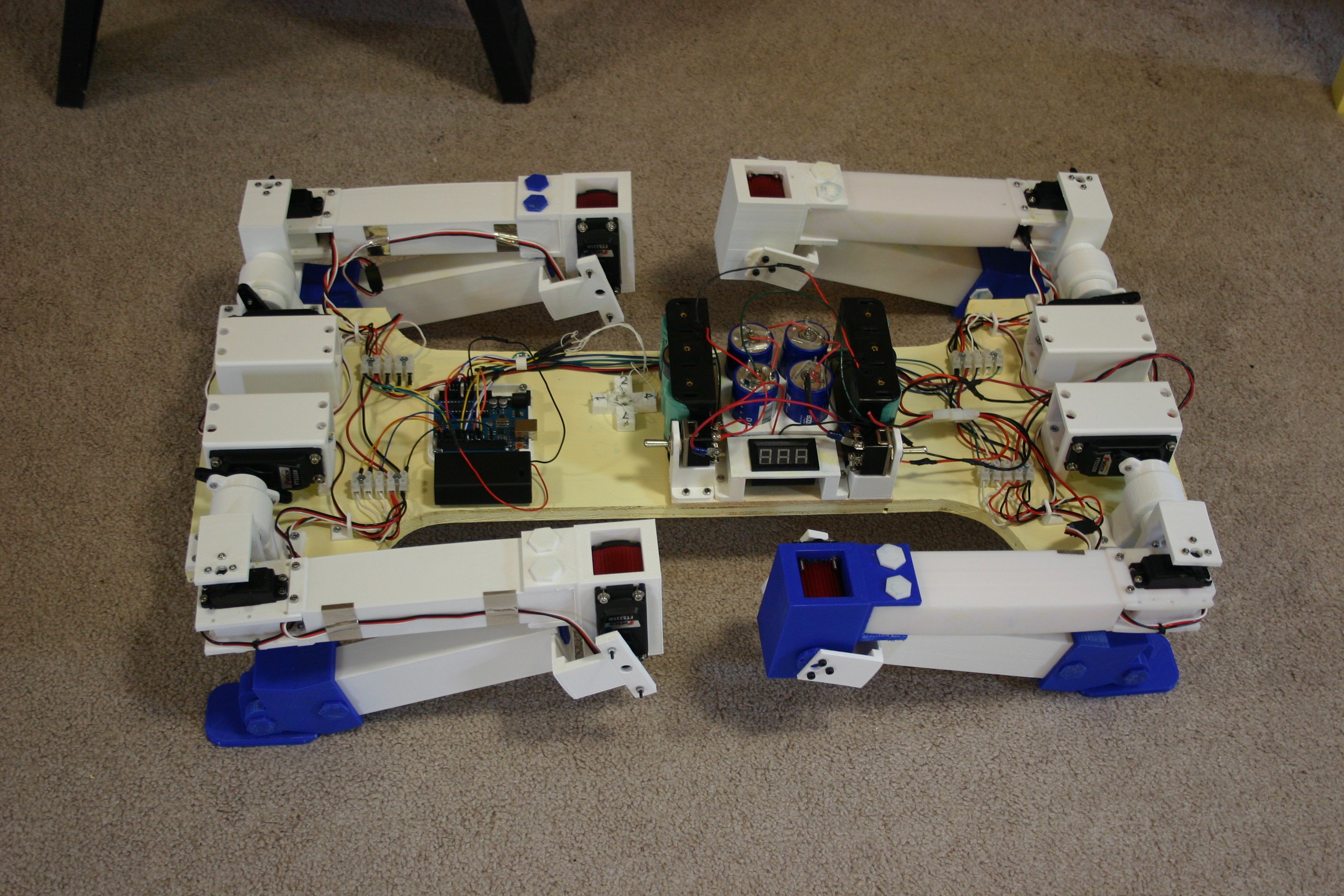
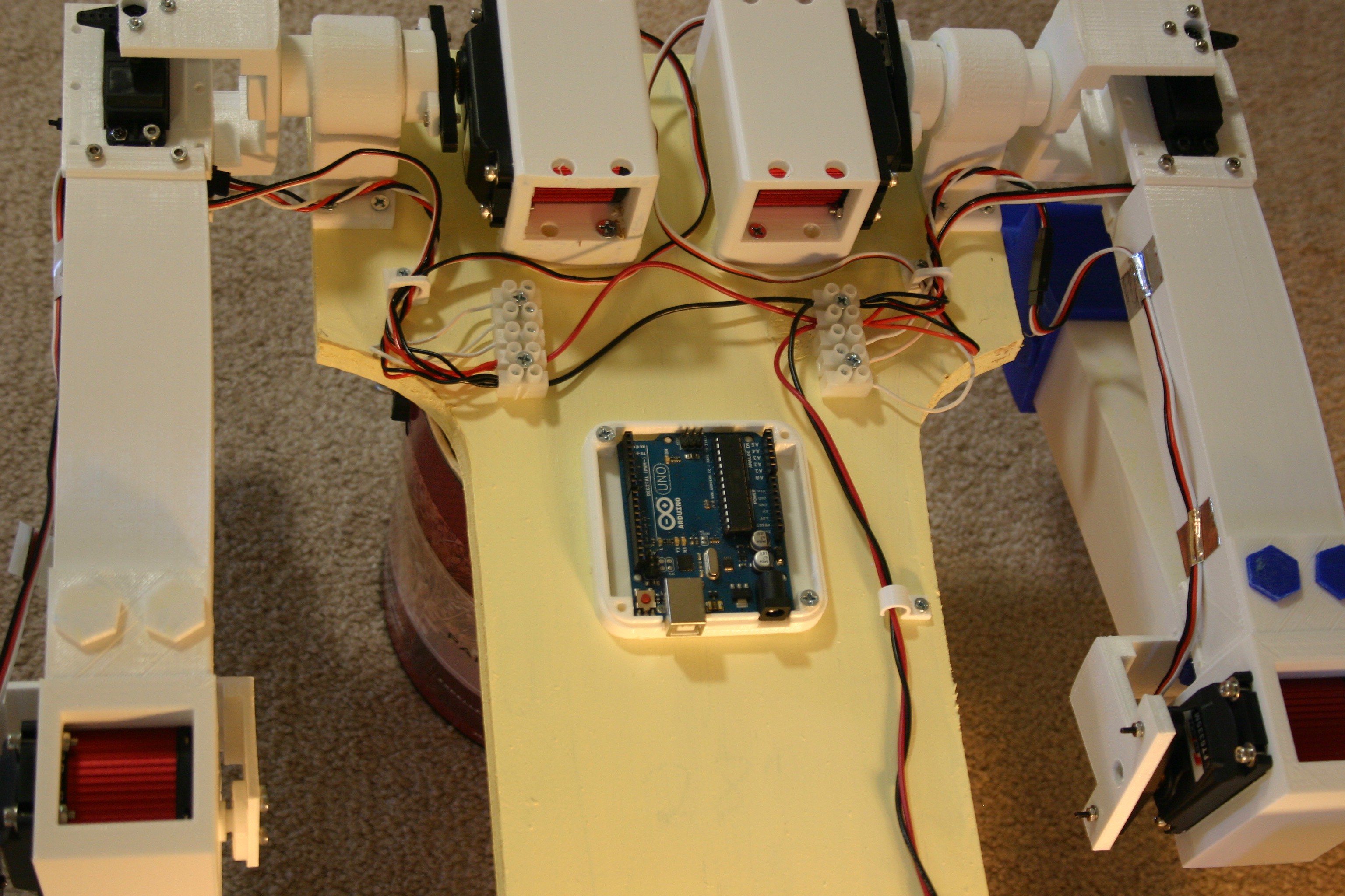
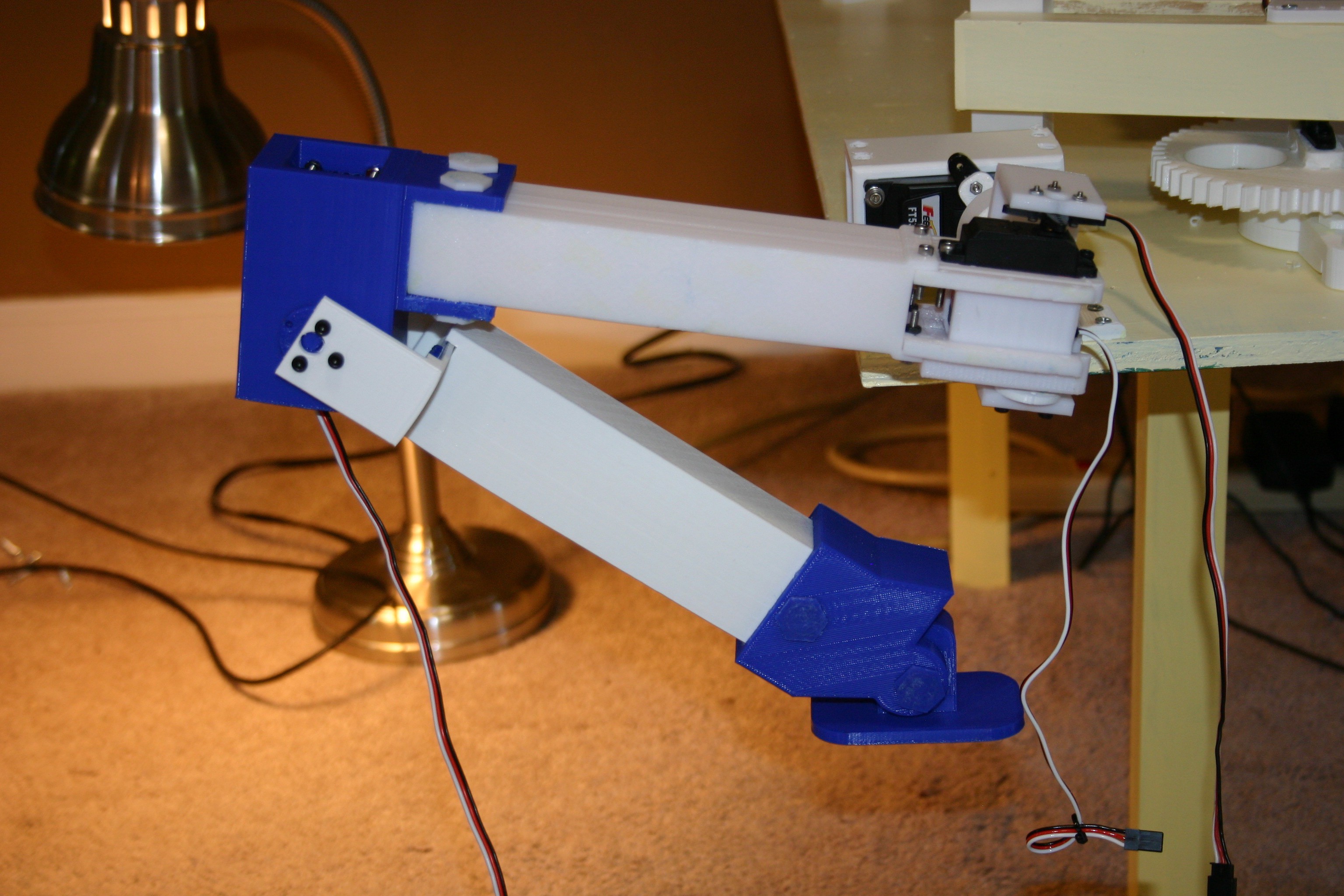
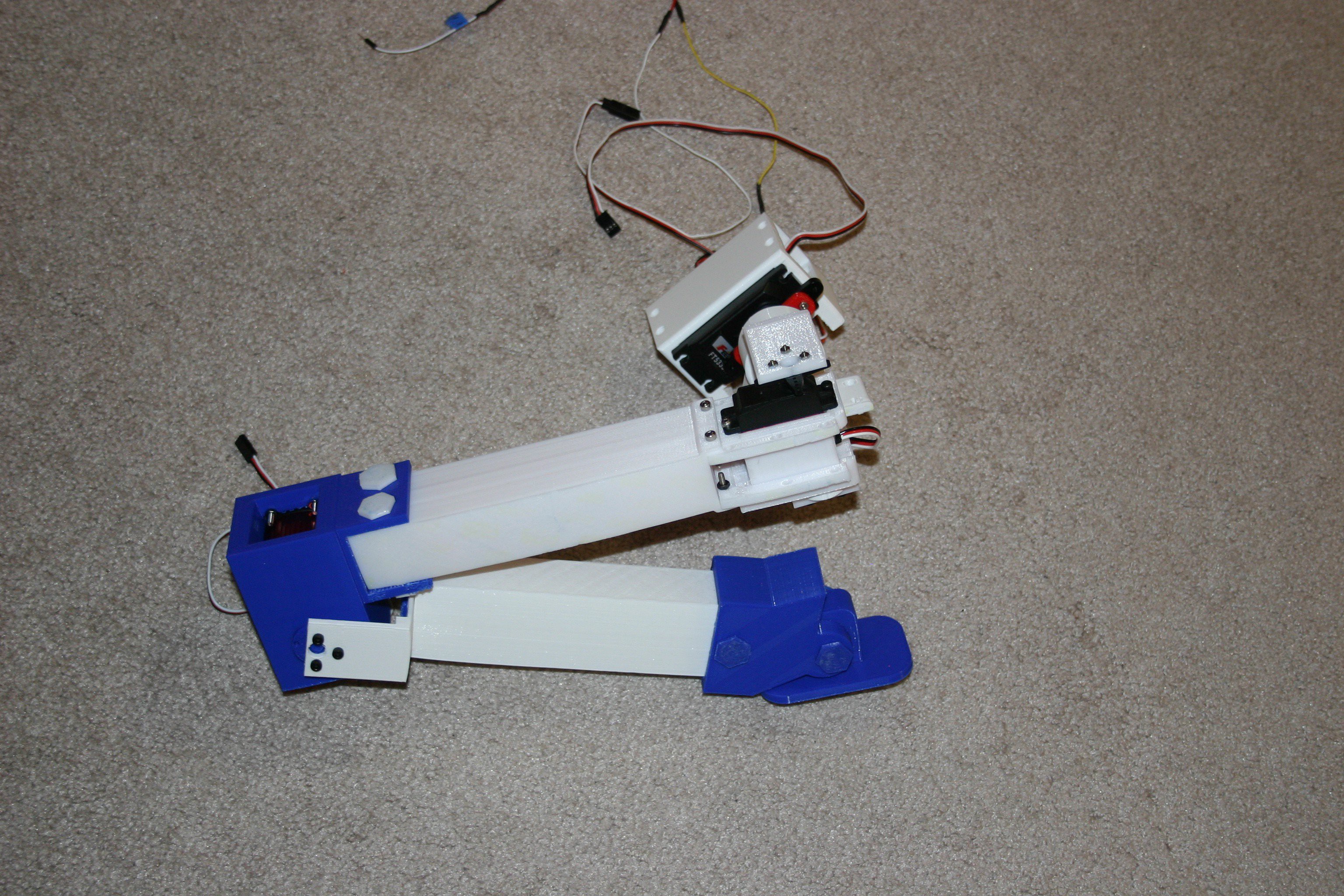
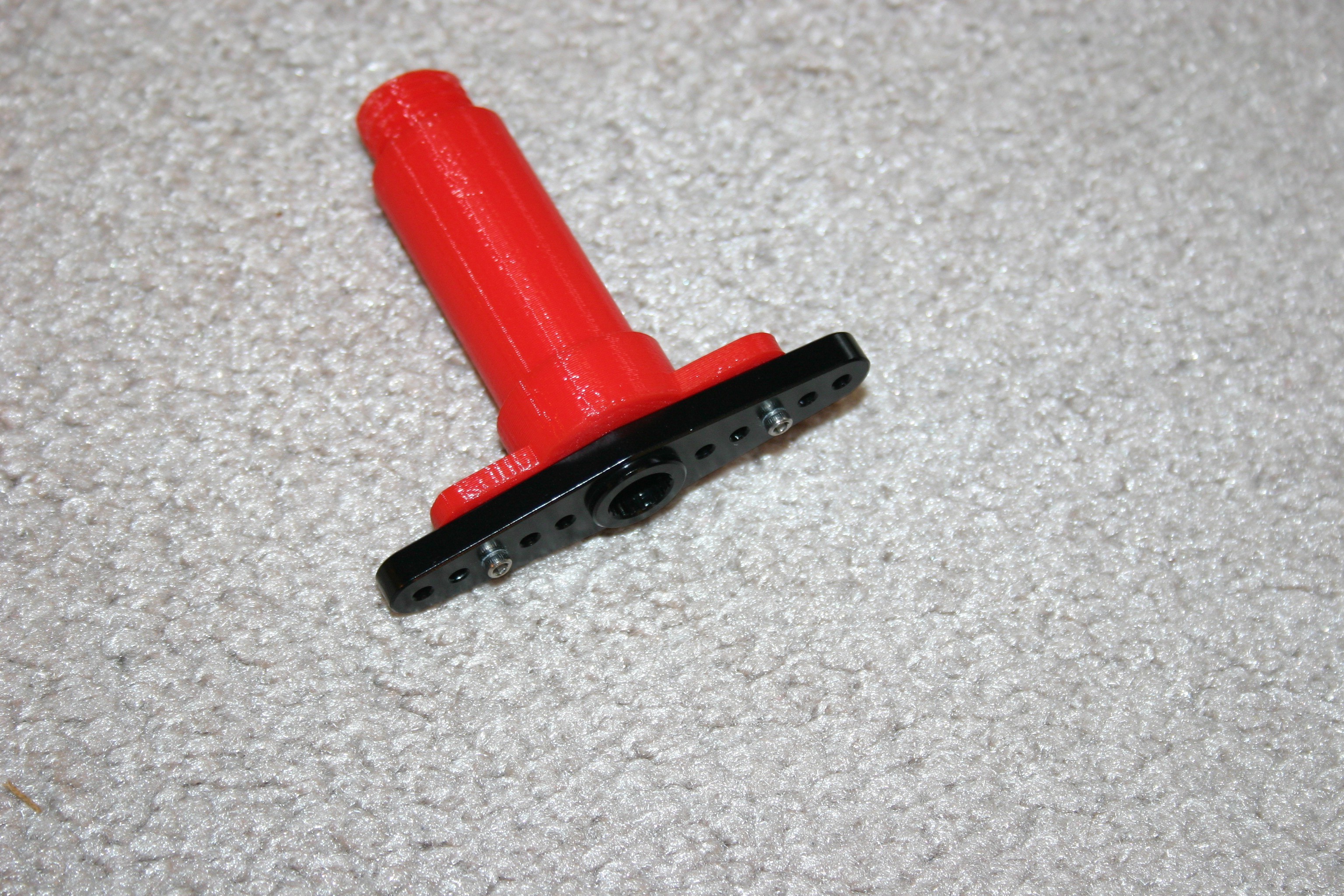
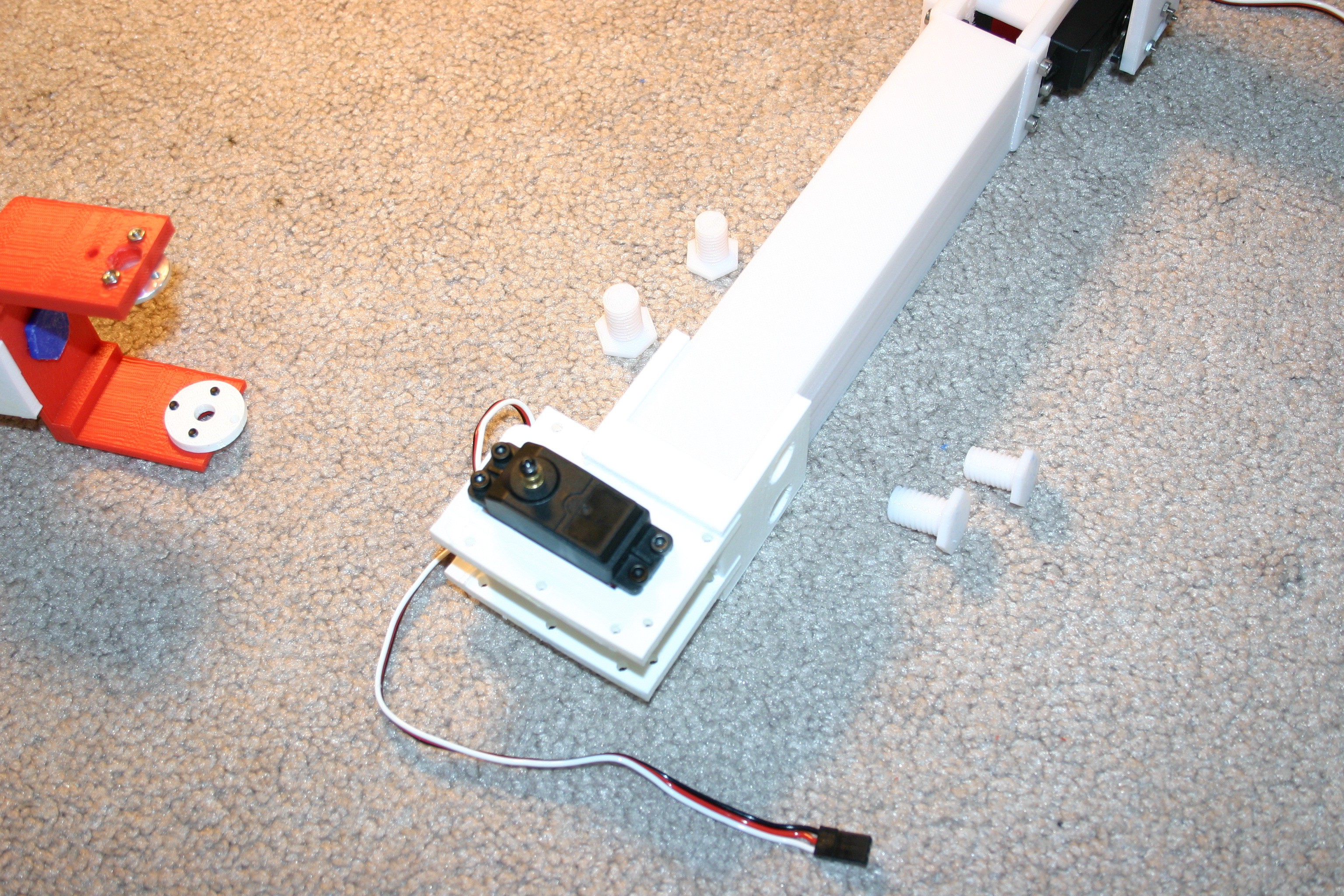
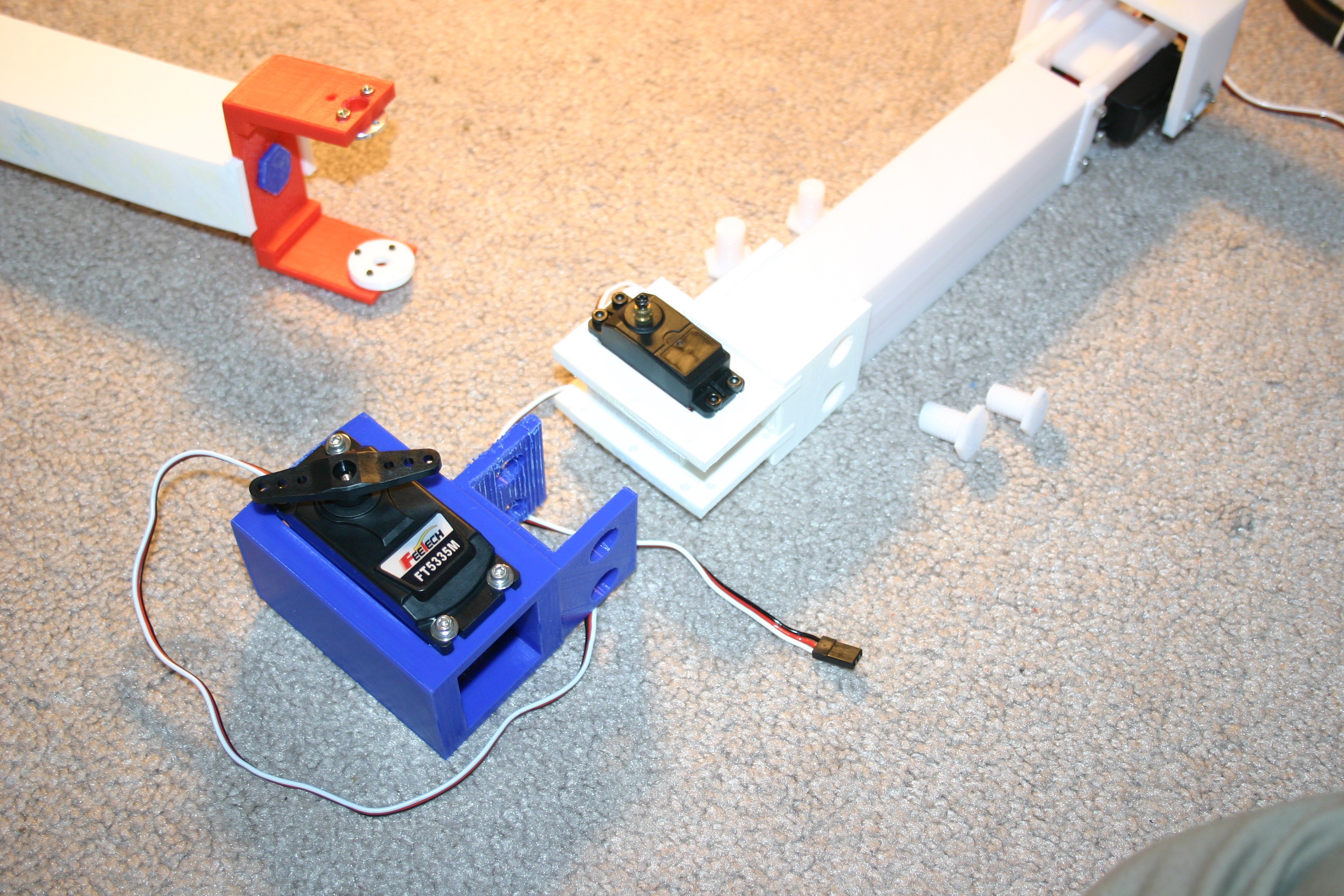
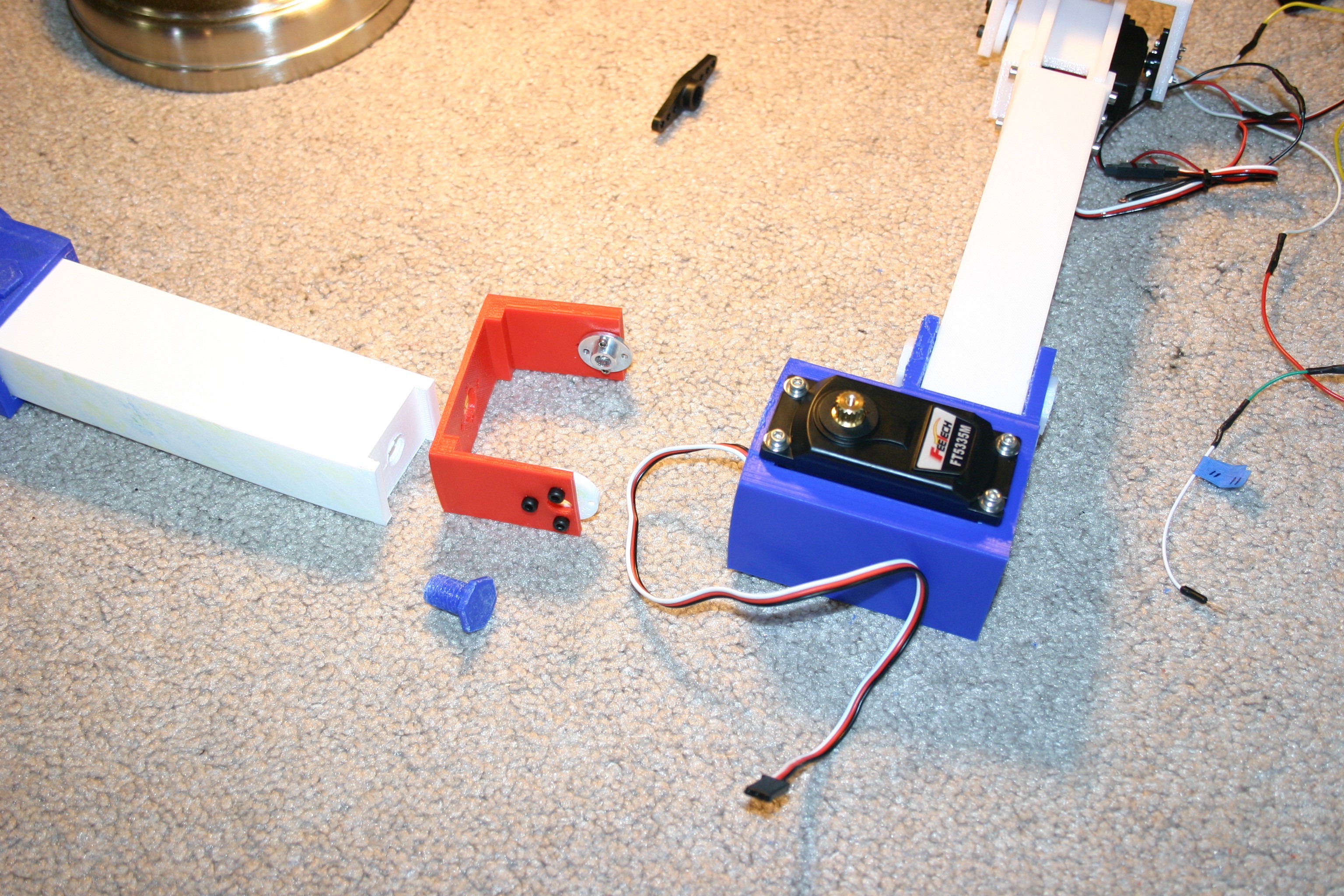
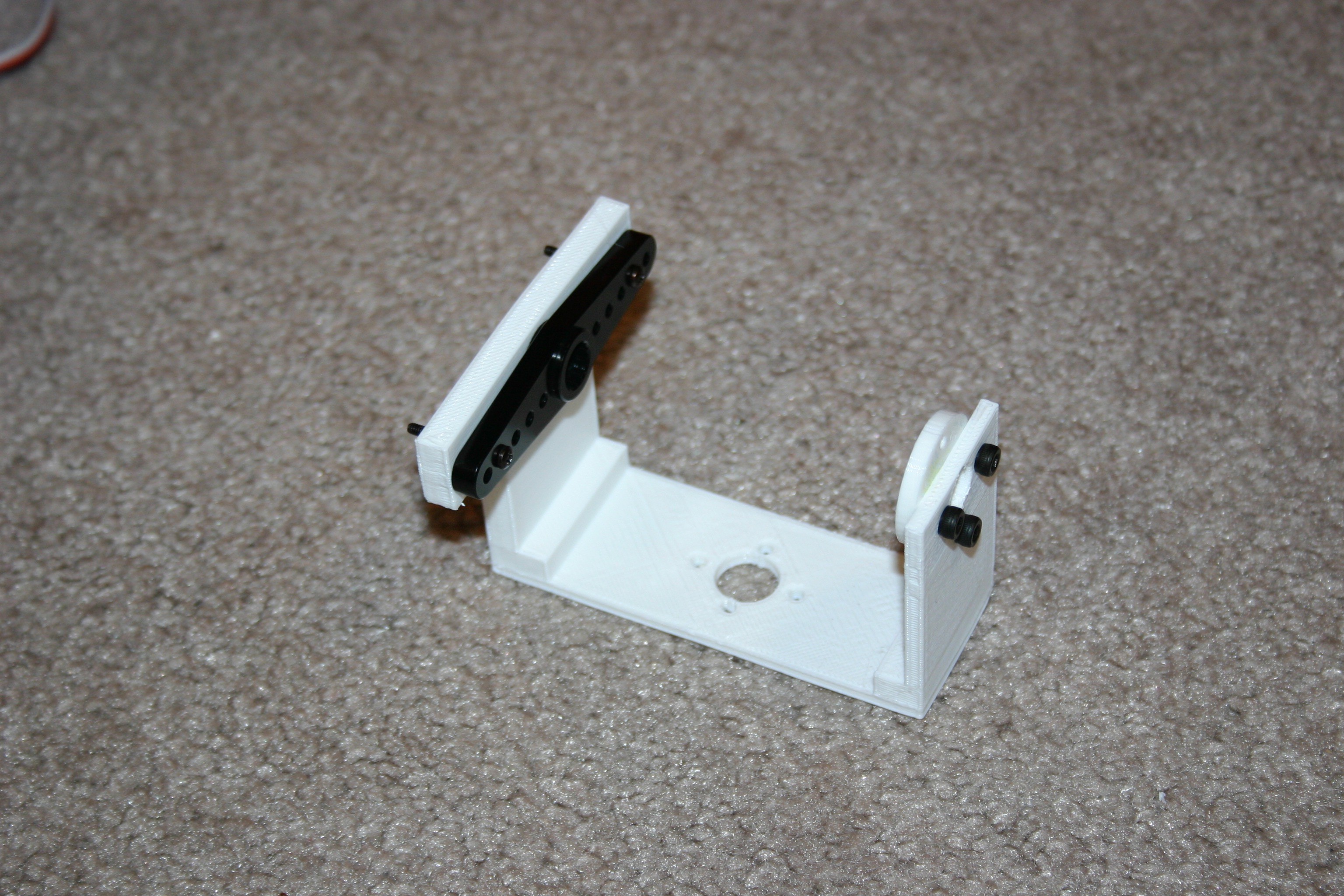
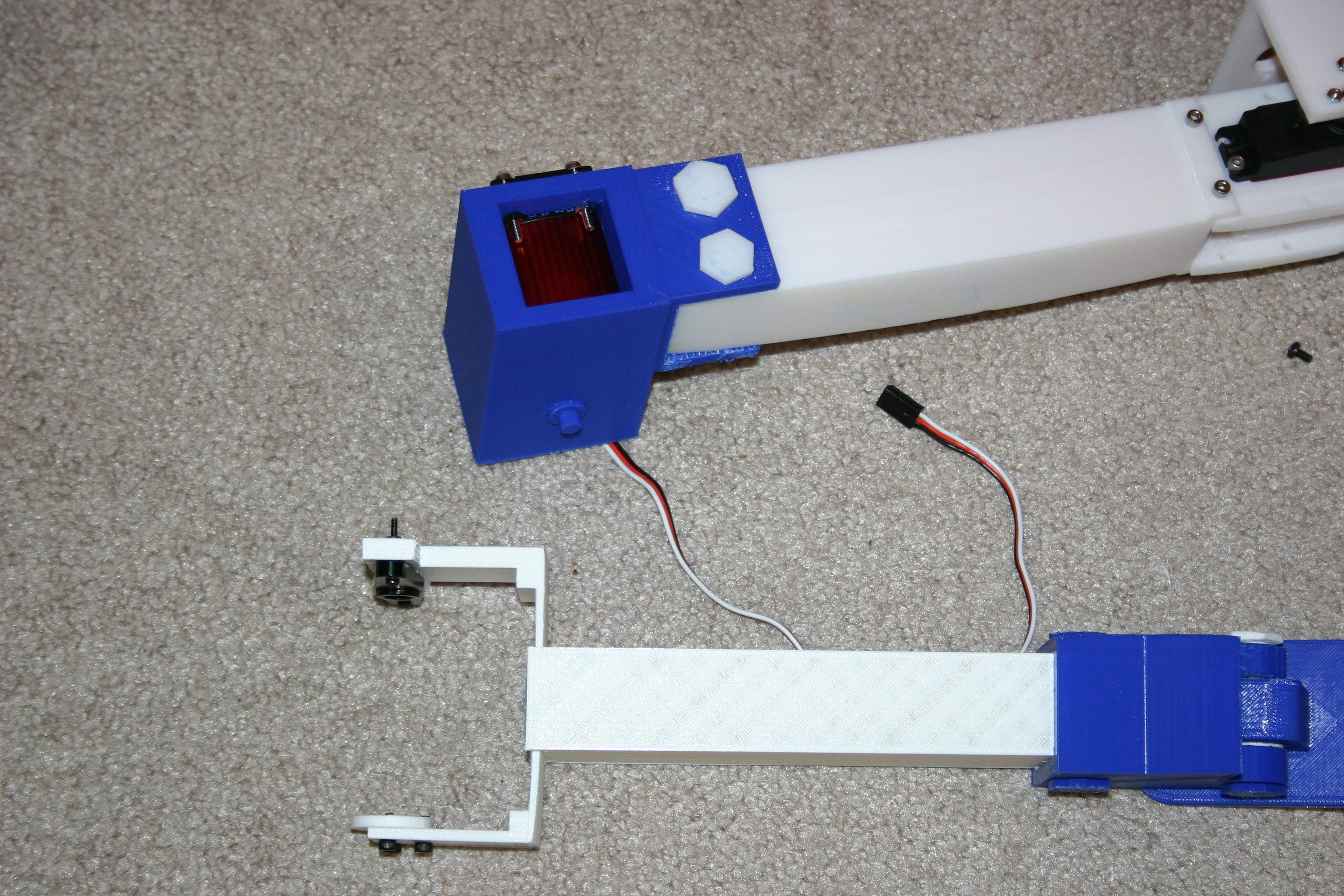
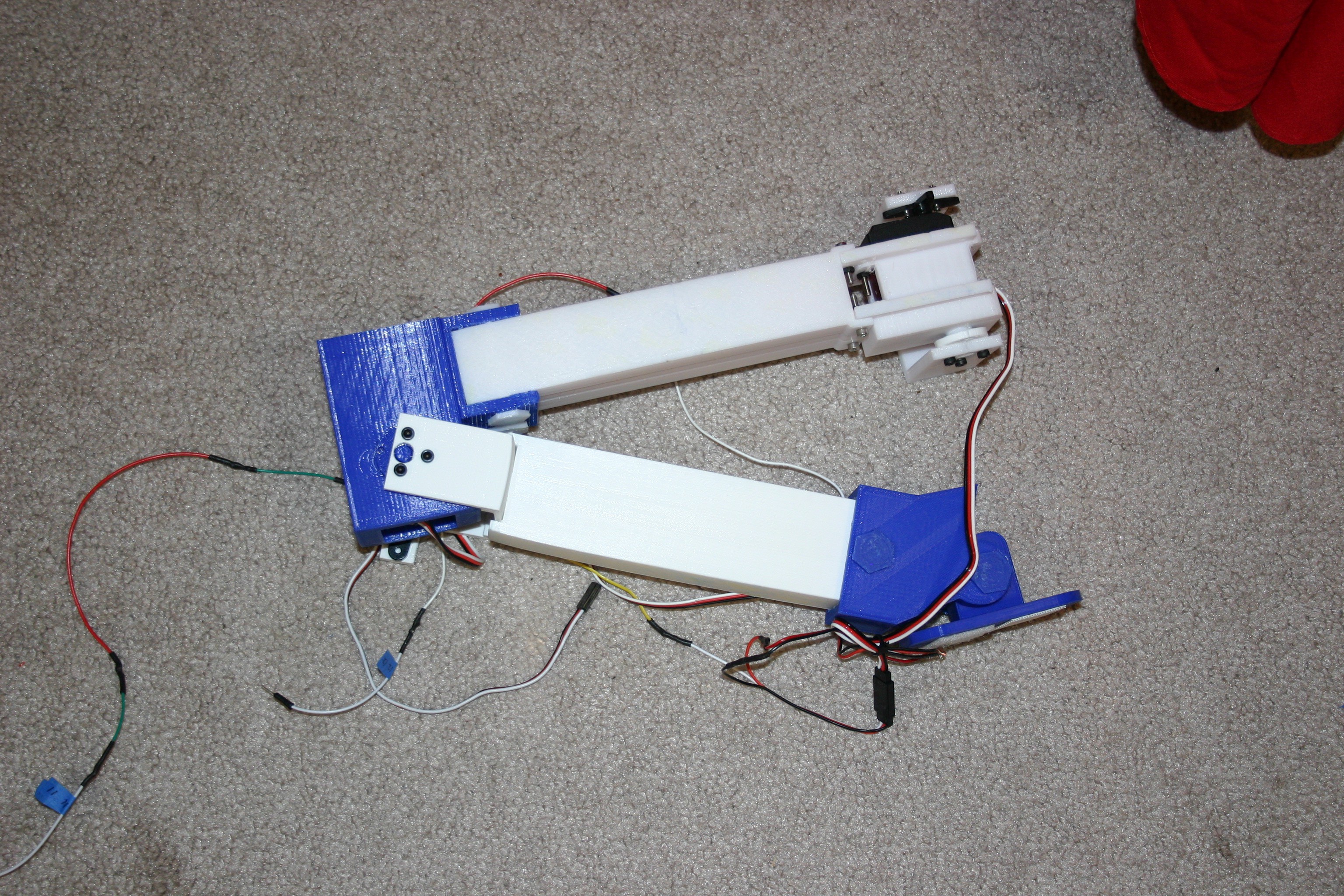
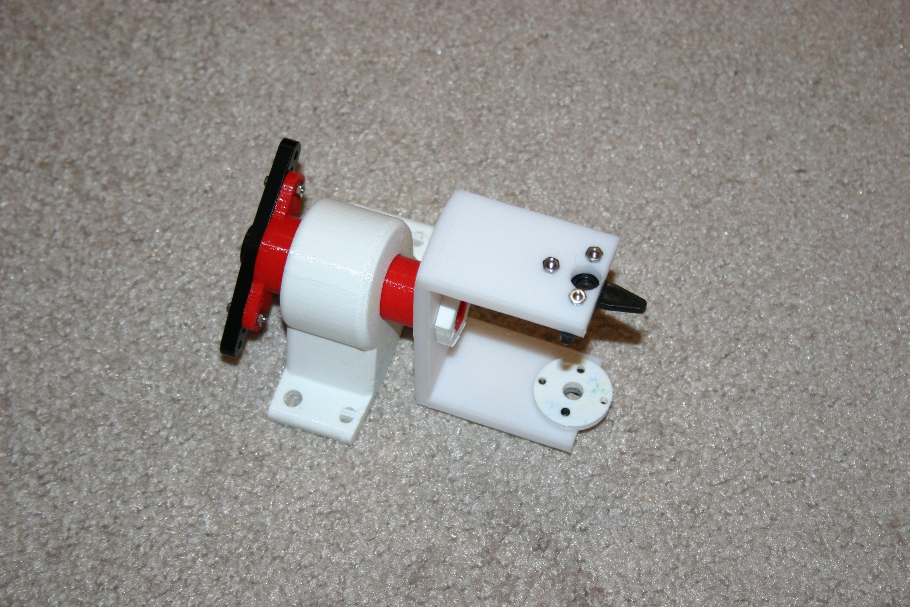
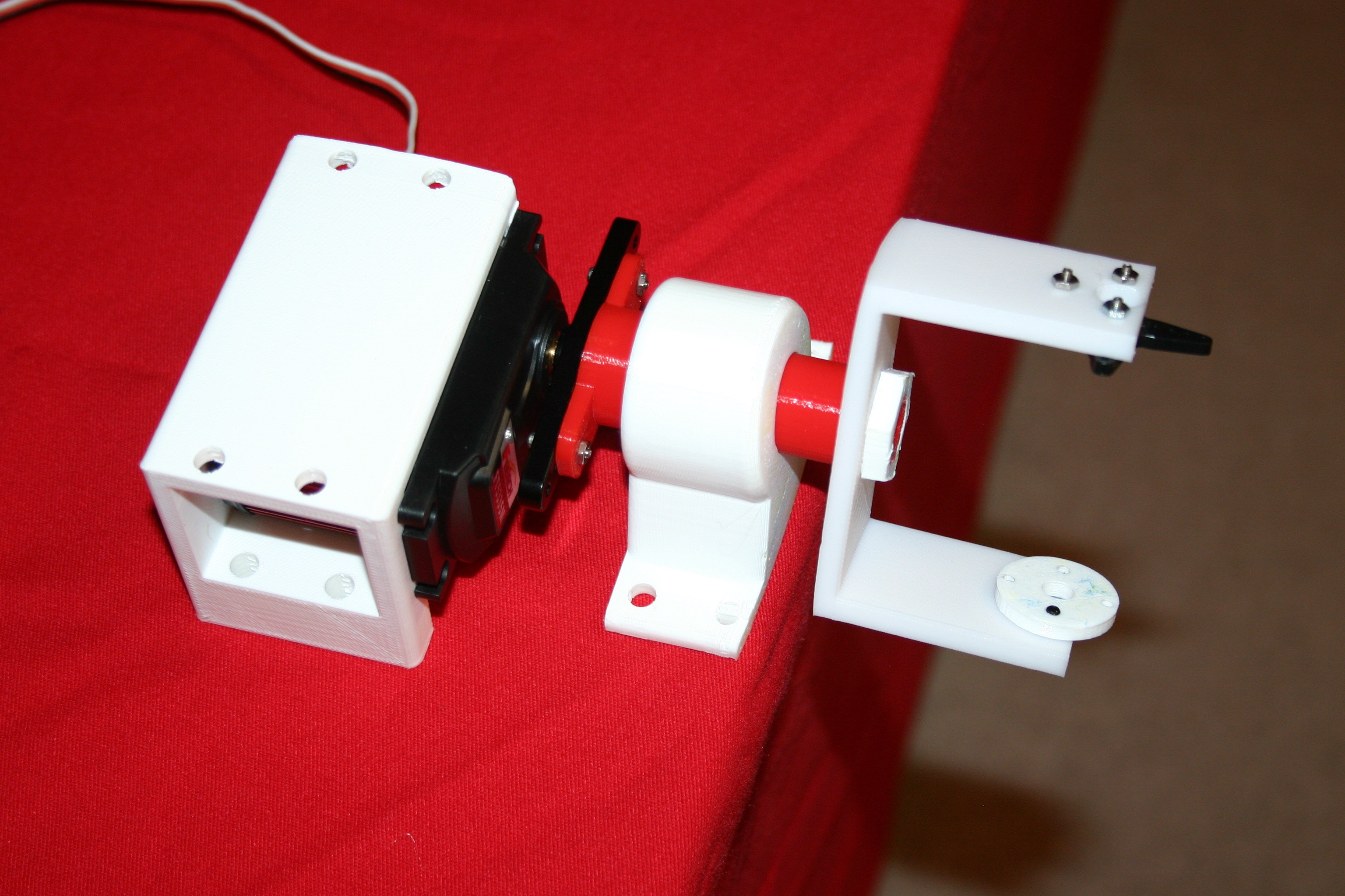
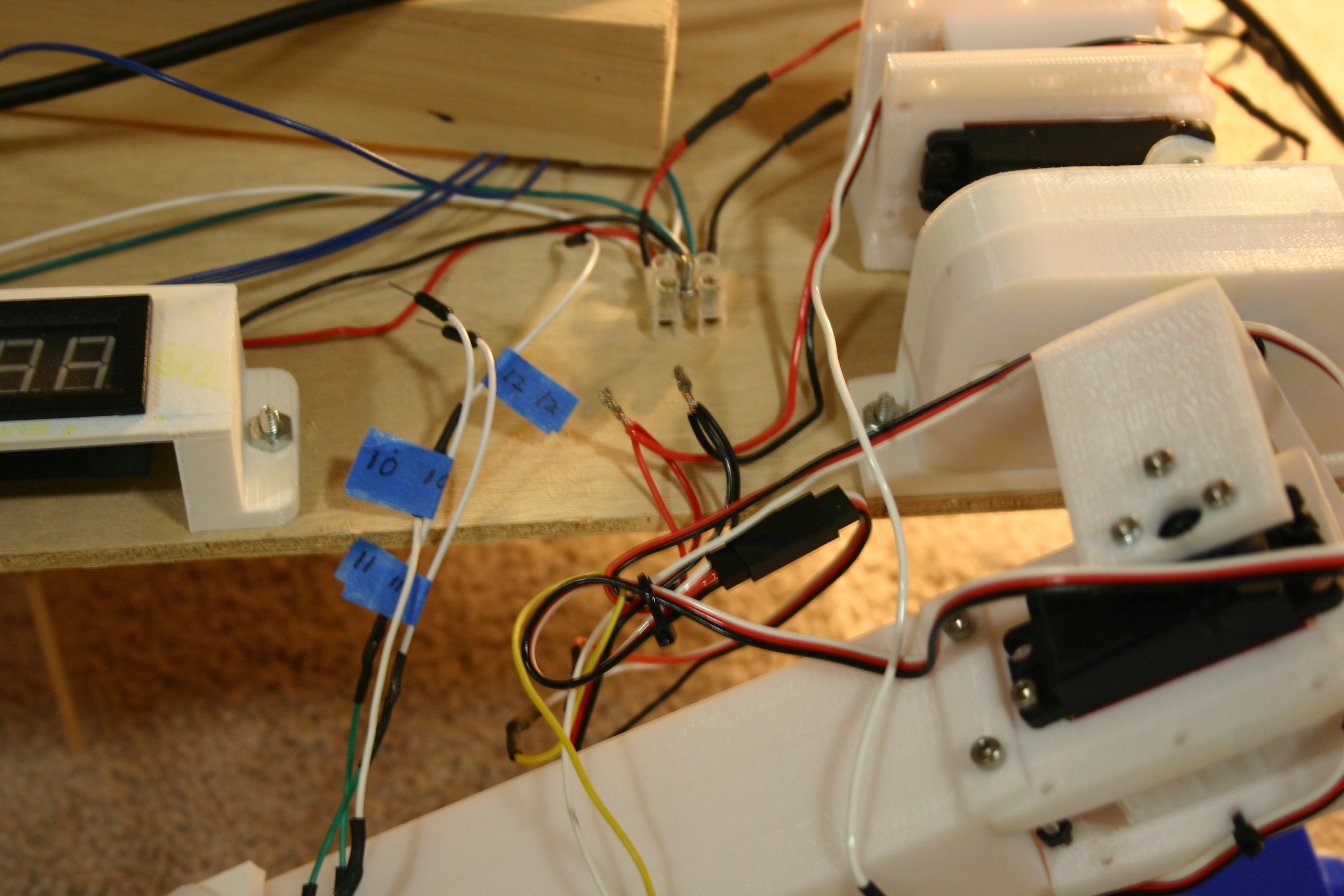
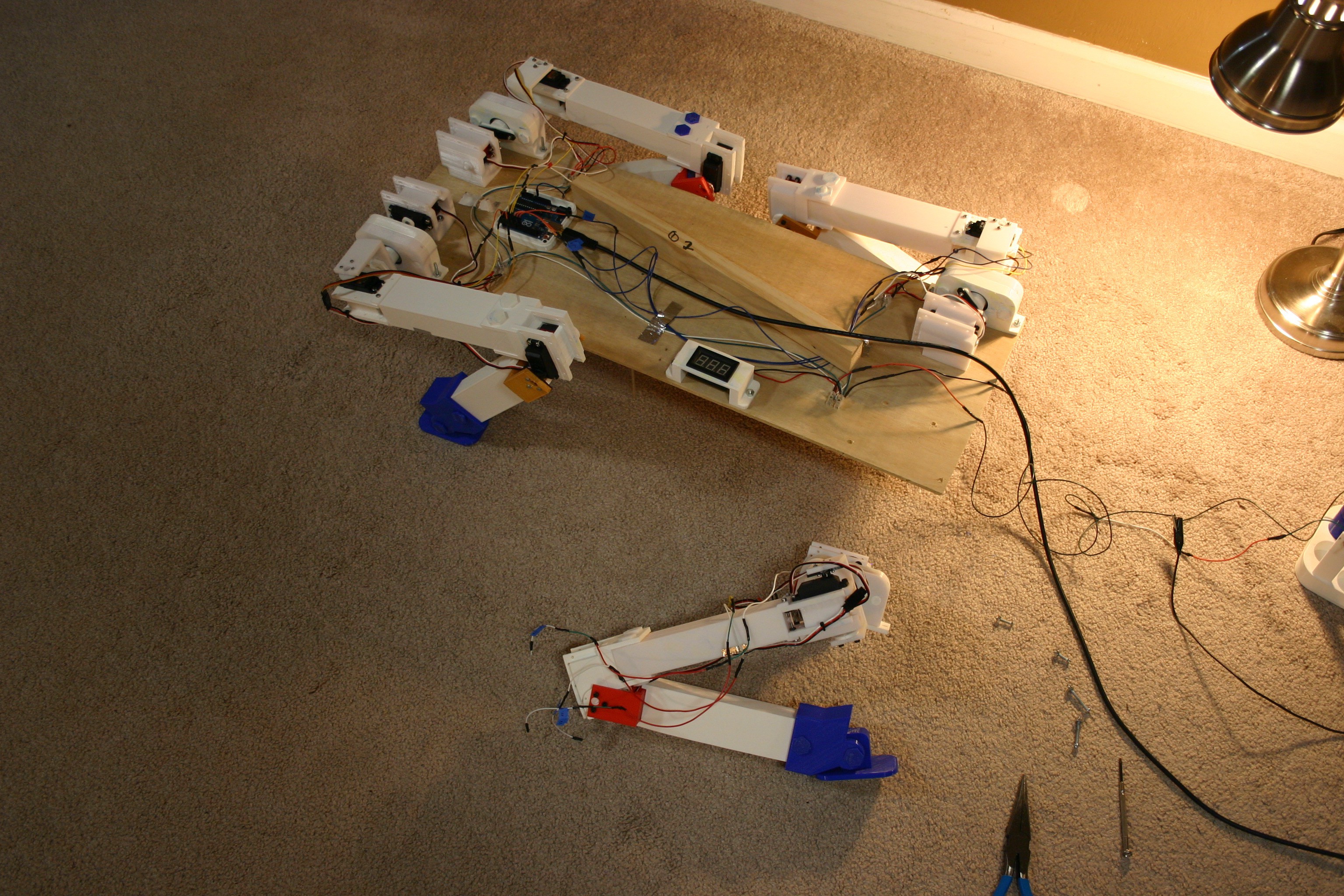
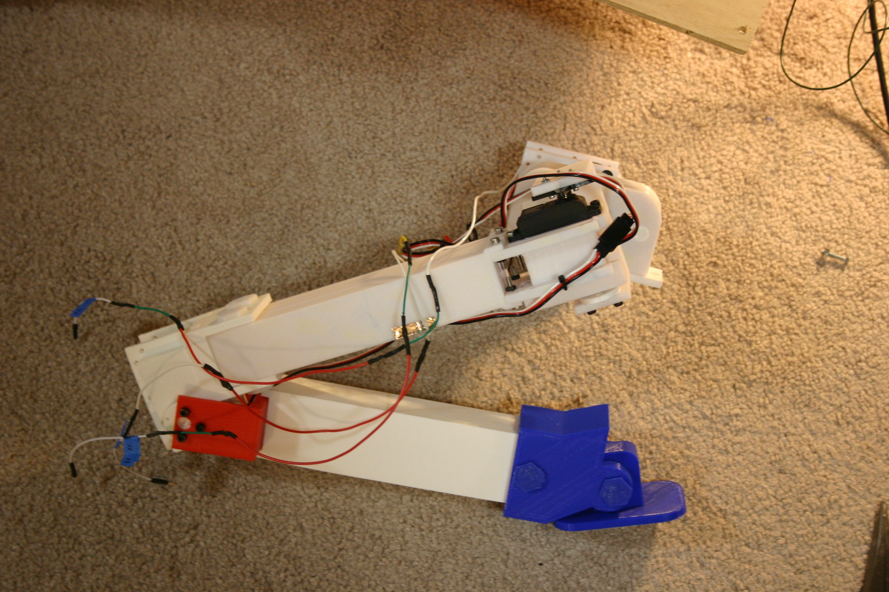
03/26/2019 at 19:47 • 1 commentI decreased the length of the legs to reduce stress on the printed parts while allowing the motors to work more reliably.
-
Onboard Power
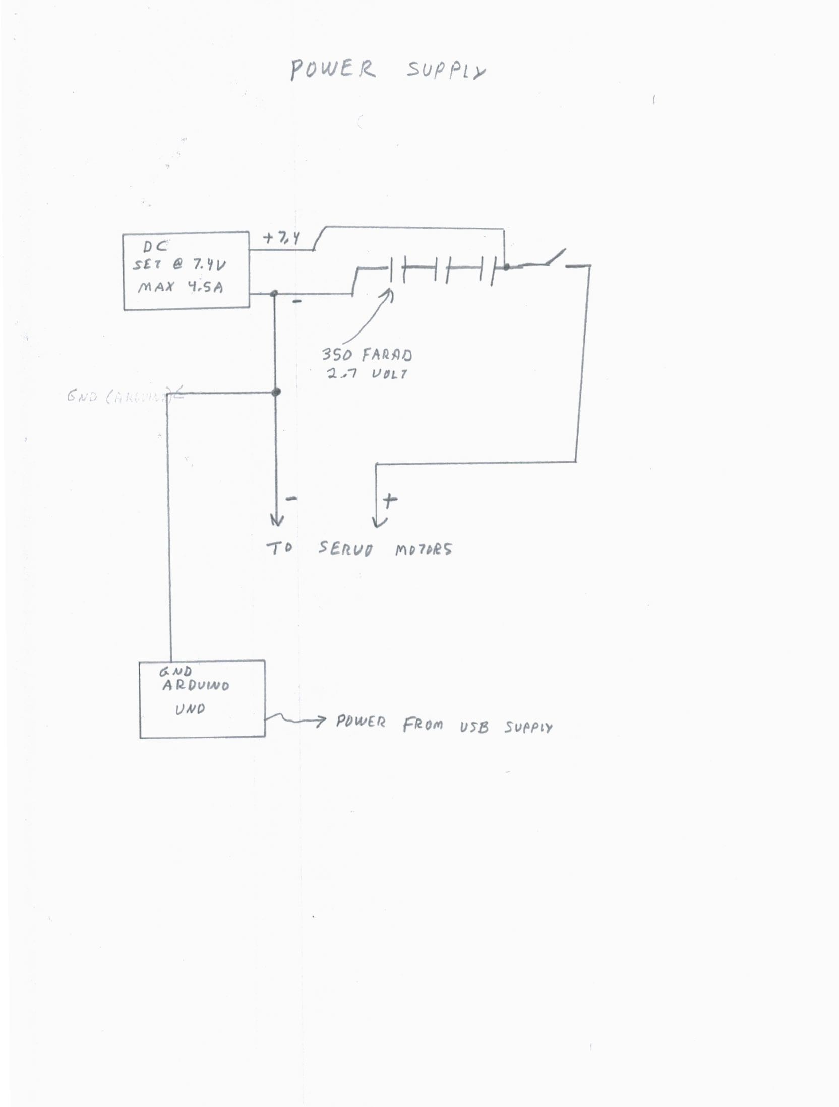
06/27/2018 at 19:37 • 2 commentsLet's start with a schematic of the power supply.
![]()
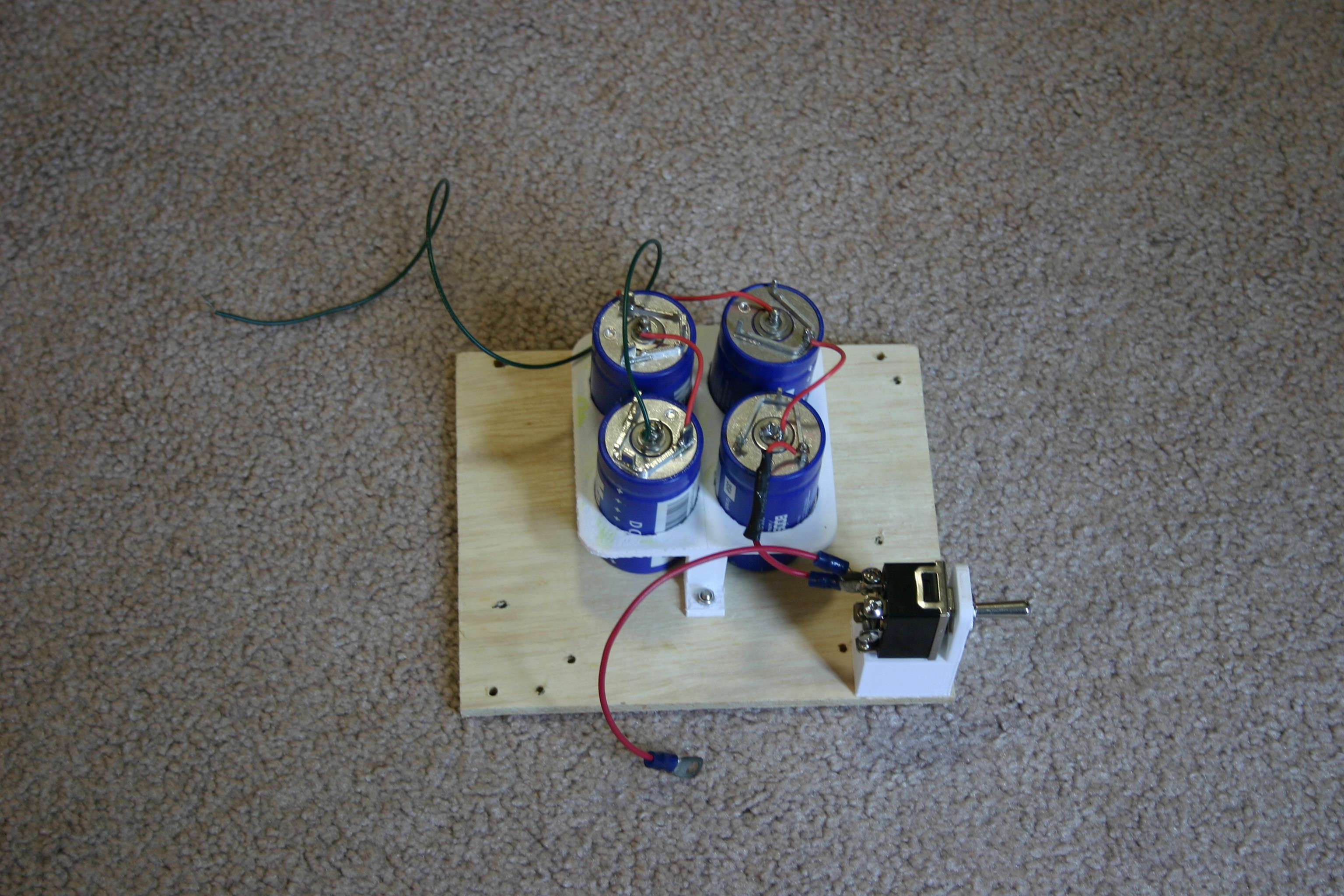
This supply is built on a piece of 5 1/4" x 6 1/4" plywood (1/4" thick). The four 350 farad capacitors are soldered together in series, then placed in the 3d printed capacitor holder.
![]()
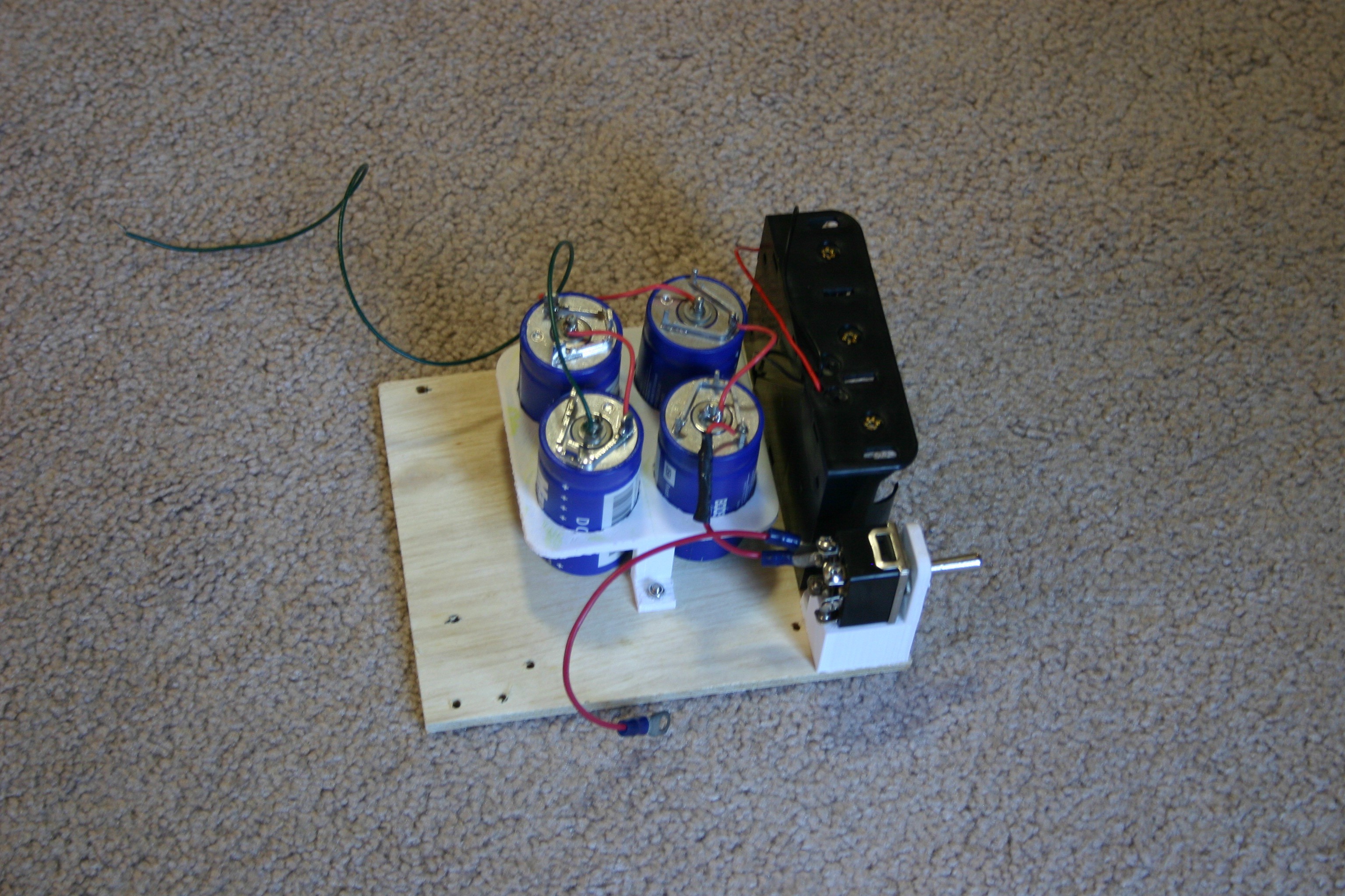
A "three cell" D battery holder is added.
![]()
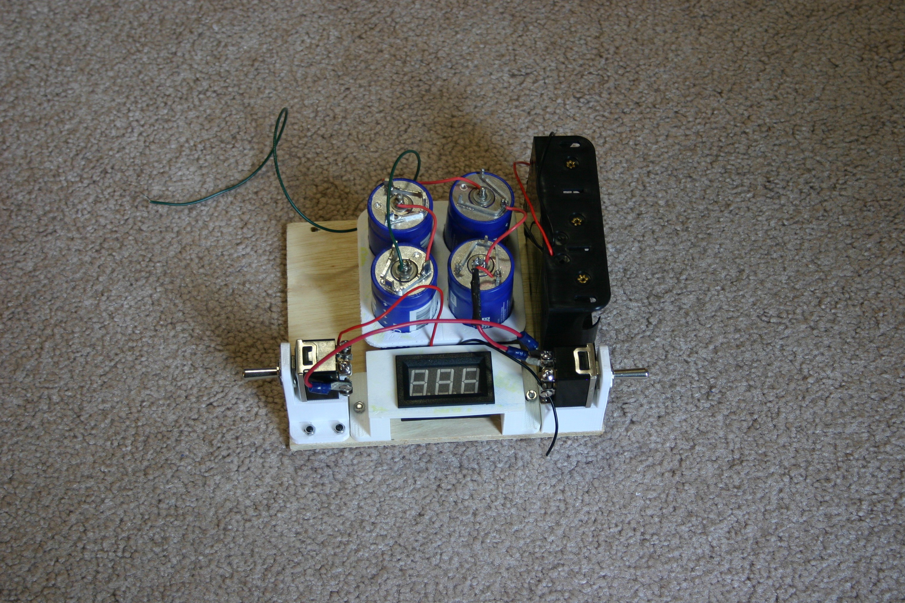
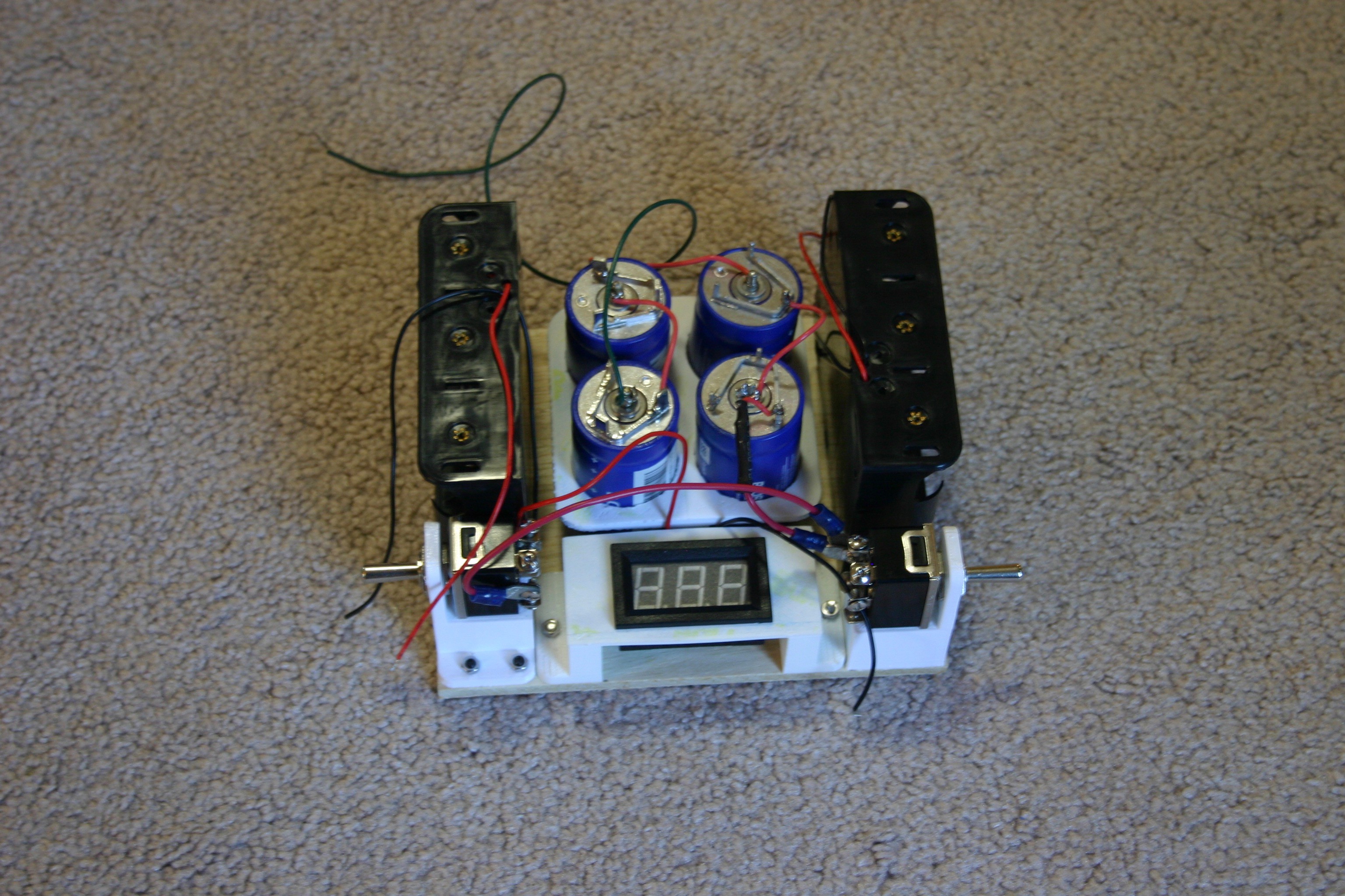
The second toggle switch and digital voltmeter are added.
![]()
The second "3 D cell battery holder" is added.
![]()
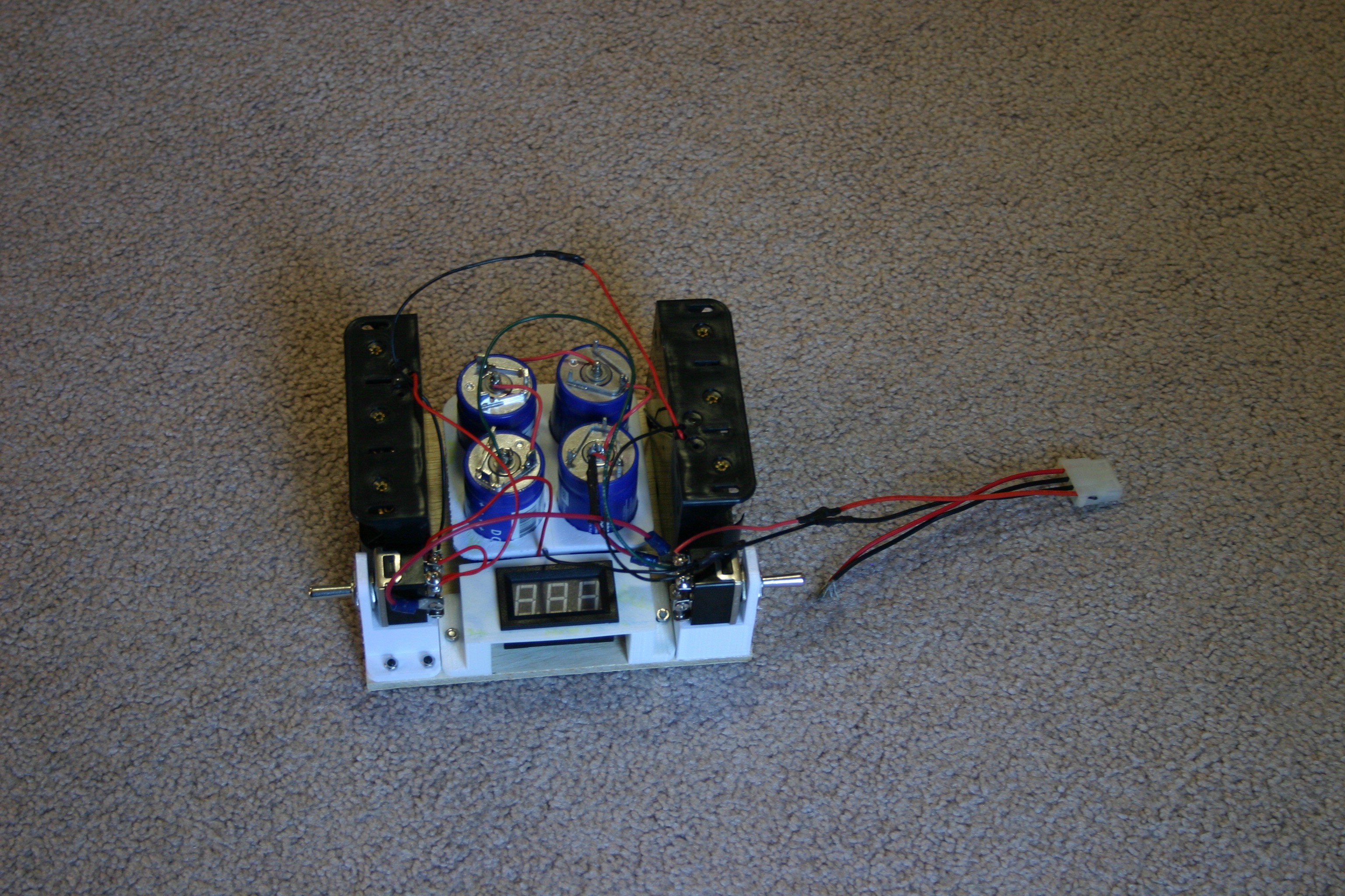
Everything is connected and wired out to a plug that can attach to the dog's body.
![]()
The 9 volt battery holder (with built in switch) and the battery/capacitor power supply are attached to the body using velcro.
![]()
Because the dog was tired of being inside, I took her out for a little air.
-
Non Slip Joint
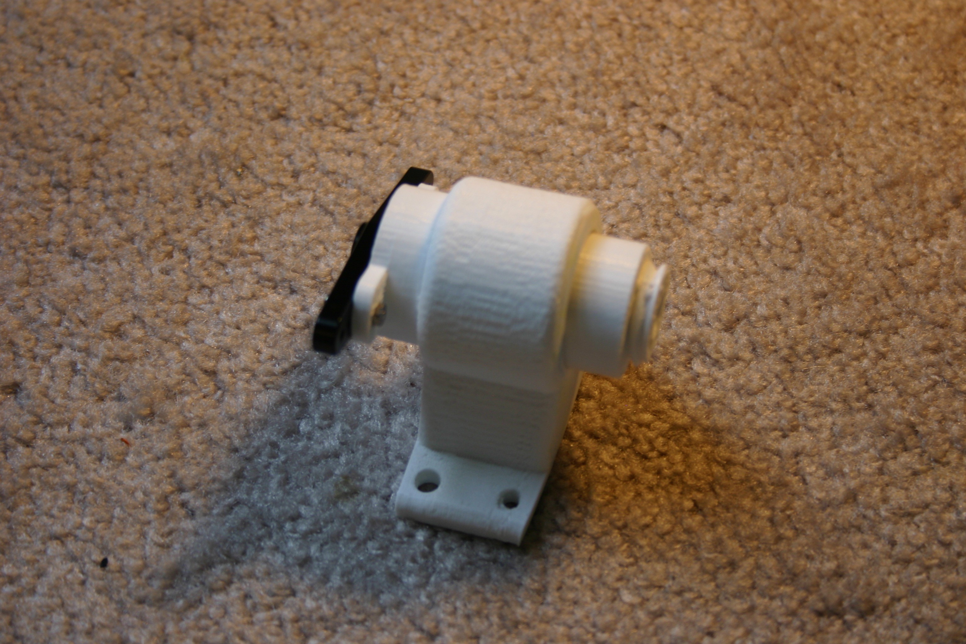
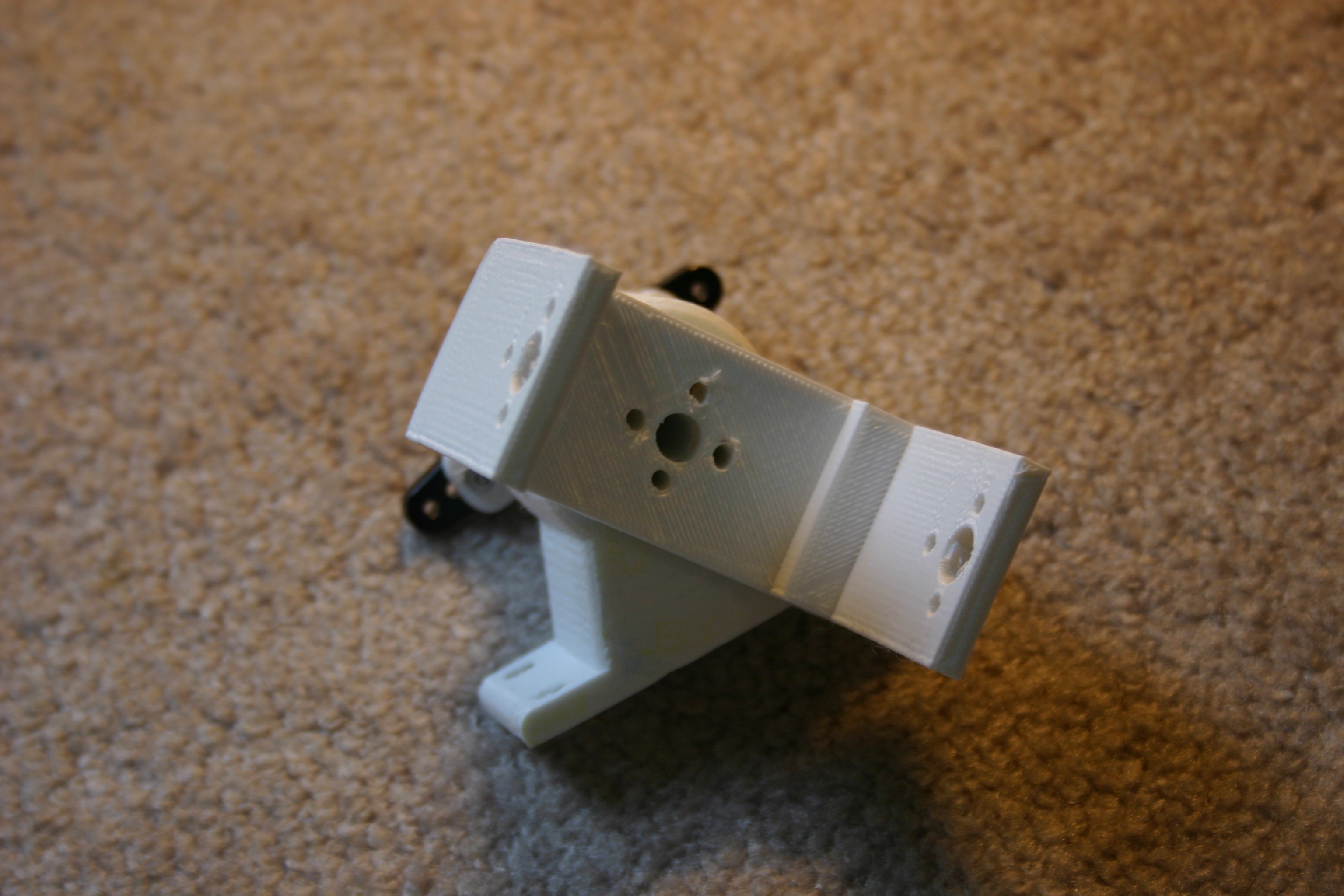
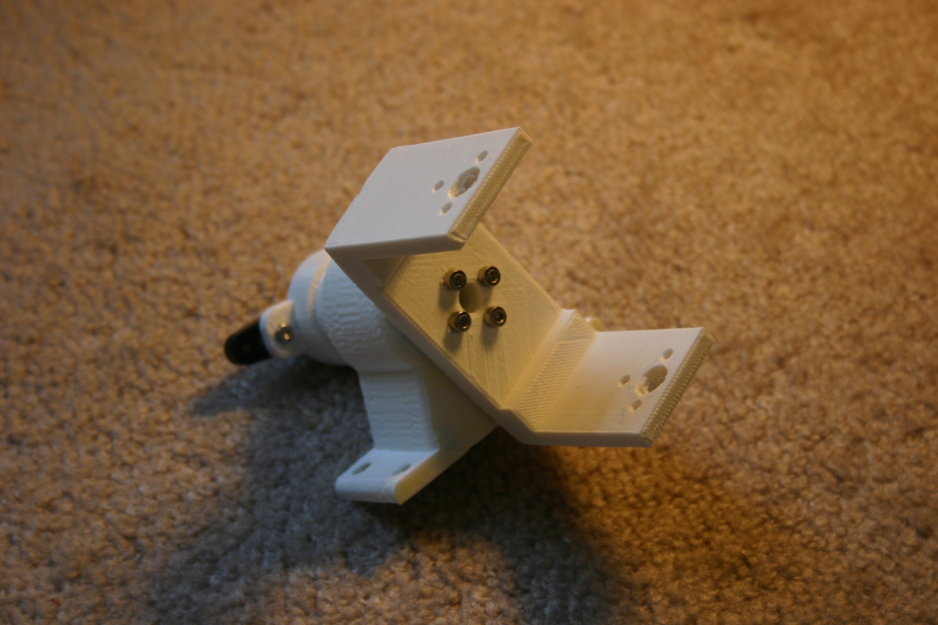
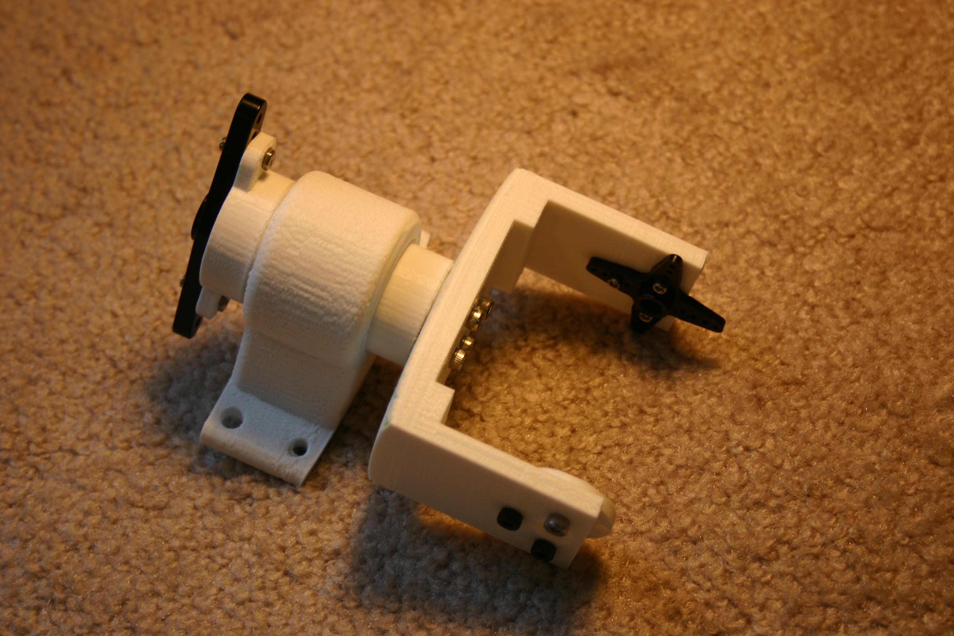
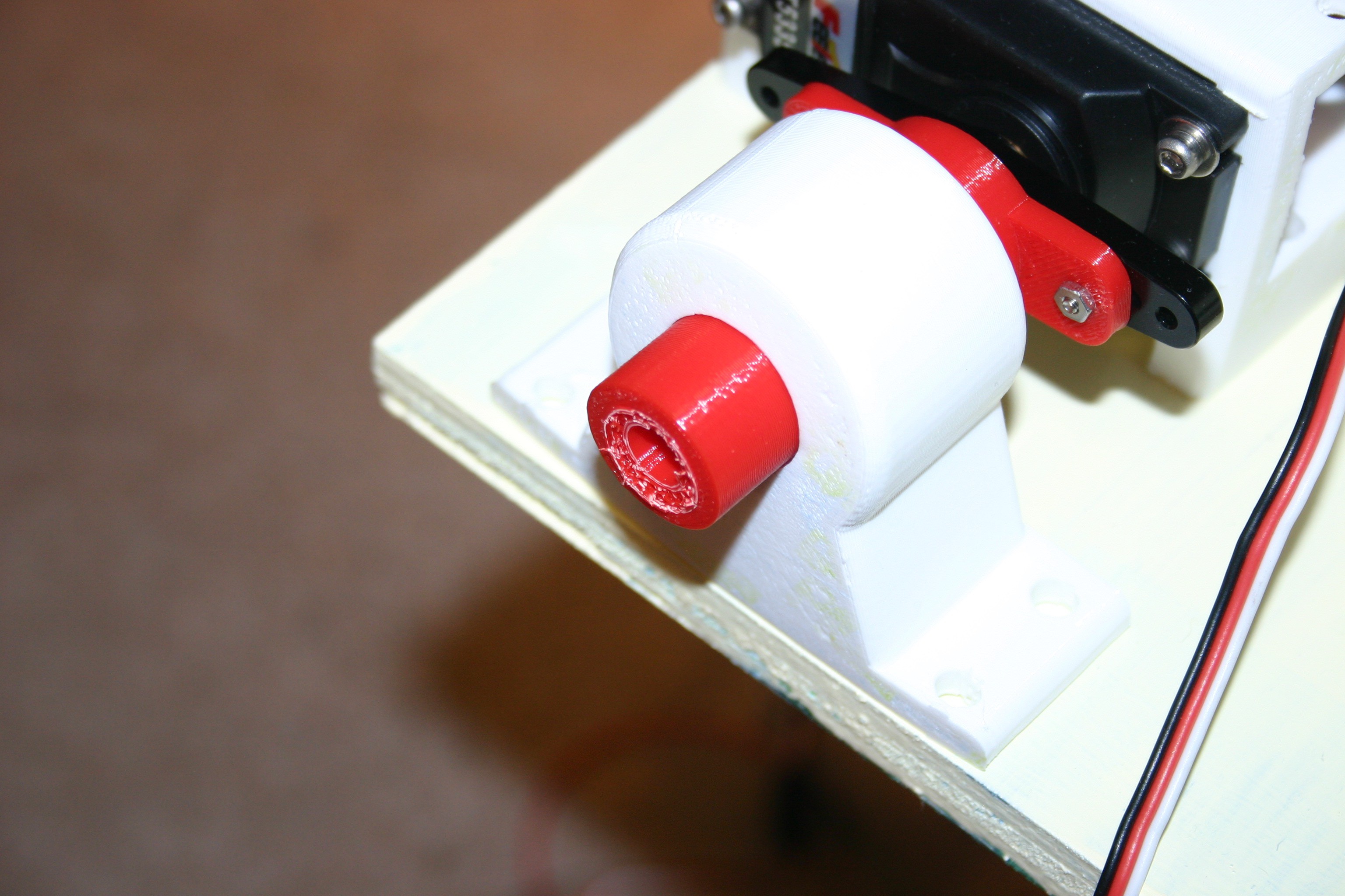
06/22/2018 at 13:15 • 0 commentsIn the upper leg joint--in spite of all my best efforts at making the joint tight--I continue to have slipping. To correct this, I modified the joint, inserting machine screws to prevent slippage.
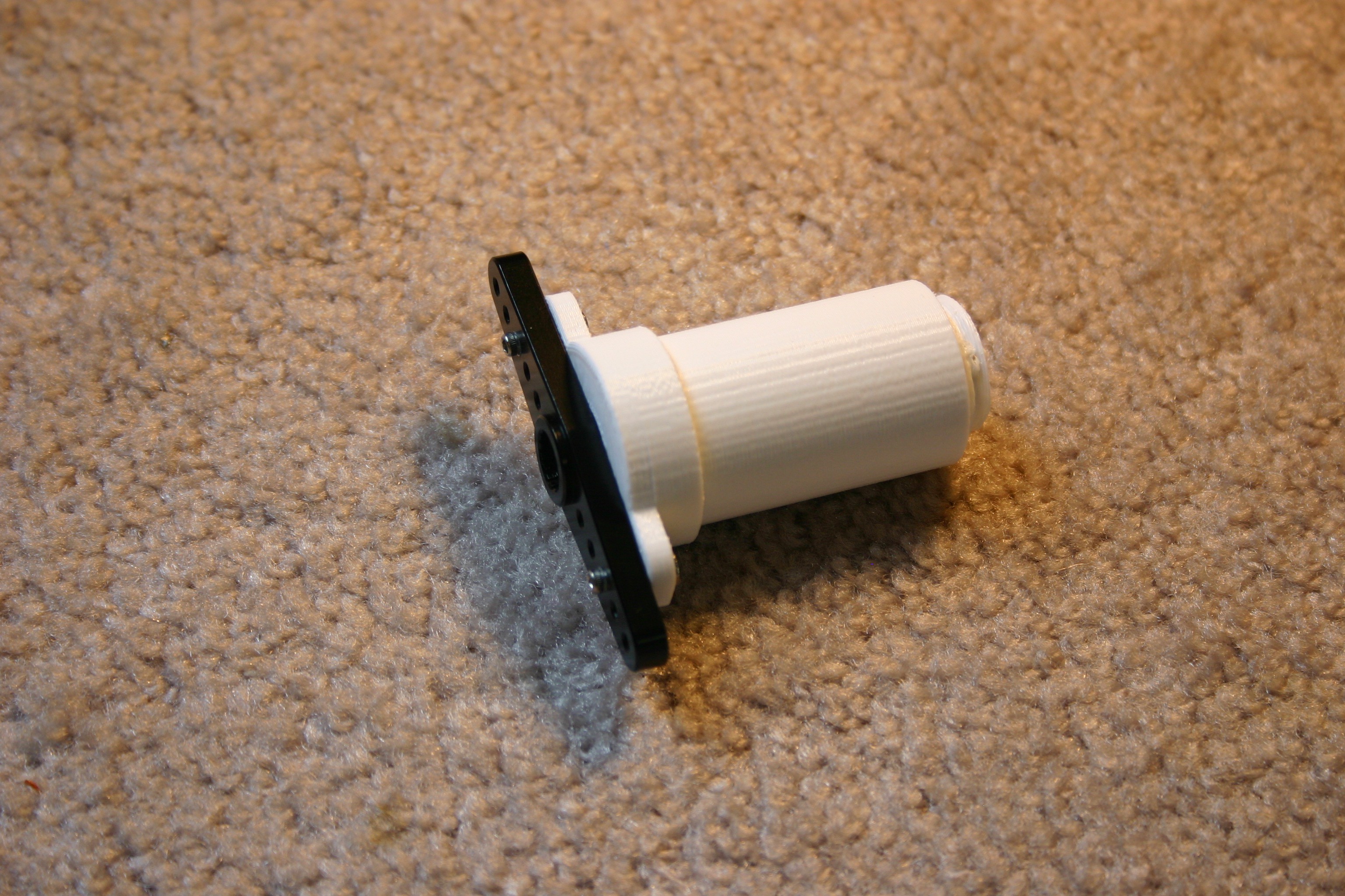
I printed (4) axles with shorter threads, then attached the servo horns.
![]()
I slide this piece ("axle shorter thread") through "bearing linearb."
![]()
Thread "fat pieceb" onto this.
![]()
Drill holes 25 mm deep using a 7/64 inch drill bit. Install (4) 20 mm M3 machine screws.
![]()
Add the servo horn and back bearing piece, then install on all four legs.
![]()
This is a significant operation requiring about 20 hours of print time and 8 hours of installation time.
-
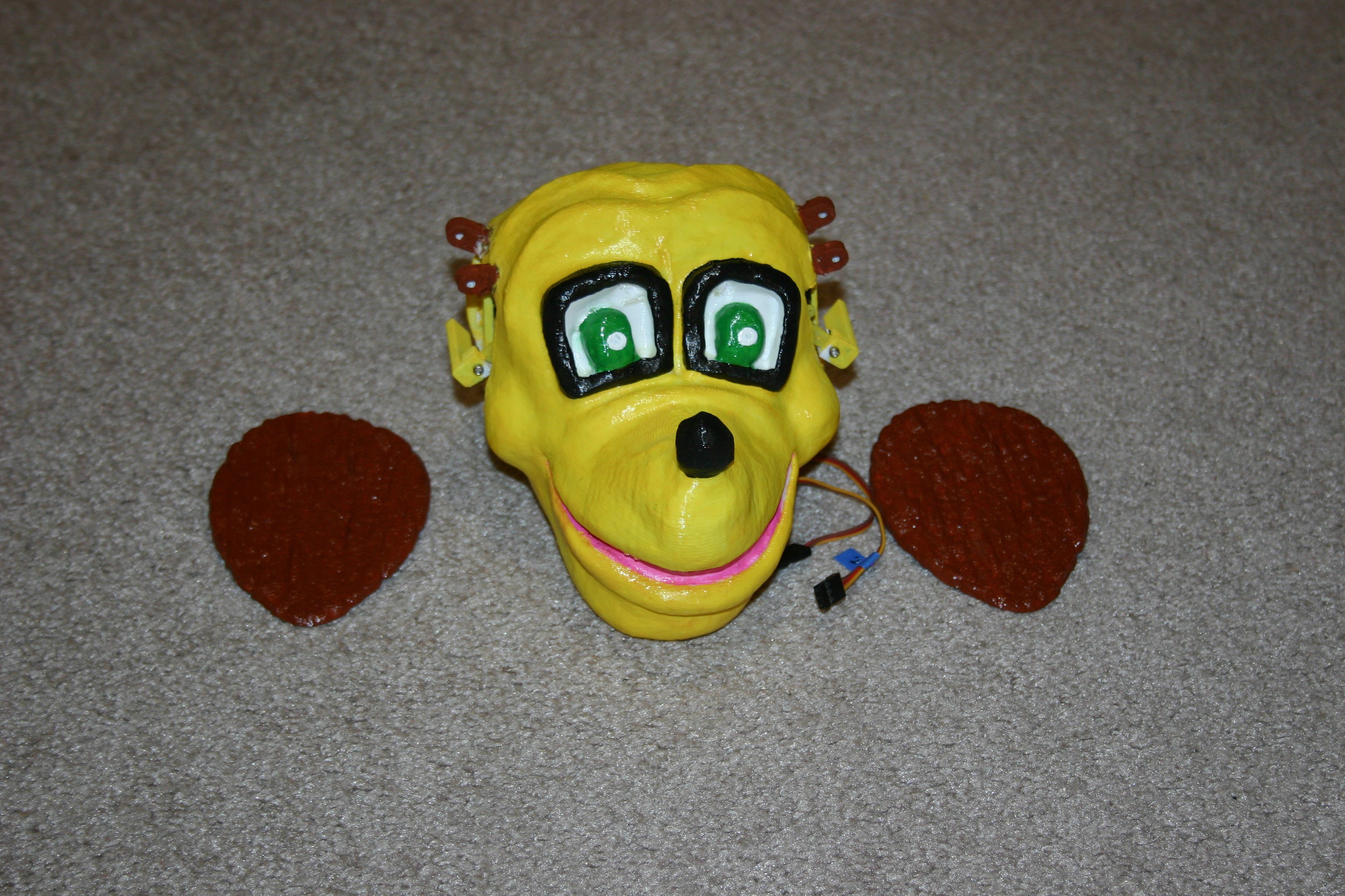
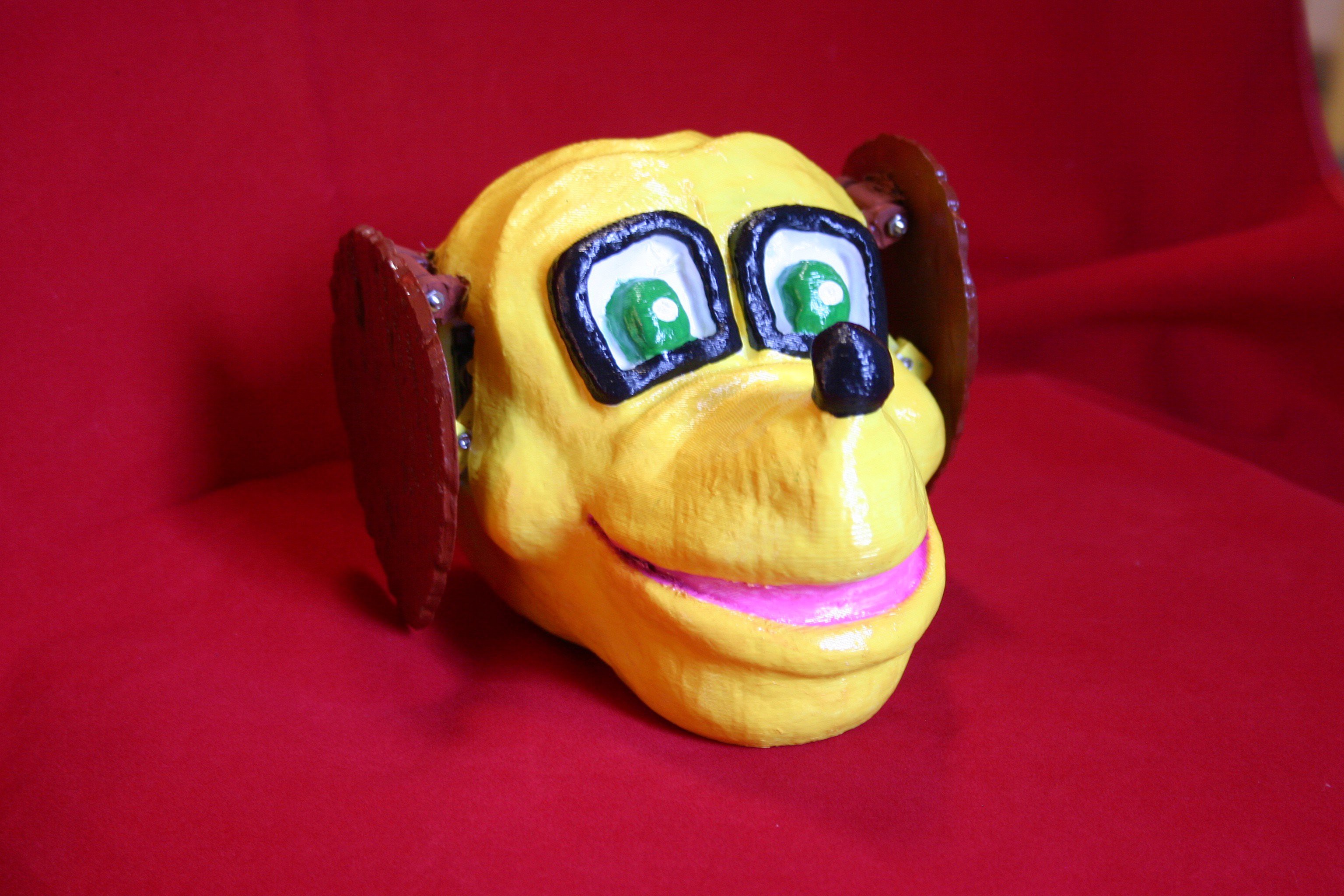
Dog's Head
06/03/2018 at 20:12 • 0 commentsHere's the first version of a head--with flapping ears synchronized to barks.
I don't have a dog, so we had to visit a friend and record their dog's bark. Of course, Juston (the dog) just stood silently for all the many things that normally trigger a bark (treat, knock on the door, promise of a car ride). Finally, he was induced to talk.
This "Dog Head Module" is a 3d printed head with two servo motors that can be used to flap ears. It can be added to any dog robot (wheels or legs) and modified (the raw head files are available on this site).
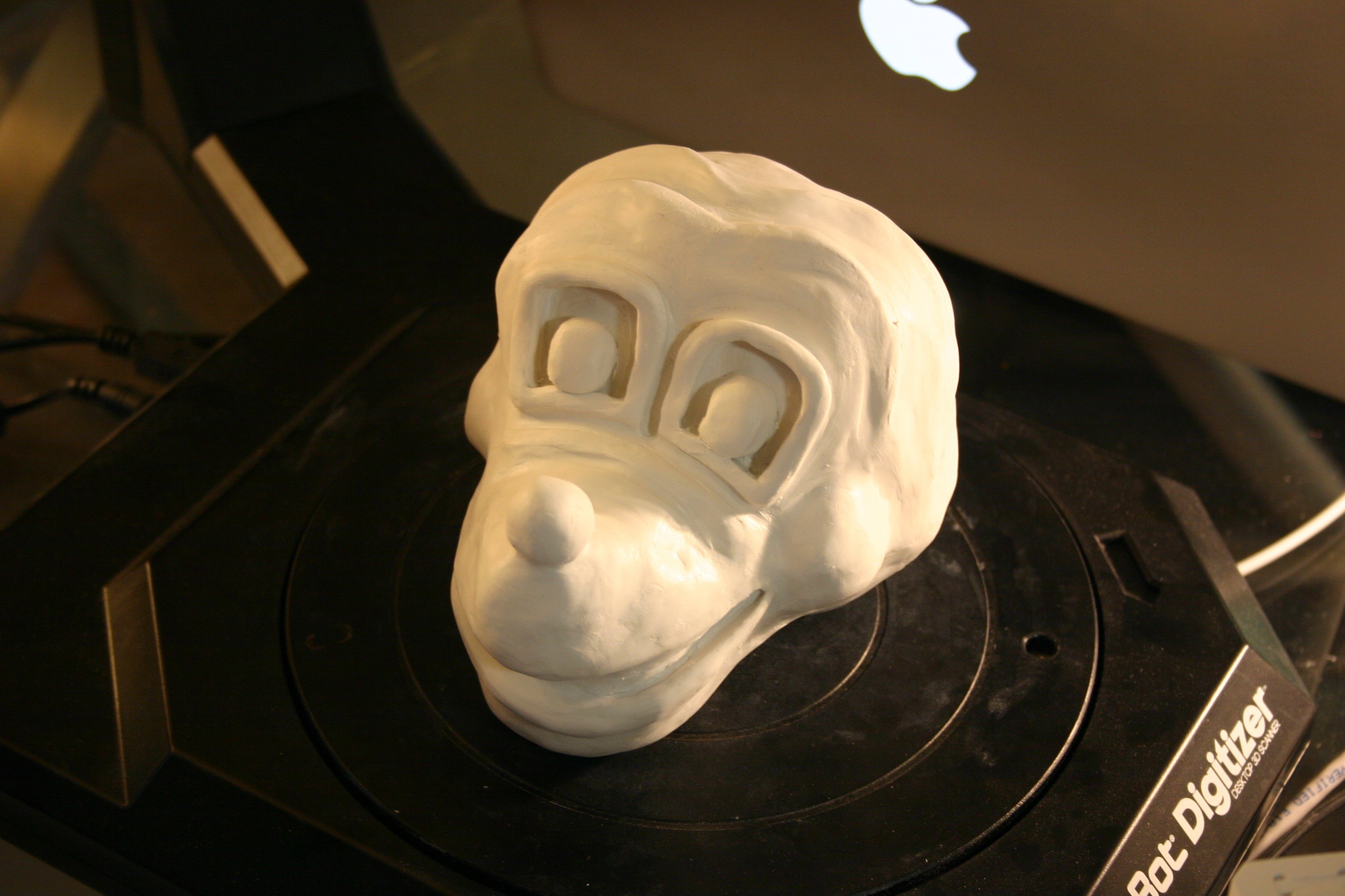
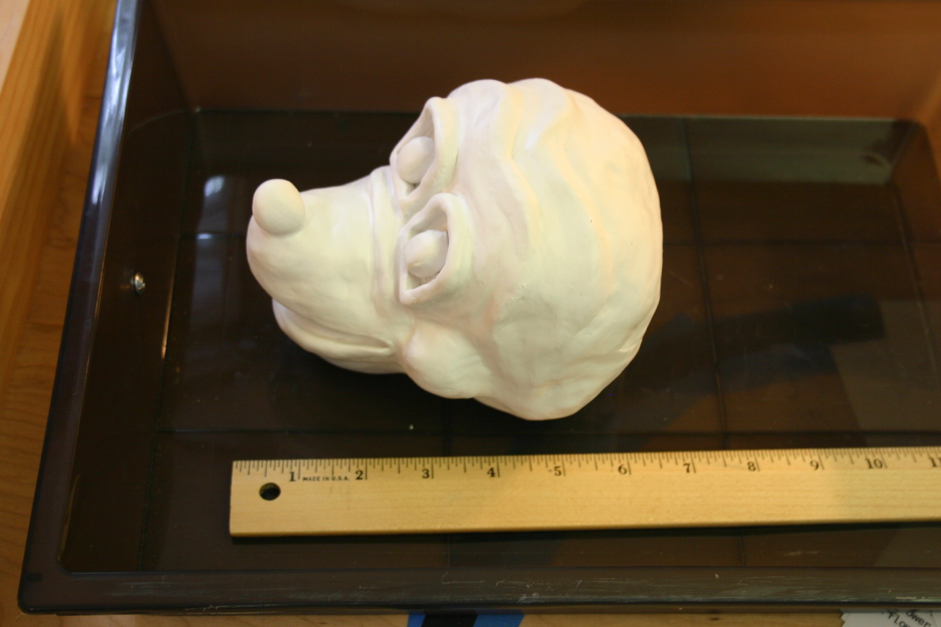
My wife, Annelle, made a clay head for scanning.
![]()
The head is fairly large and was scanned on a Makerbot Digitizer.
![]()
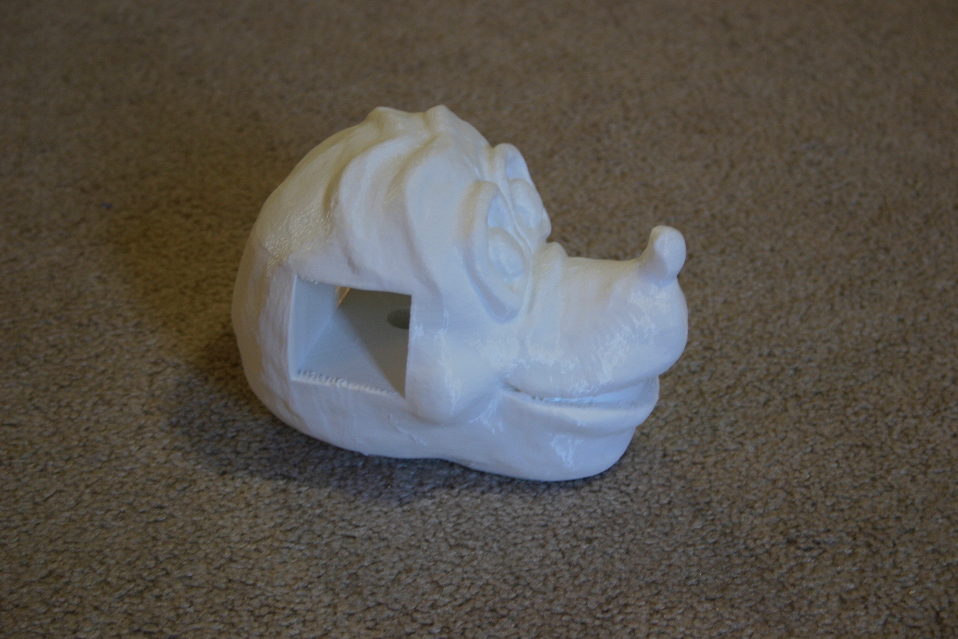
The resulting scan file (included) was too large to import into Tinkercad. I reduced the file size (included) then imported the head into Tinkercad and made holes for the servo motors and wires.
![]()
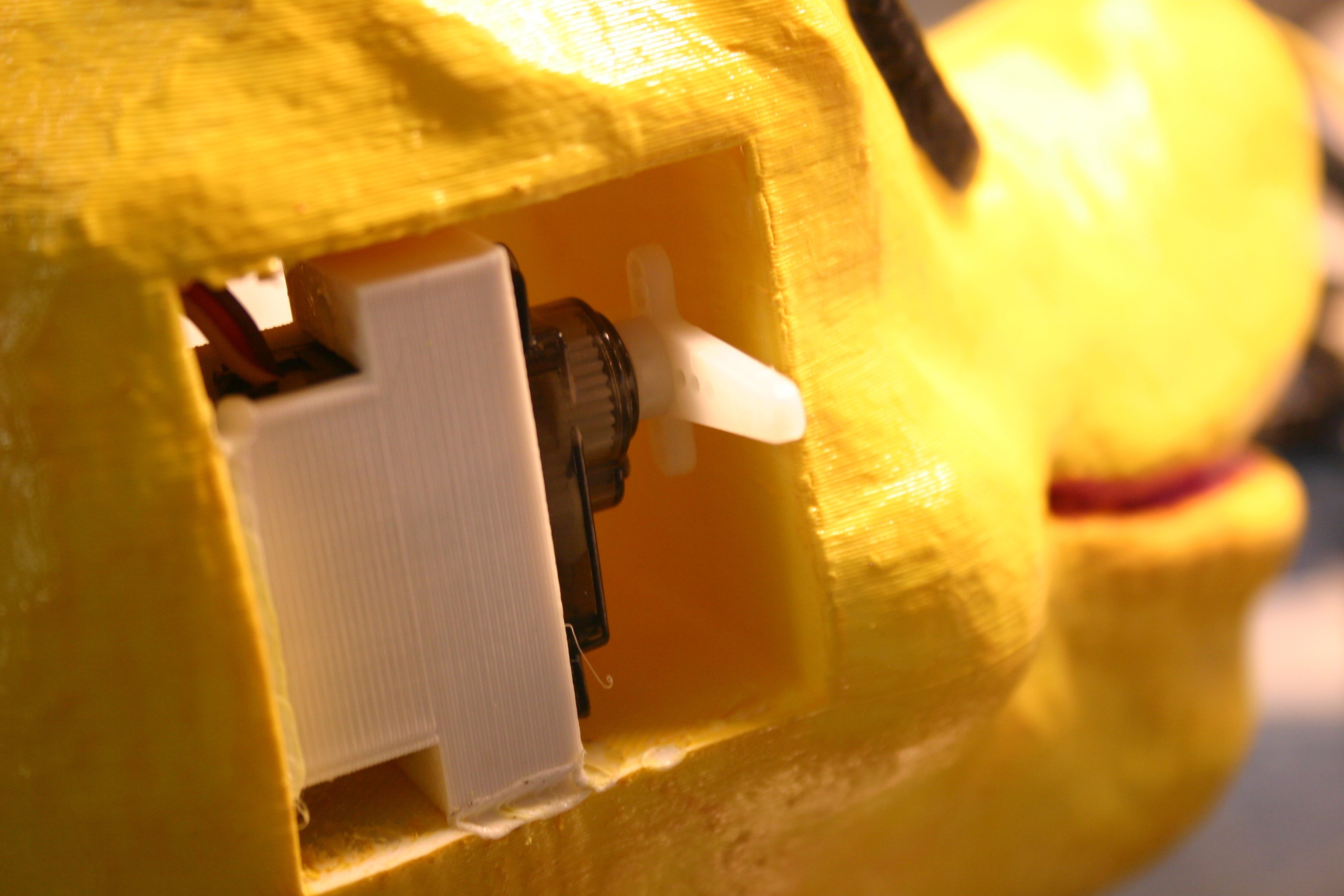
I mounted the micro servo motors in their 3d printed brackets, then melted (using a soldering iron) the bracket into the head.
![]()
I added a servo horn extender to the servo horn so that the ear would move a reasonable amount.
![]()
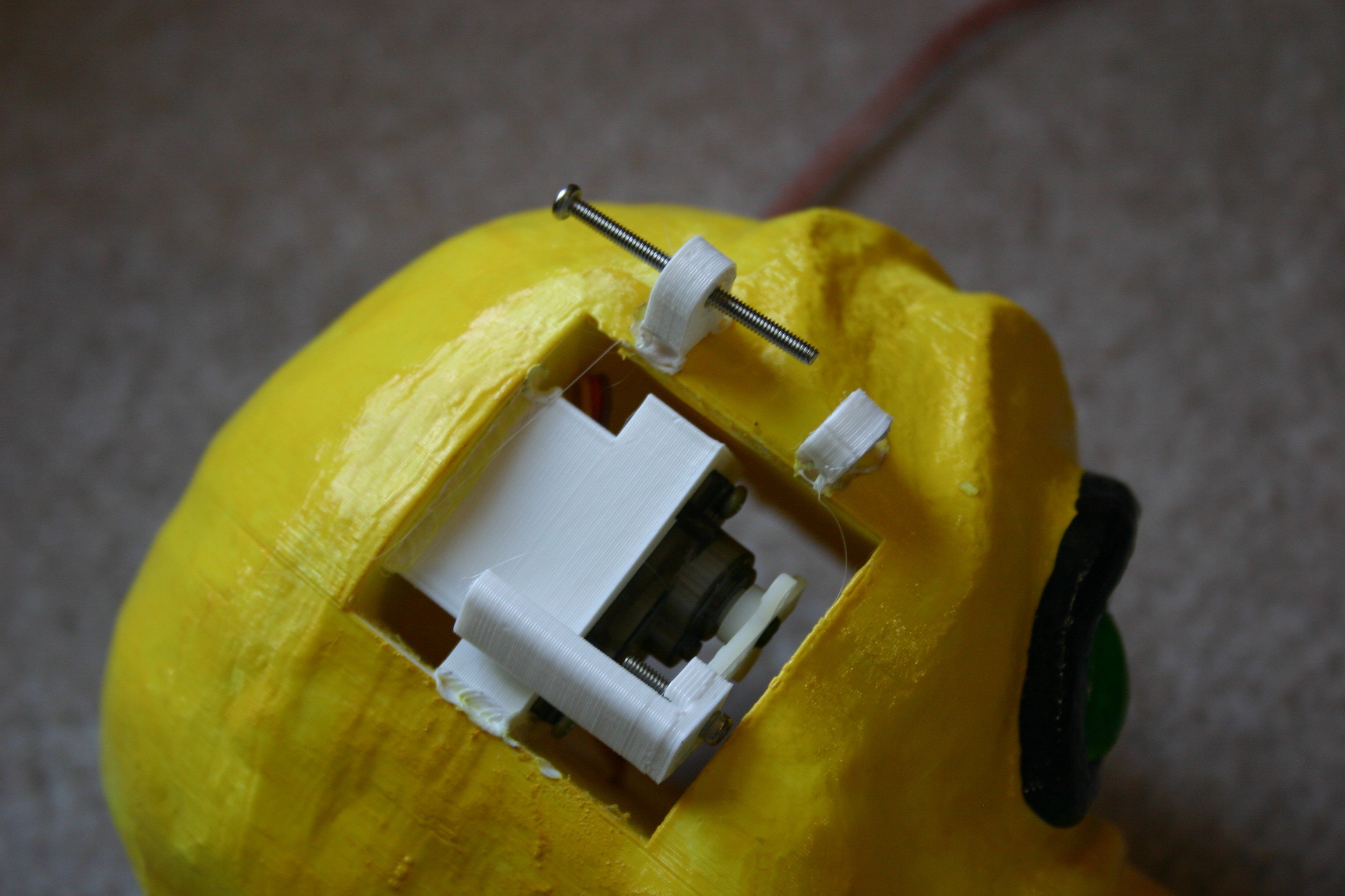
Bearing brackets (3d printed) were melted onto the dog's head. They accommodate the 1 1/4 inch by 2-56 machine screws that allow the ear to move.
![]()
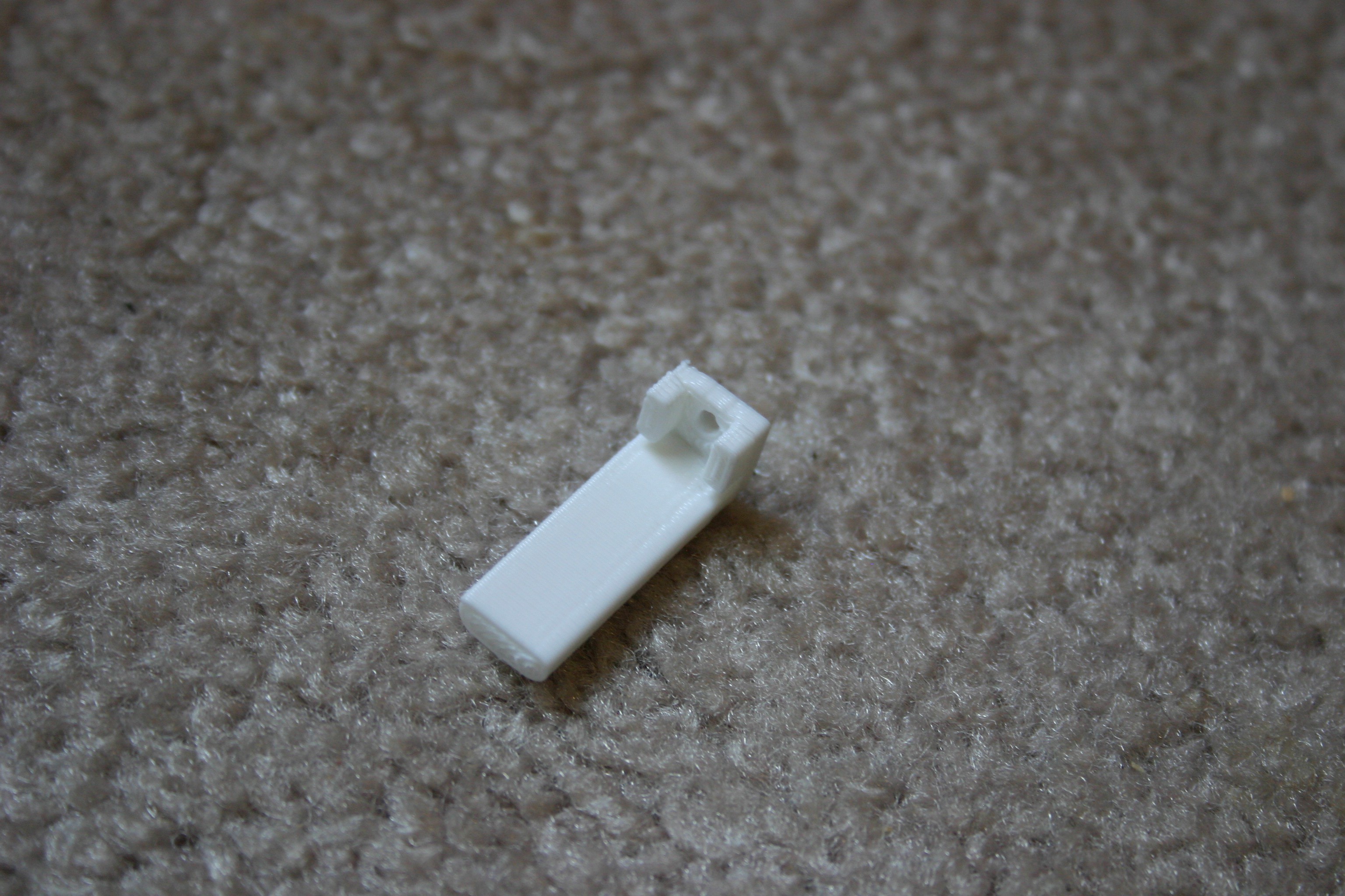
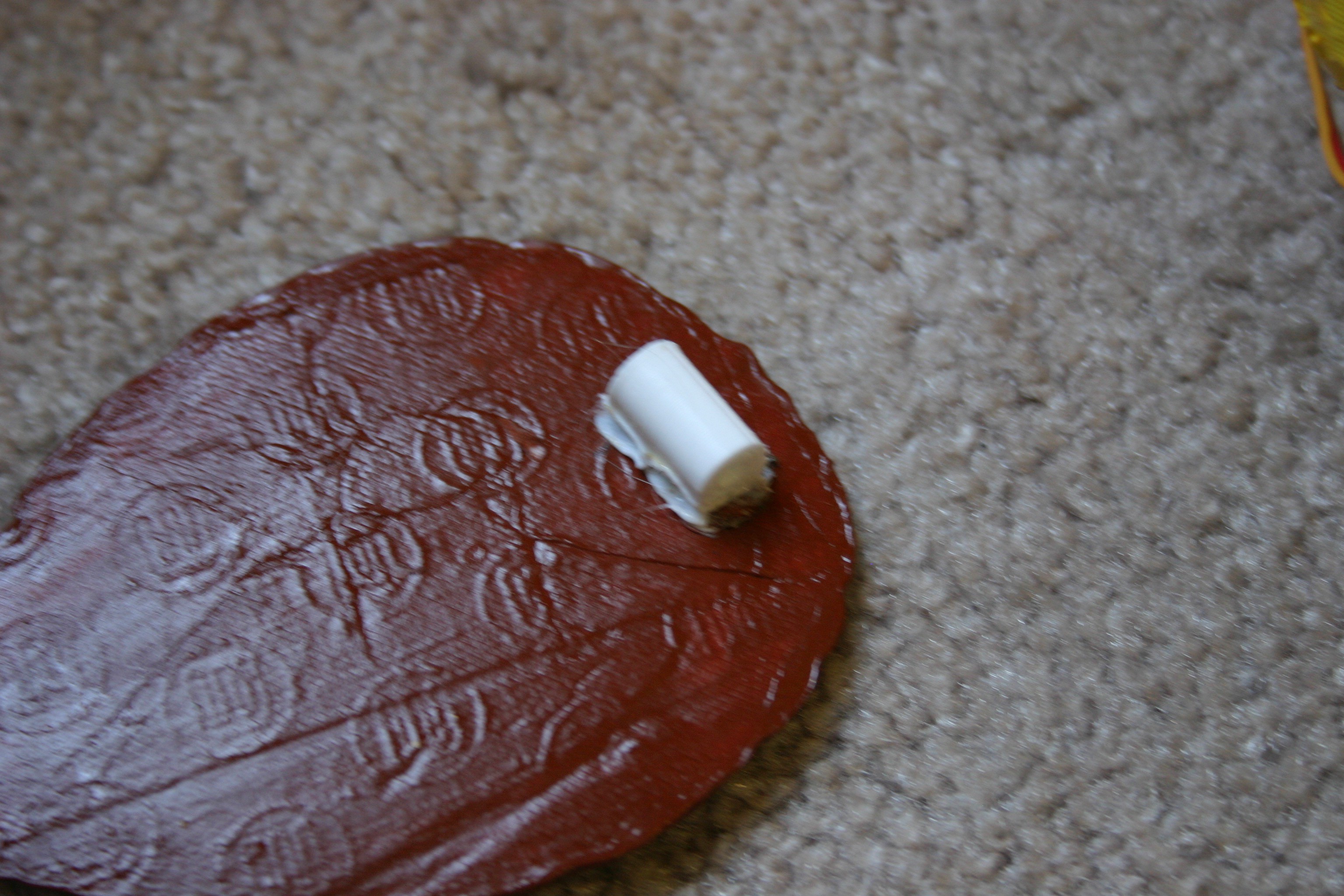
A bearing adapter piece must be melted to each ear.
![]()
A finished (not painted) ear looks like this.
![]()
Back to the art shop (Annelle) for a paint job.
![]()
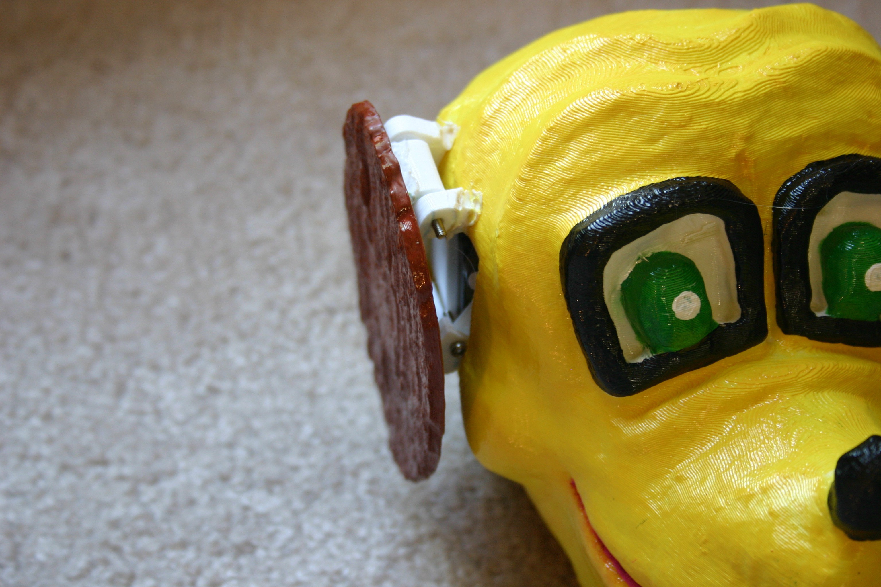
Assembled, the head looks like this.
![]()
I used an Adafruit sound module board and trigger the bark file (included on this site) with an Arduino. I coordinated the ear flapping servo motors with the bark sound.
You could put square 8x8 led modules in for the eyes. The mouth could be cut away and modified to move for the bark . . . this is just a starting place.
-
Tilt Module
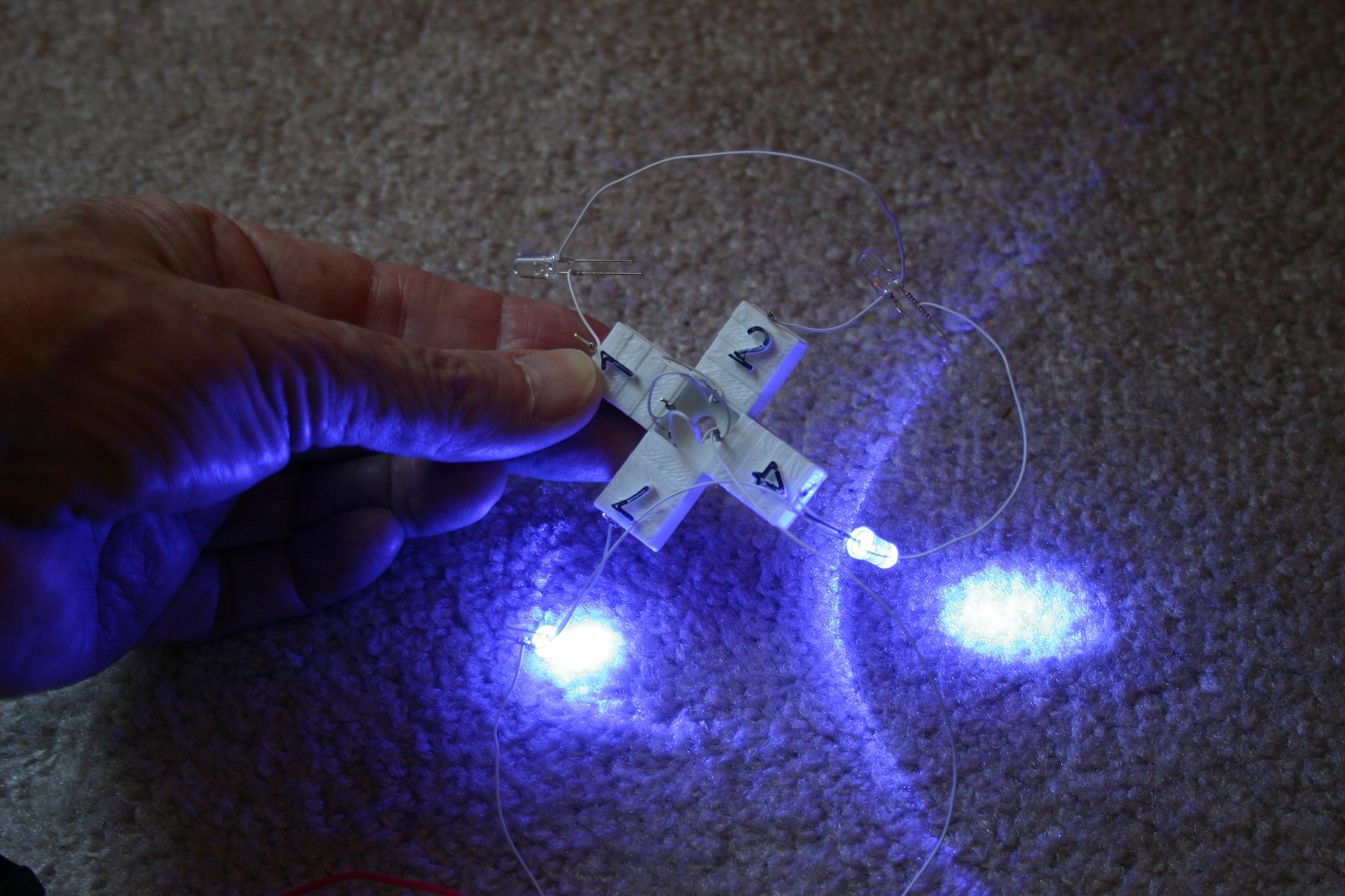
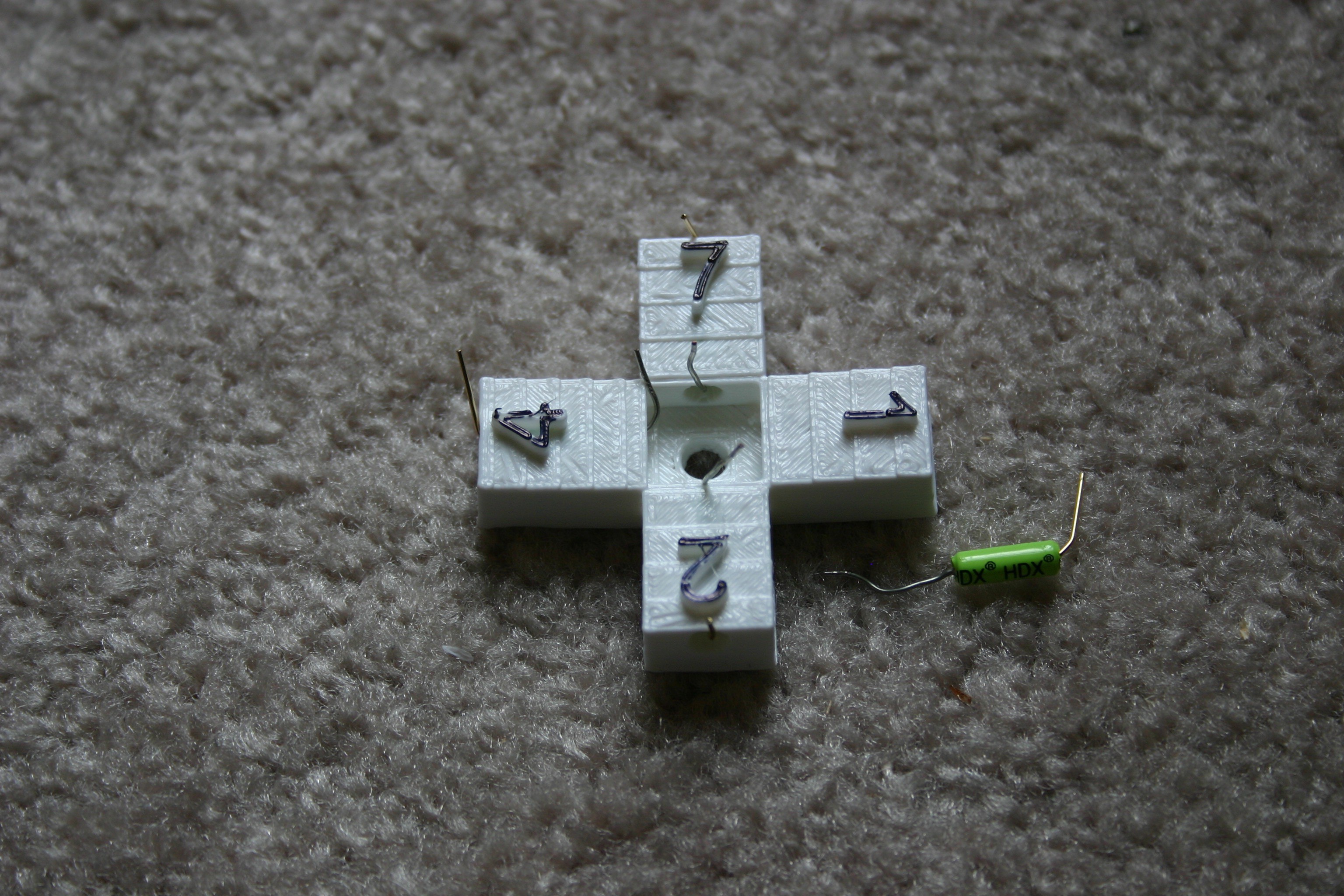
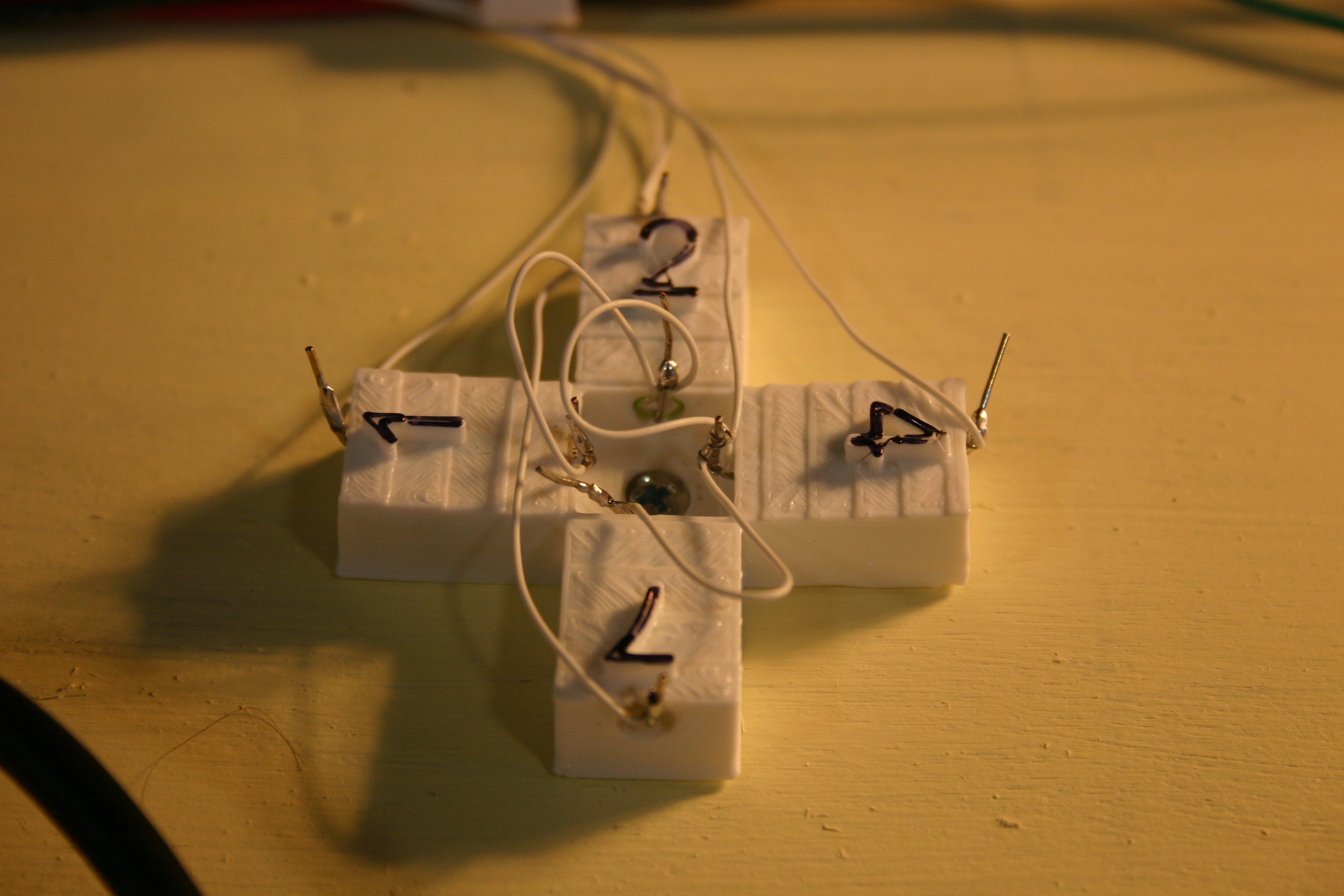
05/25/2018 at 20:27 • 0 commentsThis low cost module using four roller switches and a 3d printed bracket can be used to provide tilt information for a robot.
The idea is to use four roller ball tilt switches (about $.50 each from Amazon) and a 3d printed bracket to detect tilt. I designed a four degree tilt to each of the four "arms" so that the balls would roll downhill when the robot is level. By assigning the numbers "1" for north, "2" for east, "4" for south, and "7" for west it is possible to read each switch then add the numbers and know whether there is tilt and in what direction.
The leds shown below are just for testing--not part of the finished sensor.
![]()
I start with the tilt switch holder and insert the tilt switches. The "not active" end is pointed toward the center (longer wire, silver instead of brass). The "active" end--when lower than the other end--will result in continuity between the end wires.
![]()
I use wire wrap wire (then solder it) to connect the pins. The center position I tie to ground on the Arduino. Direction one goes to A0, direction two goes to A1, direction four goes to A2 and direction seven goes to A3 (since I used 12 Arduino Uno pins for servo control, I'm running low on input/output pins).
![]()
The final assembly, fastened to the dog using a wood screw, looks like this.
![]()
-
Wiring the Module for Power and Control
05/24/2018 at 19:55 • 2 commentsTo make the module stand requires power and control. Here's a schematic of the power components.
![]()
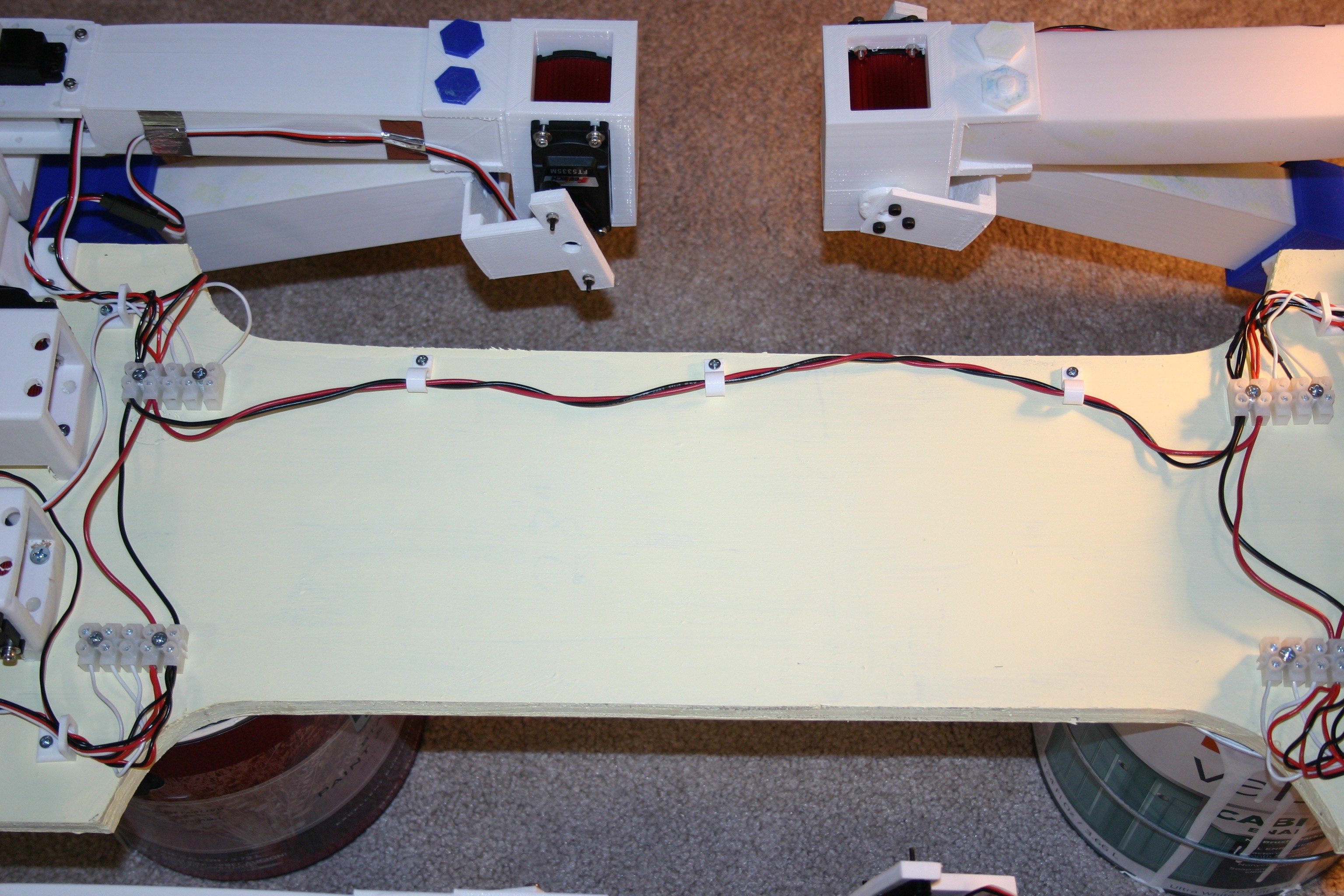
Let's look at the physical wiring. I connected the + and - power blocks using number 18 stranded wire.
![]()
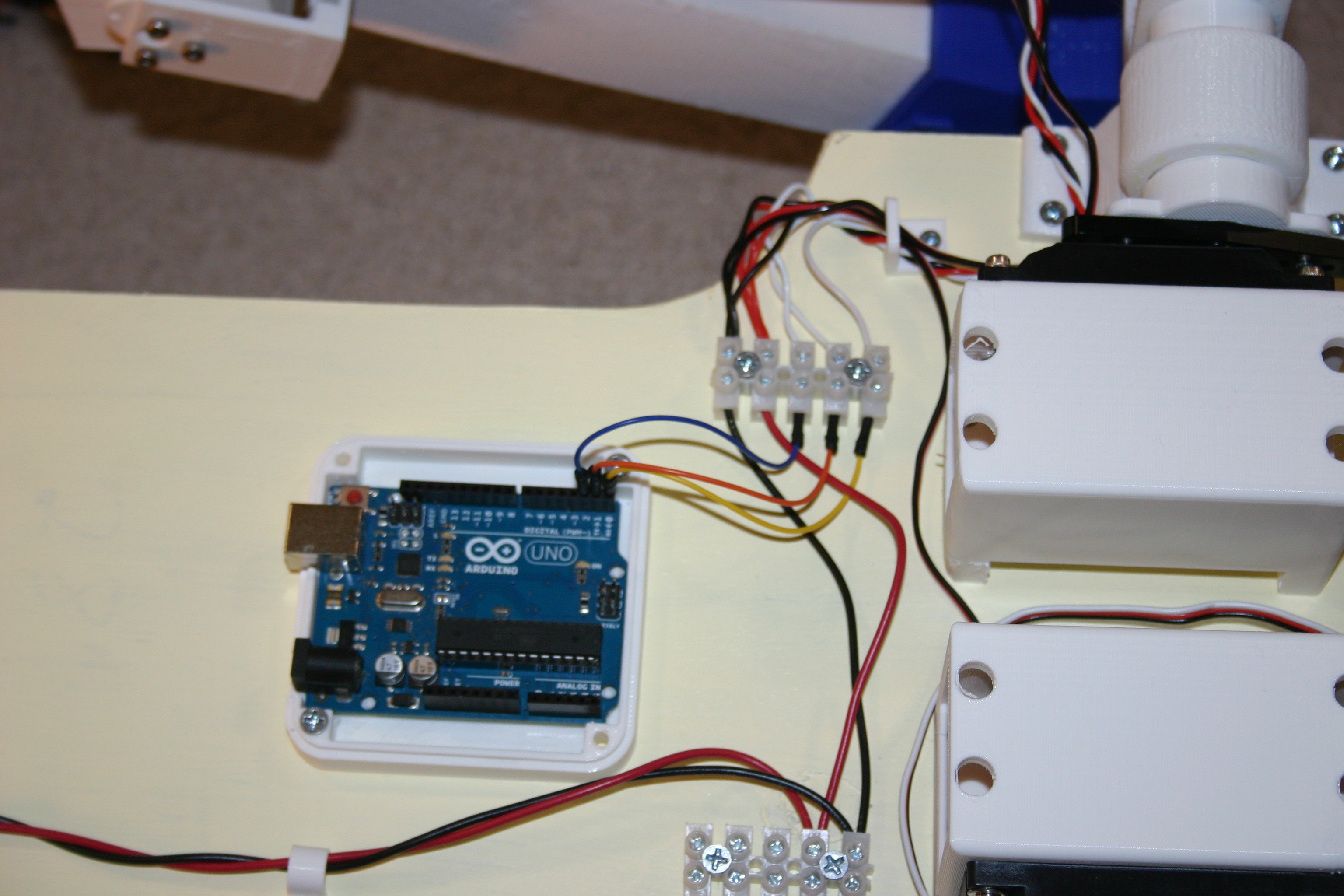
I added an Arduino Uno to control the servo motors.
![]()
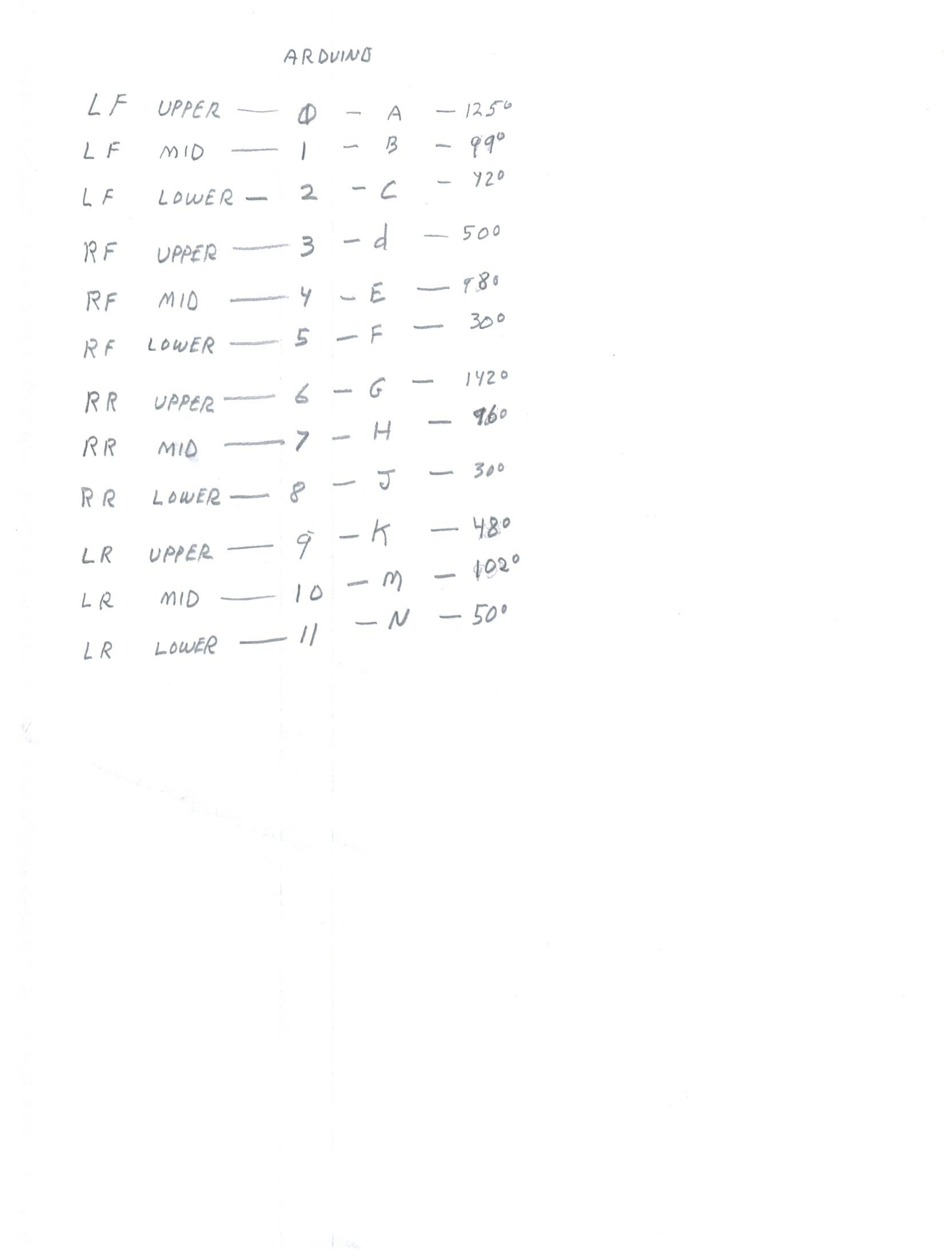
Pins 0 through 11 are connected as follows:
![]()
![]()
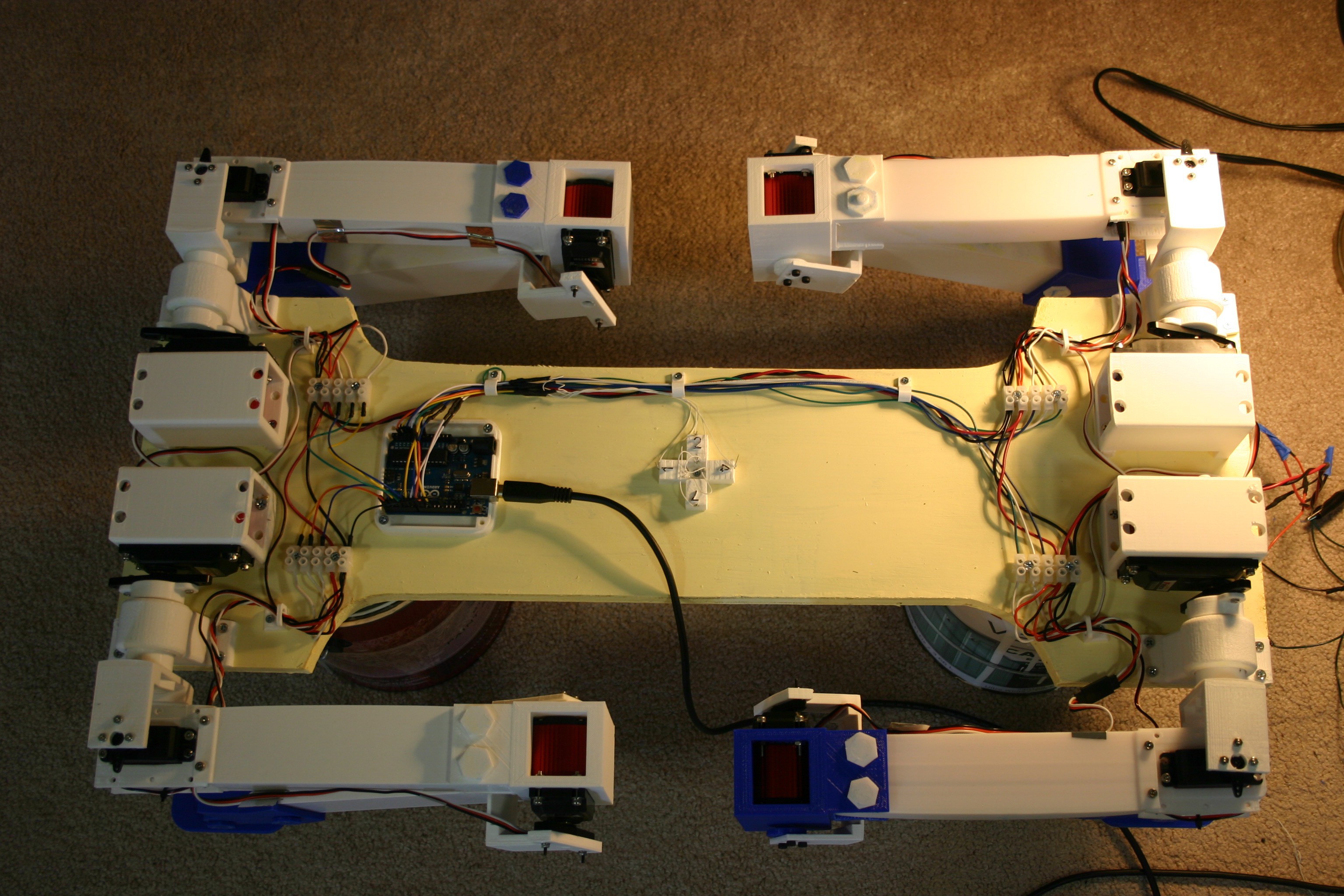
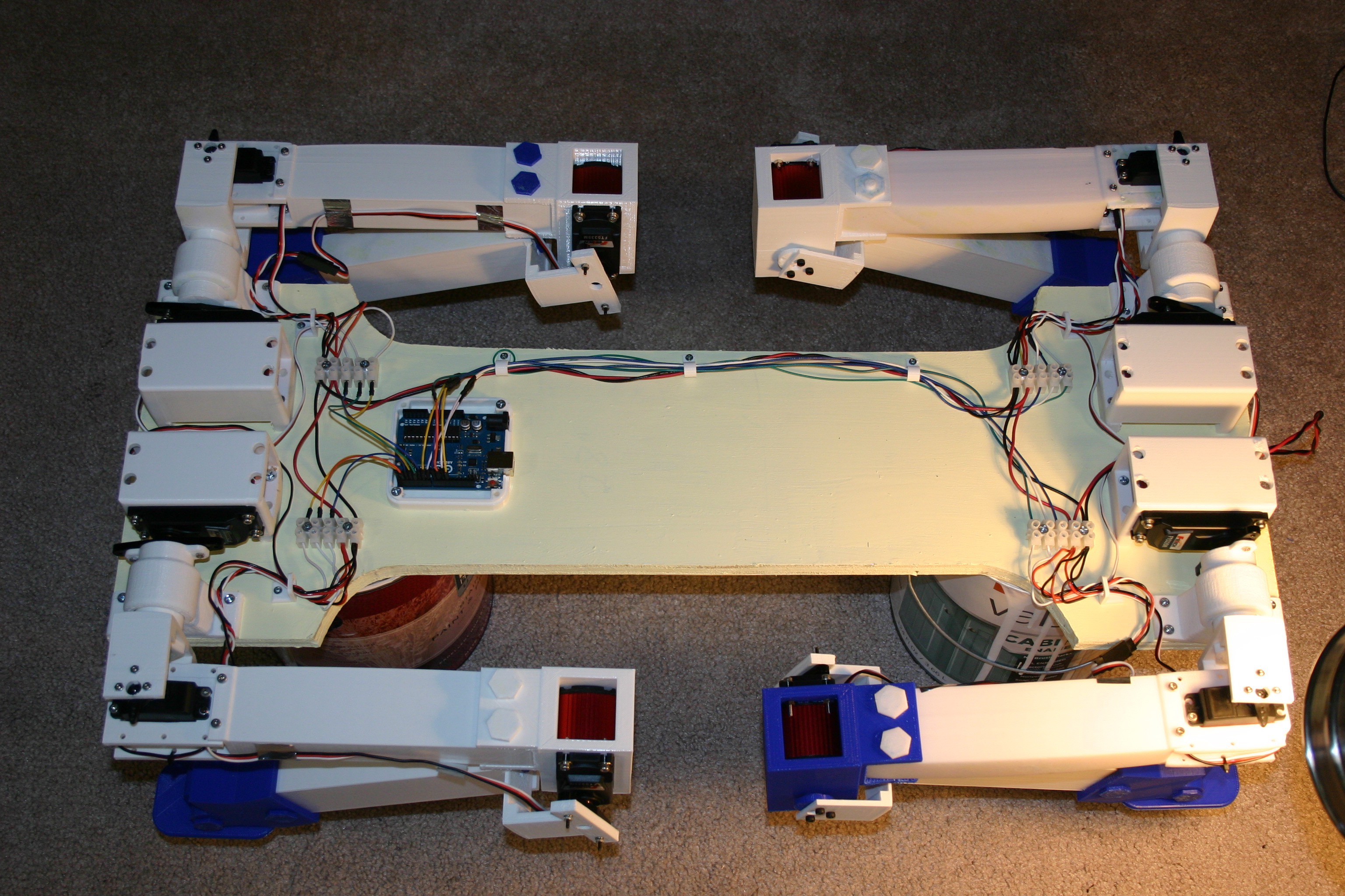
A top view of the connected wiring is shown below.
![]()
The starting position for the servo motors on the legs is shown below.
![]()
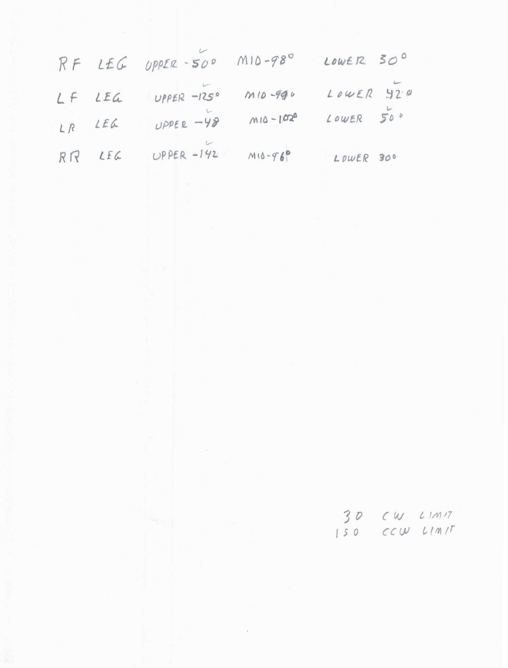
Because each spline on a servo shaft/horn represents about 15 degrees, the servo motors must be operated until a satisfactory position is achieved and that value should be recorded.
The .ino Arduino sketch for standing/sitting on this site as module test 0524.
Here's the standing routine.
-
Leg Test With High Torque Servo Motors
05/11/2018 at 19:42 • 0 commentsToday I tested the more powerful leg.
The original leg--using 20 kg-cm servos--could exert 1250 grams of "push" on a scale. The new leg--using 40 kg-cm servos--measured 3300 grams of "push" before the upper plywood test jig lifted. In other words, I'm getting nearly three times the lift with the new motors. The original leg used three $18. motors while the new leg uses one $18. motor and two $38. motors; so my cost per leg just went up $40.
The extra torque was too much for the upper axle piece and it sheared at the connection where it holds the leg.
![]()
I reprinted the axle at 100% fill and it is now holding for test purposes. I'm in the process of redesigning the connection for more strength.
An unexpected benefit of the new motors involves a stiff gear train that resists external movement. If I raise the leg in the air and remove power to the servo motors, the leg stays in place.
![]()
This is a major benefit in that the motors draw virtually no current (thus no wasted heat and battery energy) unless they are moving.
I'm working on stronger connections and I've ordered enough parts to complete four legs.
-
Google AIY Vision
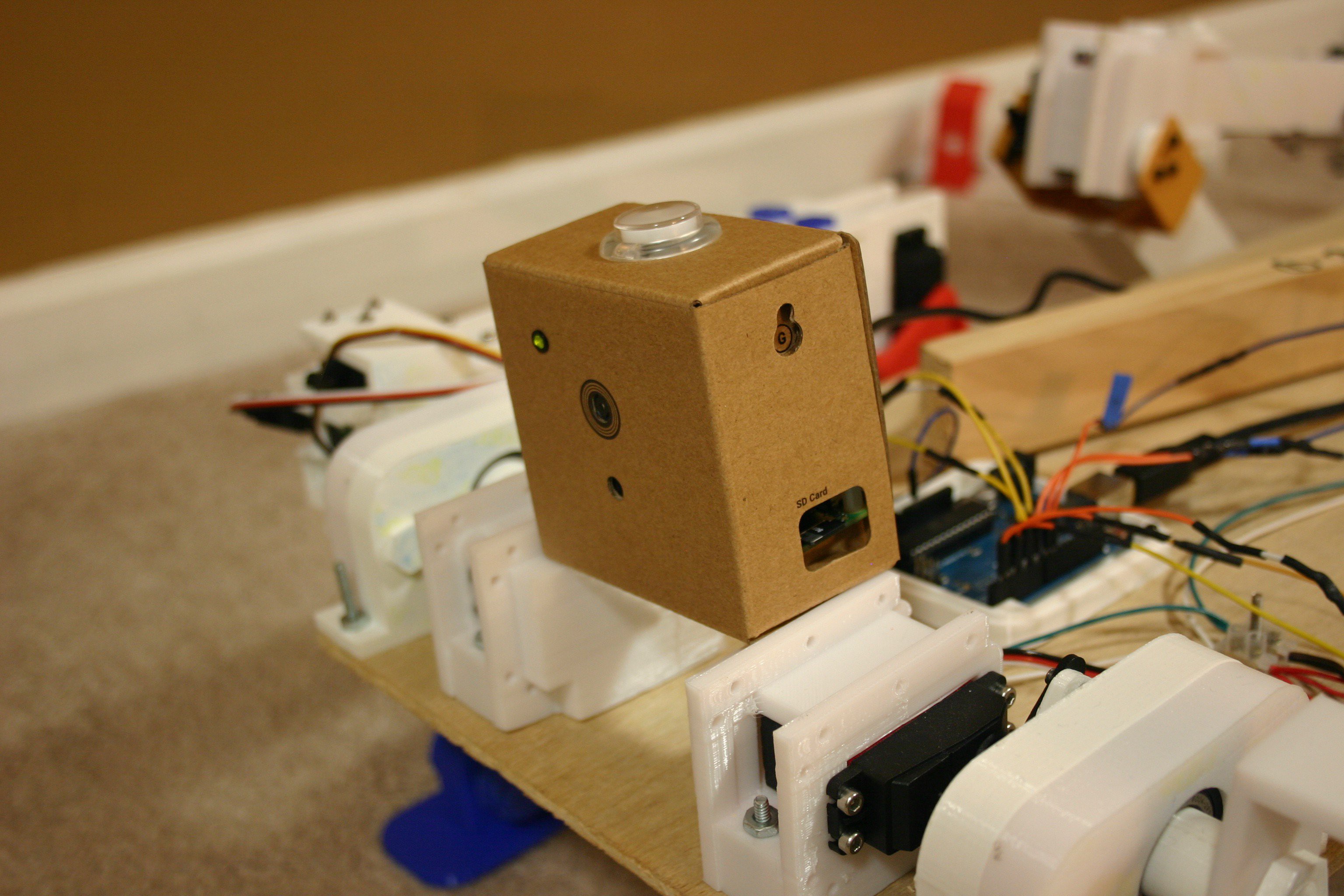
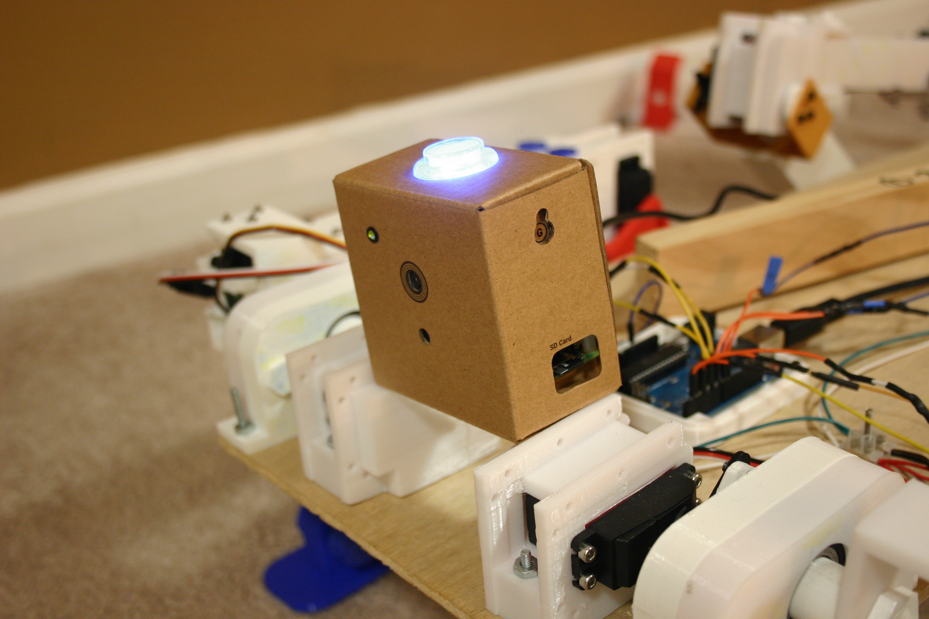
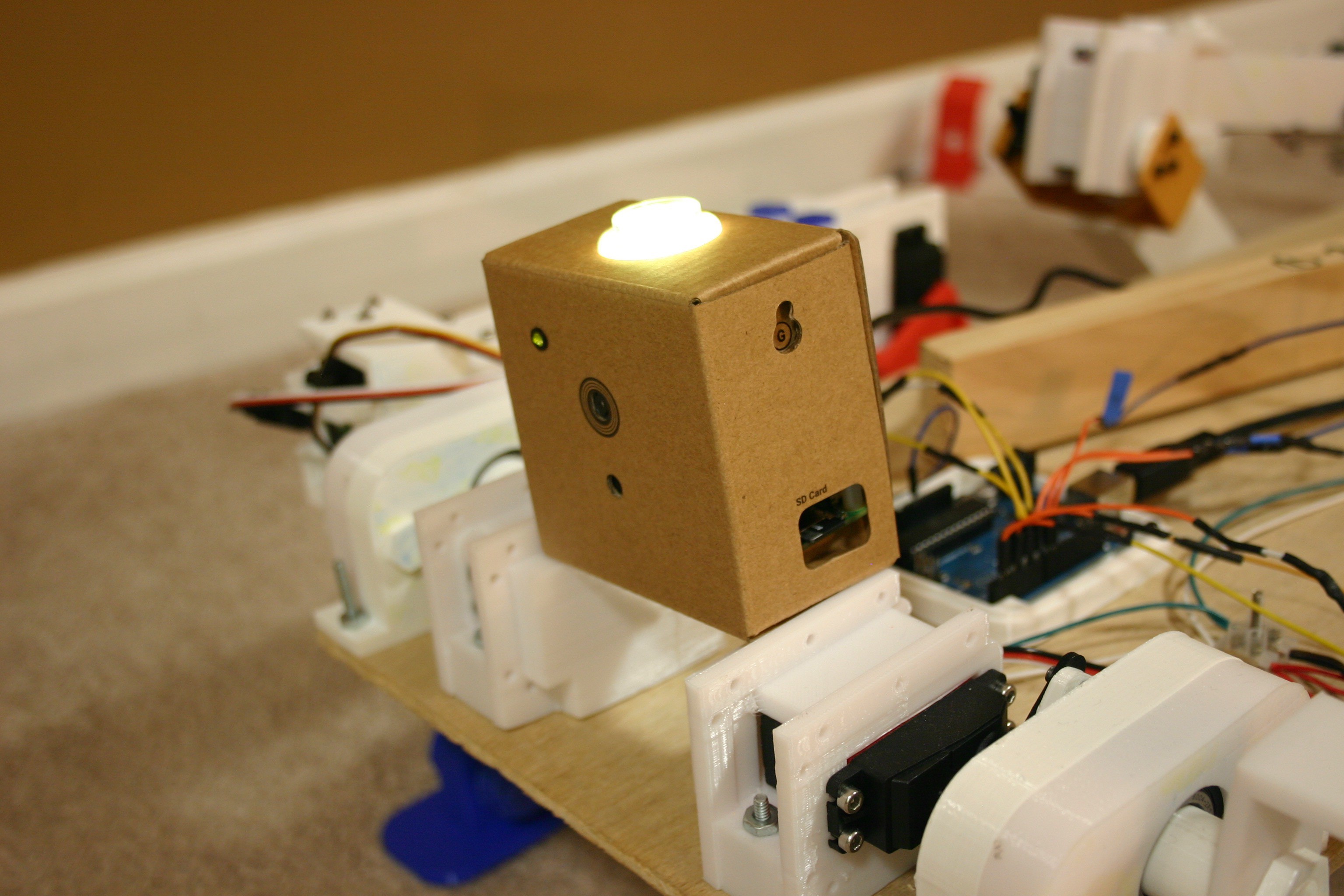
04/22/2018 at 00:27 • 0 commentsI assembled a Google AIY Vision Kit tonight (took about two hours). This will be great for the dog since it will allow the detection of humans and whether they are smiling. I am using the default mode--have not explored the many options at this time.
When no face is detected, the light on top is not illuminated.
![]()
When a face is detected (and it will easily detect a single face at a distance of 20 feet) the light turns blue.
![]()
When there is a smile, the light turns yellow. A big smile will turn the light bright yellow and trigger a piezo buzzer.
![]()
-
Stronger Leg
04/21/2018 at 18:59 • 0 commentsI've completed the addition of two larger, more powerful motors (twice the torque of the original servo motors). The files for the changed parts are available on this site.
![]()
First, I added the aluminum servo horn to the new shoulder axle.
![]()
Next, I disconnected the existing elbow joint.
![]()
Now, I set the new motor and bracket in a similar position to the old--so I wouldn't mix things up too much.
![]()
I mounted the motor to the upper leg.
![]()
I attached the aluminum servo horn and back bearing to the ankle servo connector.
![]()
I attached this assembly to the lower leg.
![]()
I attached the lower leg to the elbow assembly.
![]()
I pushed the shoulder axle through the linear bearing and attached it to the upper leg motor bracket.
![]()
I attached the servo horn to the servo motor and tightened the locking screw through the hole in the axle/shaft.
![]()
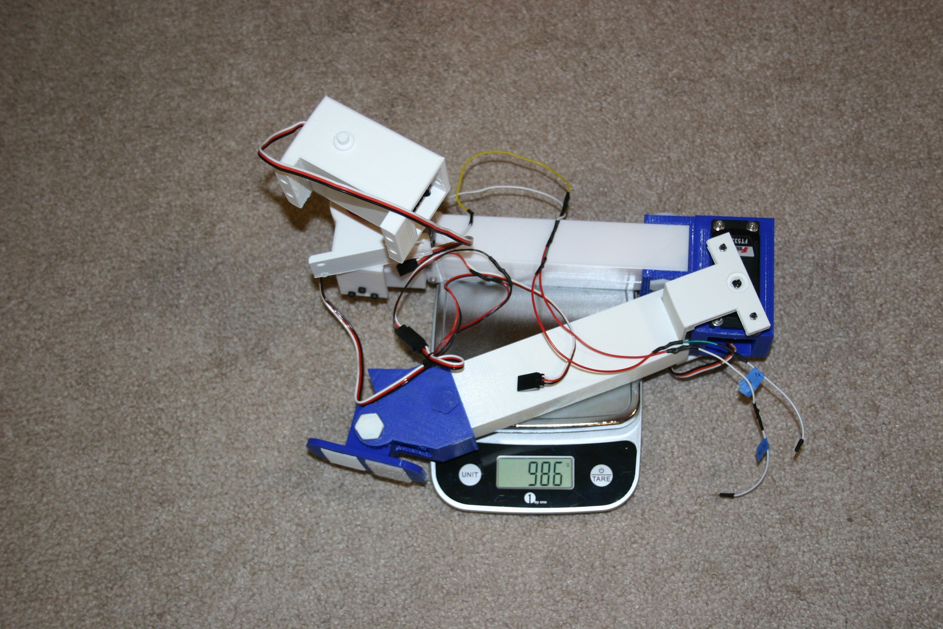
I checked the total leg mass and it came in at 986 grams--which is 86 grams more than the original.
![]()
-
Leg Removal and Upgrade--Part 1
04/14/2018 at 00:11 • 0 commentsThe left rear leg has to come off for new motors (twice the torque) in the shoulder and elbow joints. First, the wires have to be disconnected.
![]()
Next, the leg is removed from the body.
![]()
The total leg assembly will require design tweaking to keep the weight down and minimize some sharp edges (I don't want to get hurt--the motors are getting pretty powerful now). A good leg assembly could be a "module" for the Robotics Module Challenge.
![]()
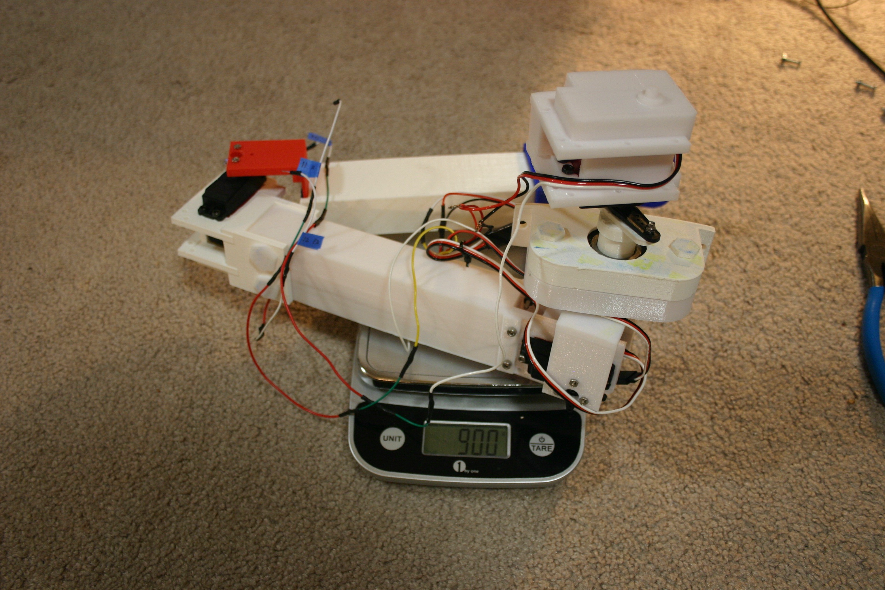
I put the existing leg assembly on the scales and it came in at 900 grams.
![]()
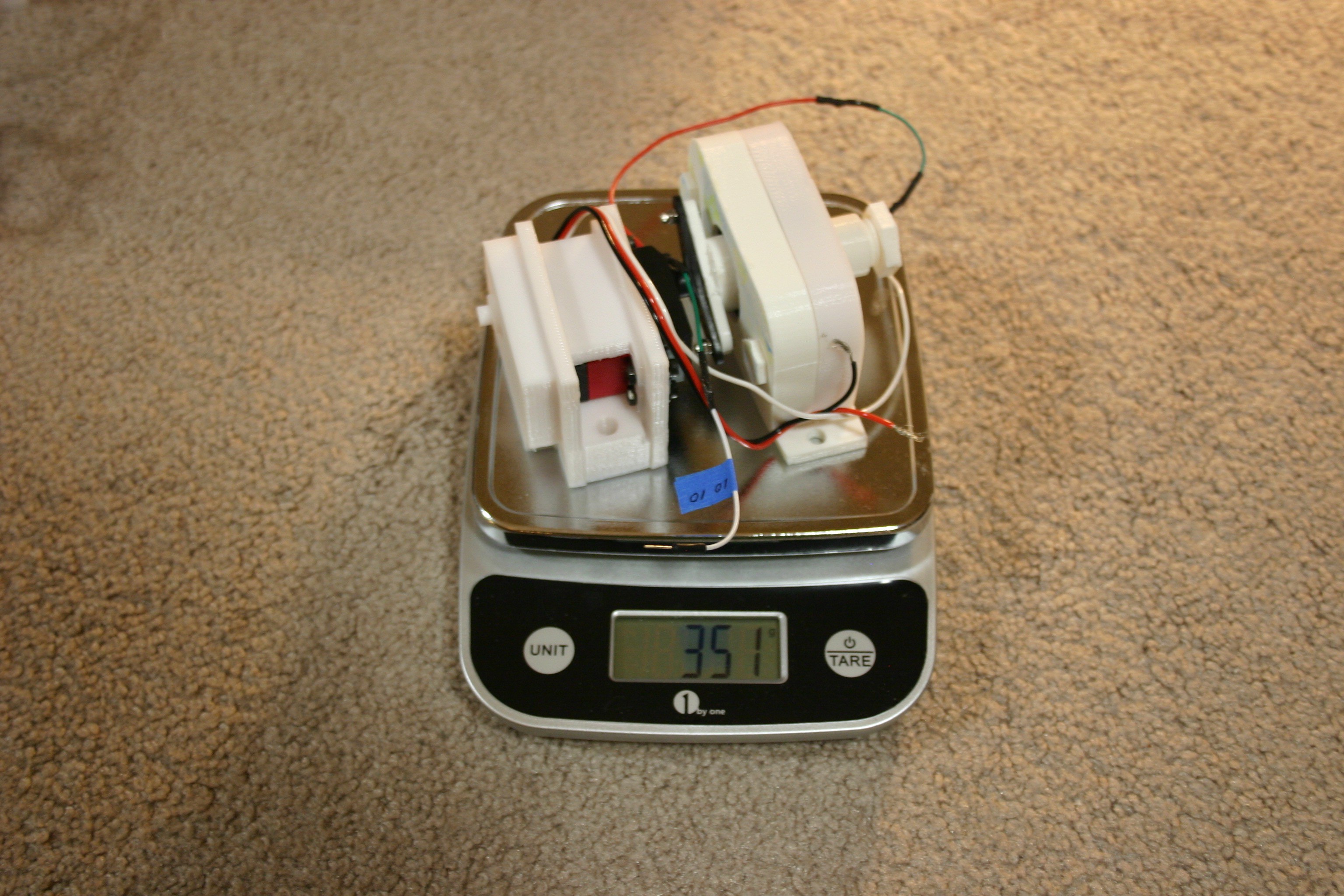
The shoulder motor and bearings (existing) are 351 grams.
![]()
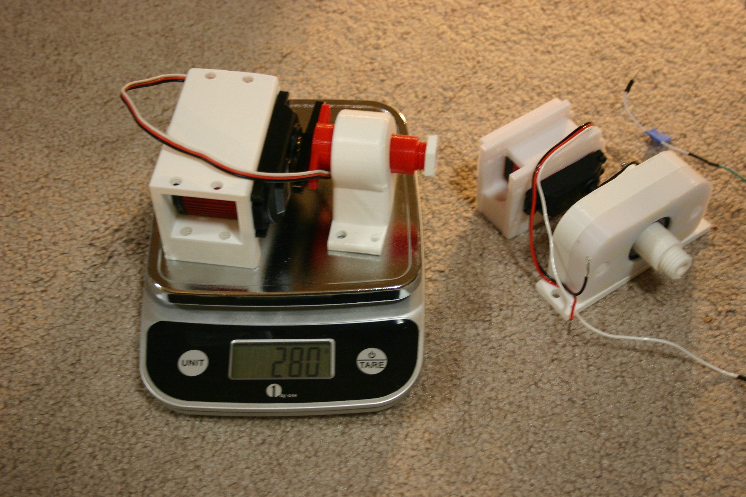
The new (larger and heavier motor) shoulder motor and printed bearing comes in at 280 grams.
![]()
At least it's going in the right direction--I would love to have the new leg weigh the same or less as the old leg.
Mike's Robot Dog
Boston Dynamics' robot dog, Spot Mini is unavailable at any price. A Chinese copy is $30,000. Cut 99% of the cost and build one at home.
 Mike Rigsby