Close
0%
0%

Soldering Iron Ring Light

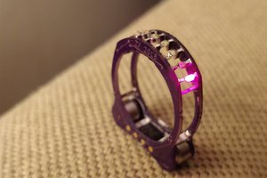
Light integrated into soldering iron to illuminate what I'm soldering, and learn a bit about SMD design and getting PCBs made

Similar projects worth following
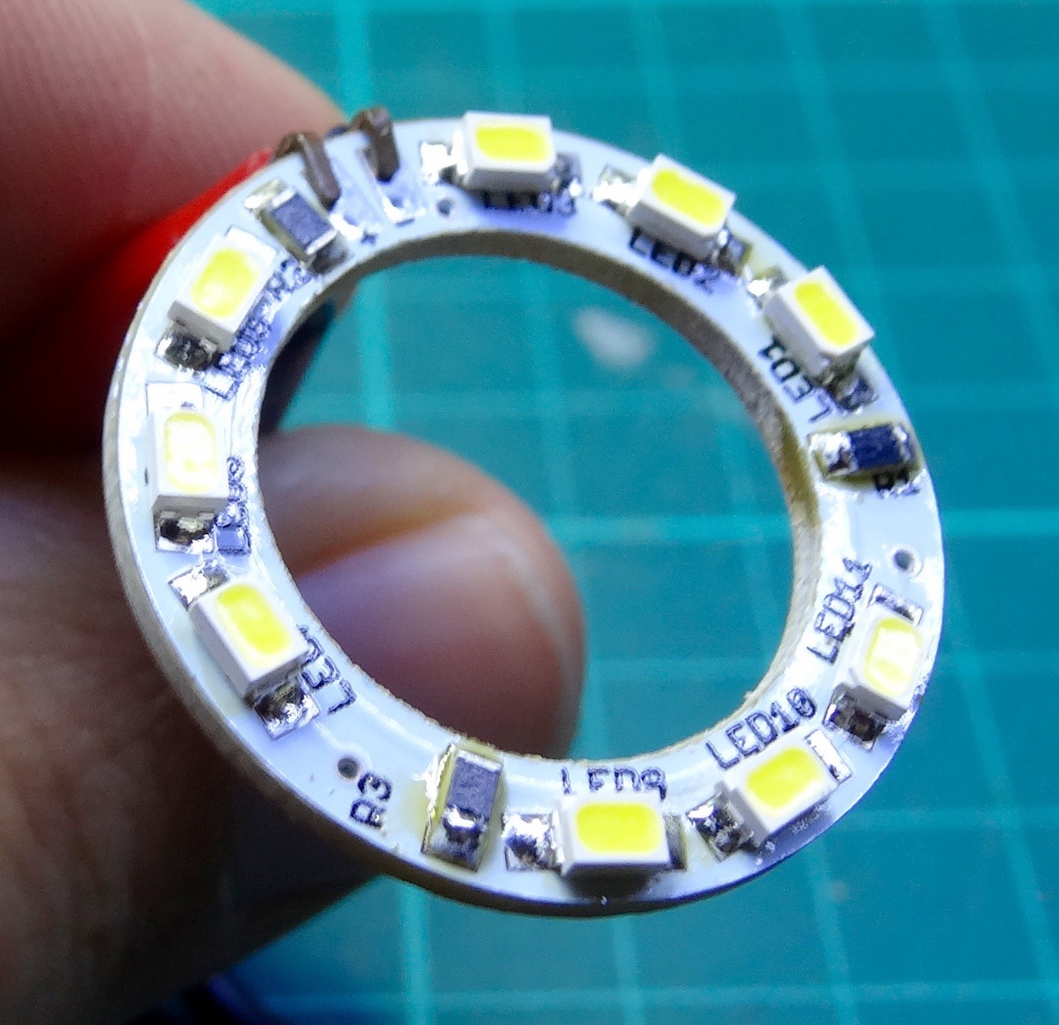
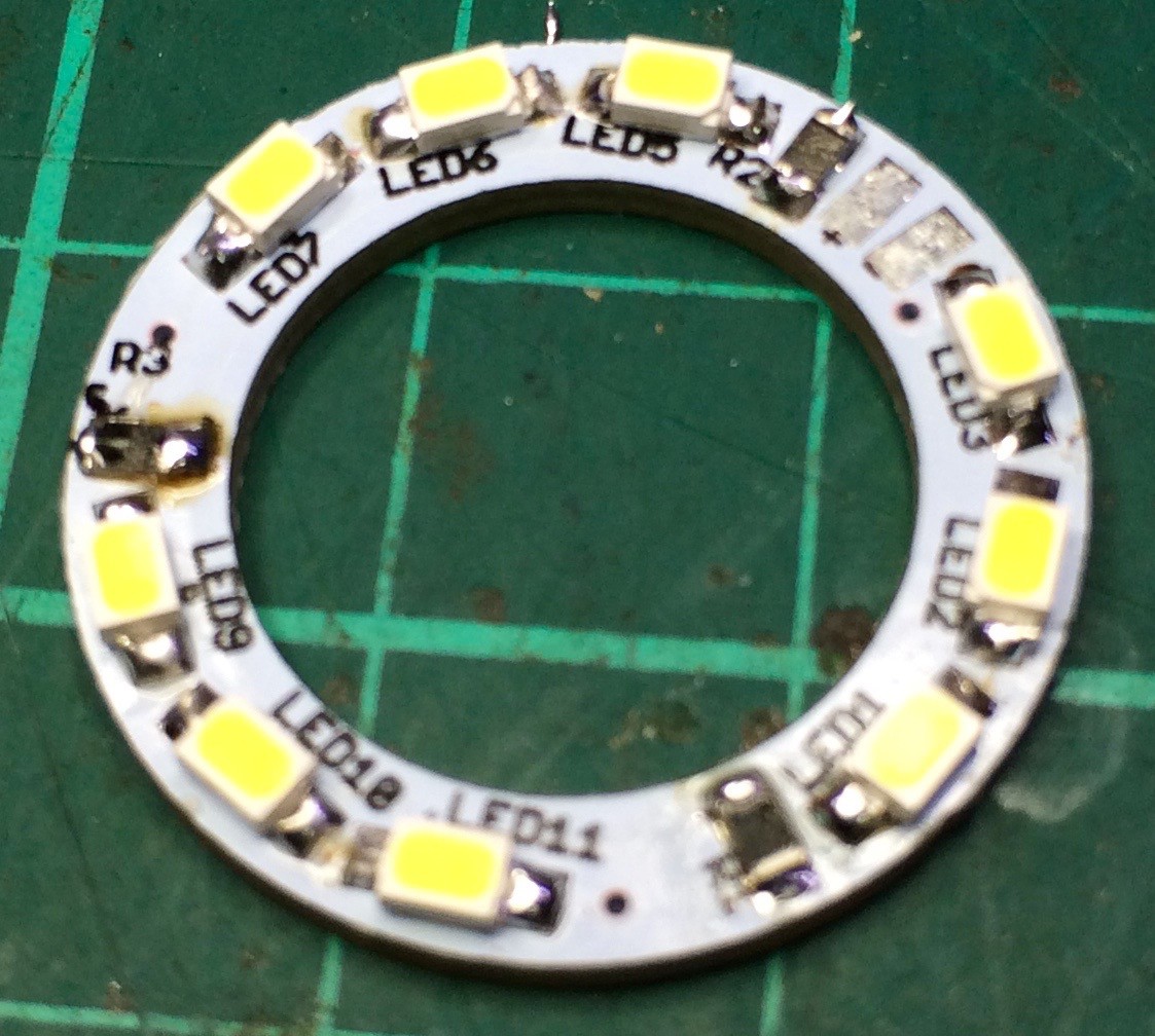
A simple little circuit board based on some SMD LEDs and resistors, and using a custom PCB I had made which fits onto my soldering iron.

This project is largely a way for me to ease into SMD design and assembly. I'm moving to SMD for some of my other projects (#Insulin Minder MK2, others) which would use custom PCBs and SMD components. Will be trying a few things here to see what works well (milling a PCM at home, getting one made by a PCB service, hand-soldering SMD components, solder paste + hot air rework). No ICs in this one, but its a start. Plus will hopefully end up with a useful add-on for my soldering iron.

  • 9 × Cree PLCC-2 cool white surface mount LED [CLM3C-WKW-CWBYA453] From LEDSales.com.au, 1400 to 3500mcd at 20mA. Colour temp is typically 5500K.
  • 3 × 120 ohm 0805 SMD resistor Discrete Semiconductors / Thyristors (DIACs, SIDACs, TRIACs, SCRs)

  • ​Skillet Method

    Linus Dillon05/21/2015 at 11:17 0 comments

    Well, gave the skillet method a try. For those unfamiliar: https://www.sparkfun.com/tutorials/59.

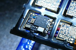
    Basically, I put solder paste (lead free in this case) down on each of the SMD pads using the syringe, placed all the SMD components, popped it all onto a frying pan (old one), and heated it on the stove until the solder paste reflowed. From beginning to end it took maybe 15 minutes, so certainly fast. I'd have to say probably easier than the half soldering even, and the result are slightly better I think. The reflow took much less time than I expected; maybe 2 to 5 minutes at most from cold to reflow.

    And it all works as expected still. I think this is the method I'll be using for most SMD work going forward; not when I have only a couple of basic components, but whenever I have a lot or multi-lead ICs and such. For those who might knock me for not hand soldering everything, this is the method I'm comfortable with; your mileage may vary.

  • Solder Paste + Hot Air Rework

    Linus Dillon04/30/2015 at 11:06 0 comments

    I've now had a go at using some solder paste and heating it to the required temperature using hot air.

    Turned out fairly neat. I did have trouble working out what temperature worked though. The resister was done with air at full blast and it almost got blown off the board. I dialled it down on the LEDs, but they then seemed to have trouble reflowing the paste, even at 350℃ (must check how hot it REALLY is though).

    I might try the skillet method next. I think that may give the best and easiest results for SMD ICs.

  • Assembly

    Linus Dillon04/25/2015 at 02:10 0 comments

    An now assembly. First try is by simply hand soldering the parts. The technique I'd read was to put a small blob/dome of solder on one pad, then hold the component in place and melt it again to tack the part down, then go round and solder the remaining pins (possibly just by applying a blob of sold to the iron and letting this flow into place by touching the iron to the component/pad).

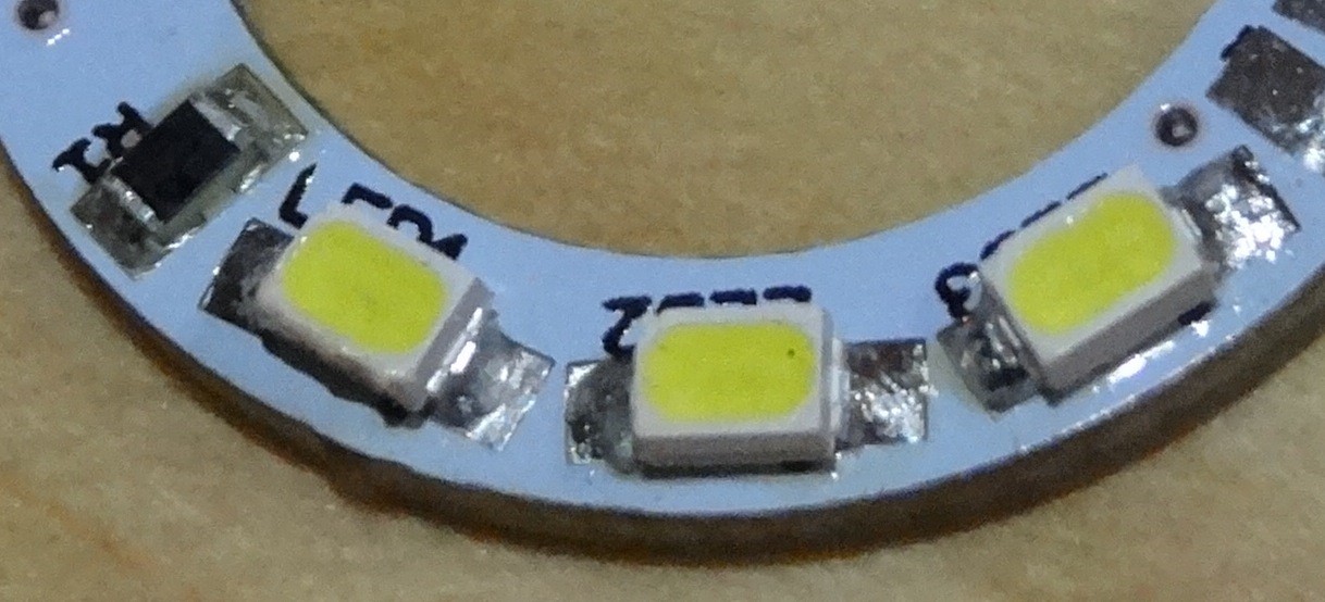
    Was a little interesting identifying the polarity of the LEDs; they have a tiny little bite taken out of one corner to denote the anode, but its so small I had to use my magnifier to make sure I had it right. I ended up using the magnifier for all of it. I worked in thirds so I could test each segment of three once it was assembled. Resistor first (being the smallest) then its three corresponding LEDs. I had my iron set to 320C (have not checked to see how accurate this is). All went quite well, although I did have a little problem with solder forming a peak when I moved the soldering iron away. Reheating didn't help. Might try hitting it with my hot-air rework unit to see if I can neaten the joints up.

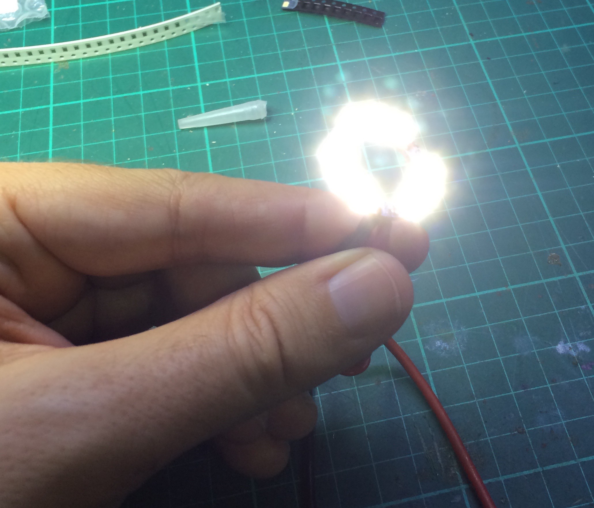
    Once done I soldered on some wires and it all works. A surprising amount of light actually.

    Now I just have to fit it to the iron and sort out a power supply for it. a 3D printed cowl might also be a good idea.

  • Professional Board

    Linus Dillon04/25/2015 at 01:56 0 comments

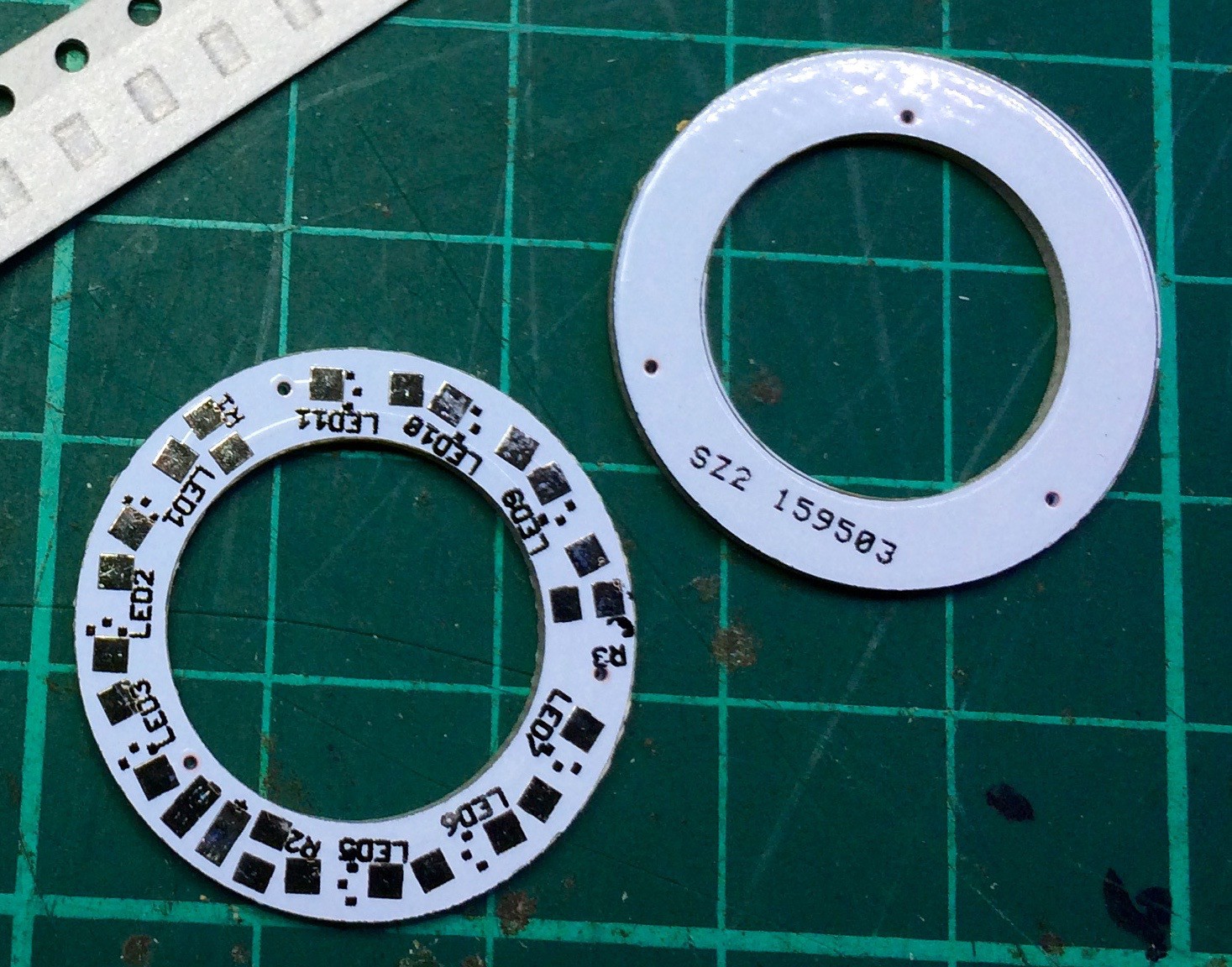
    I spent little time tweaking my EagleCAD design for sending off to a PCB maker (specifically running design rules check on it, and scaling/aligning the text for the silkscreen). I ended up using Seeed Studio, as I also wanted to order some parts. I sprung for bit extra and went with the white PCB - justified it thinking it would reflect the light better (but really it just looks neat). The reasons why I had not gone with this option initially were price and time; however prices seem to have come down since I last looked into this, and I had my boards after only 8 days. Frankly for the reduction in hassle and much improved result I think this is the way I'll go in the future.


  • Milled board

    Linus Dillon04/25/2015 at 01:50 0 comments

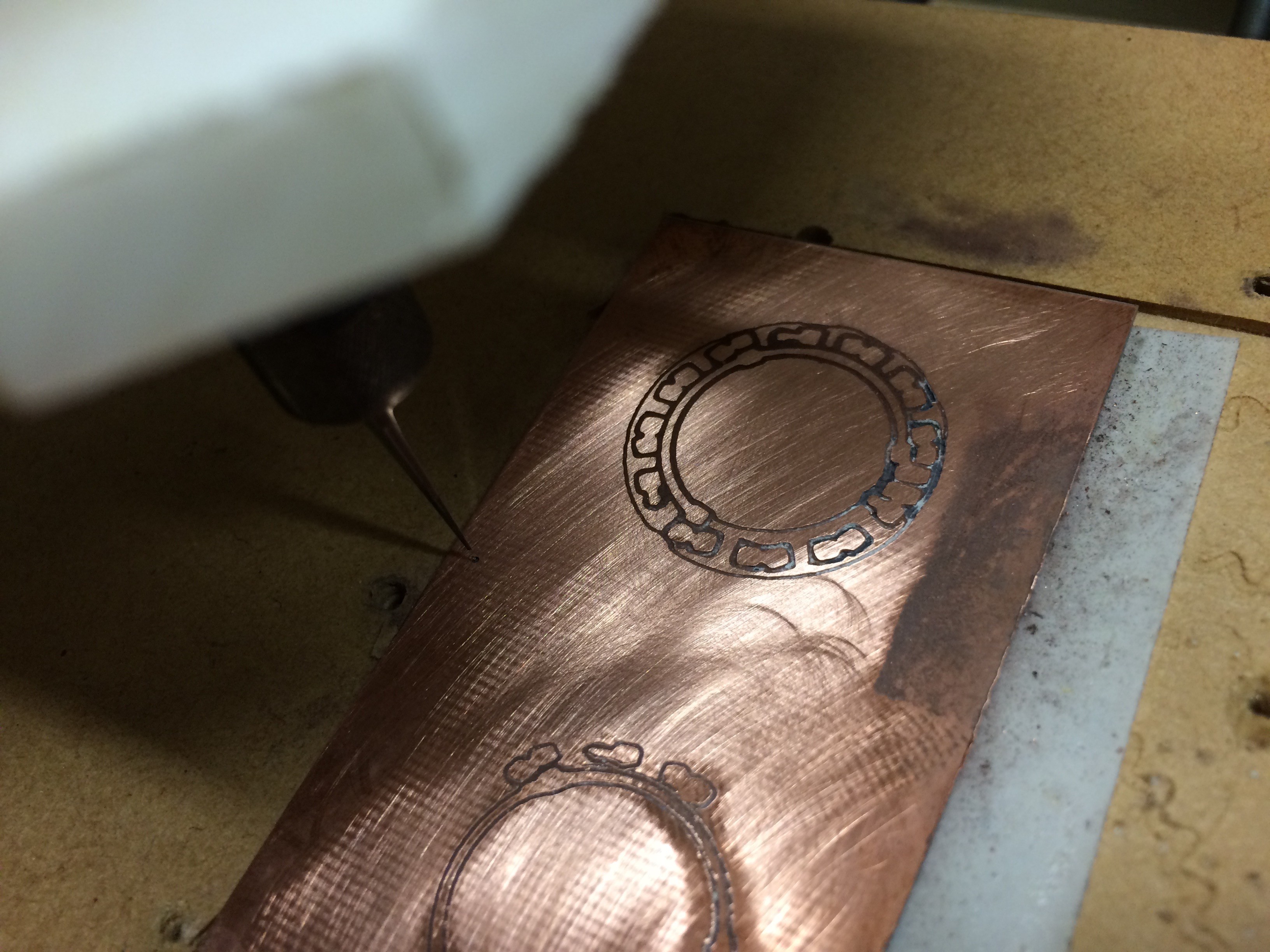
    My first try at this was to mill a PCB using my kit-build CNC machine. Now this is a VERY basic machine (from the original http://www.mydiycnc.com kickstarter) with a Dremel fitted to it. I have successfully milled a through-hole single sided board on it before, but it was close to being borderline. Anyway, I went through the same process this time (EagleCAD, exporting via the PCB plugin, then into EMC2). I did use a 10 degree v-bit this time rather than an end-mill hoping to get finer detail this time.


    I'm afraid however that it didn't go well. As you can see from the pictures, the milled lines tended to wander a bit - it looks like runout in the Dremel is the main issue, although there is also a small amount of play in the overall machine too. The first try was not quite deep enough to cleanly mill through the copper. I repositioned and tweaked the z-axis home and tried again, but this time it got only a short way before the v-bit tip broke! Clearly I'm doing something wrong (maybe dropping the milling speed would help?), OR this machine simply isn't up to this (+/- 1mm or more wobble at the bit could doom it entirely).

    Anyway, onto plan B: getting it professionally made.

View all 5 project logs

Enjoy this project?

Share

Discussions

willemstaal wrote 09/04/2015 at 13:14 point

This could be a cheap ringlight for a pocket camera too! 

  Are you sure? yes | no

Similar Projects

Does this project spark your interest?

Become a member to follow this project and never miss any updates