Close
0%
0%

Sub $200 PCB Mill that doesn't suck!

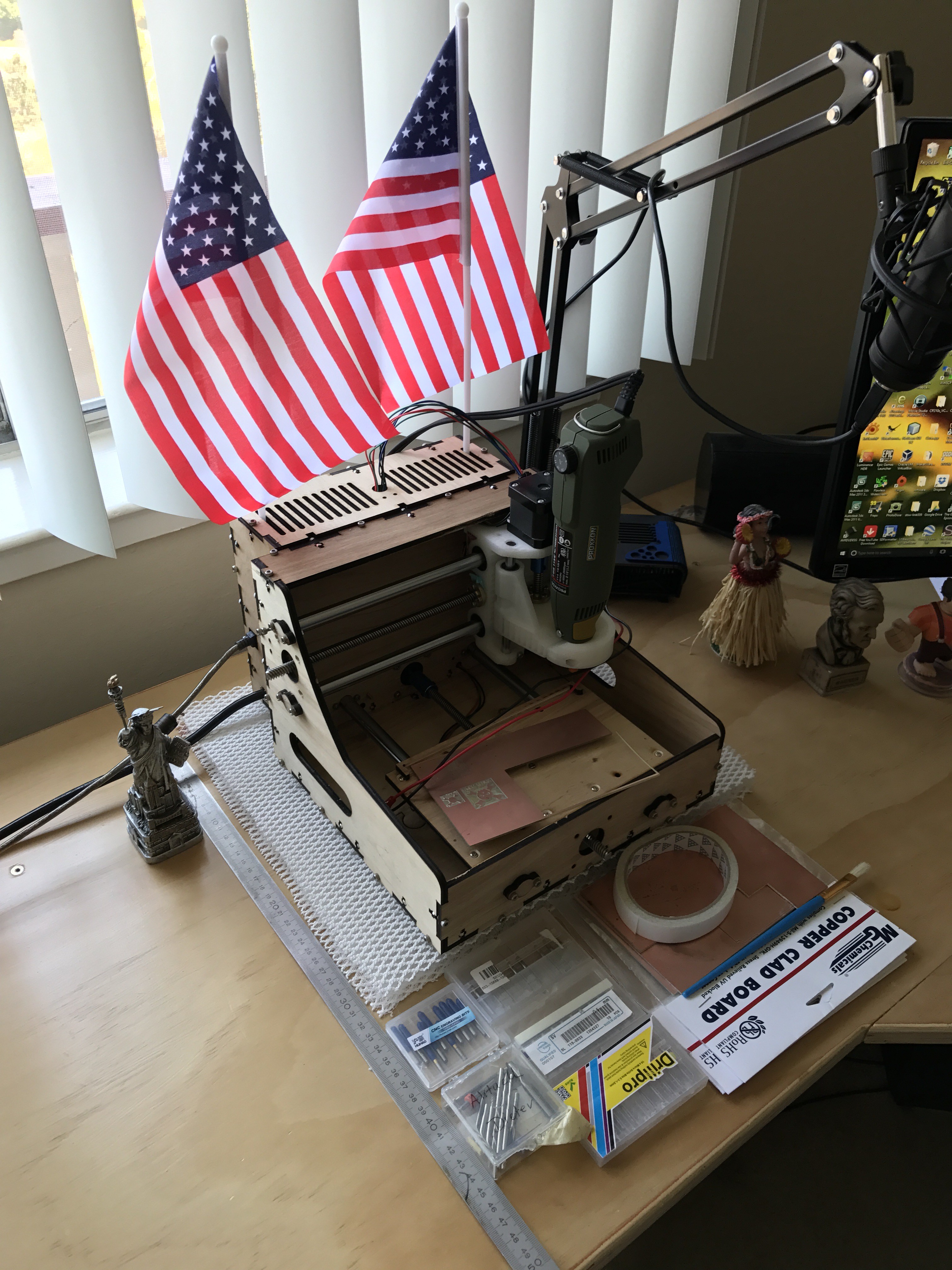
A PCB mill inspired by open source CNC 3D printers with a custom design to fit standard size copper clad boards (6" x 4" / 160mm x 100mm)

Similar projects worth following
A 3D Printer inspired CNC mill specifically designed to work with 160mm x 100mm (European Standard Format) or 6" x 4" as obtainable everywhere in the US.

Main Features:
- < $200 in material (excluding Multitool and mill bits)
- Etching of single as well as double sided PCBs
- Milling of random PCB outlines
- Drilling of all holes (> 0.5mm)
- Automatic homing
- Automatic Z-Leveling using probing in CNCGcodeController
- Precise enough for 8 mill traces
- Compatible to Eagle, PCB-Gcode, CncGcodeController, grblController
- Knobs for manually adjusting the position
- Only three 3D printed parts designed for PLA and to not warp
- Easy to lasercut on cheap Chinese K40 CO2 laser at home using 5mm plywood from the local hardware store (or in high quality aluminium on an industrial laser cutter)
- Very easy to assemble and to use
- Relay and wall plug for switching the Multitool on and off using G-Code
- Easy to transport and to set up
- No overly exposed wirin

Part List:

It would be good to have access to a laser cutter to make this. Otherwise just order the parts including material from your local laser cutting shop.

Print Instructions:

I use KisSlicer for printing my parts! I use it because it offers a VERY valuable function which calculates insets for holes. Properly calibrated, this gives me exactly 12mm when I design a 12mm hole! For all parts, this means that I can pressfit my linear bushings! Please keep that in mind before you kick of your 10h prints!

GPX Converter.rar

Tool to convert gCode to Makerbot binary format. Needs proper configuration in param.ini DISCLAIMER: I have only tested this on my Malyan M180 and have no idea if it works with Makerbot at all.

RAR Archive - 134.99 kB - 12/12/2017 at 03:40

Download

X-Axis.IGS

IGS file for 3D printed part so that you can modify it to your desire.

Initial Graphics Exchange Specification (IGES) - 2.82 MB - 12/12/2017 at 03:37

Download

Z-Axis UpperRodHolder.IGS

IGS file for 3D printed part so that you can modify it to your desire.

Initial Graphics Exchange Specification (IGES) - 2.24 MB - 12/12/2017 at 03:37

Download

Z-Axis RunCat.IGS

IGS file for 3D printed part so that you can modify it to your desire.

Initial Graphics Exchange Specification (IGES) - 1.66 MB - 12/12/2017 at 03:37

Download

NuggetMill5 - step.rar

Complete NuggetMill5 as a step file.

RAR Archive - 1.51 MB - 07/14/2017 at 01:43

Download

View all 8 files

  • Let's talk cost - time, rather

    Timo Birnschein01/15/2022 at 15:08 0 comments

    I want to take a moment and discuss what it means to make boards at home.

    At first glance, it seems like a great idea and it certainly was when I started making boards at home. You get the parts quickly, at least that's the thought, and you can find bugs before you make a larger run with a board house if needed.

    As far as prototyping goes, that's the end of it. However, the actual process of making a board on a home made or cheap CNC machine is very involved and can cost tens of hours - per board. I'll go into a little more detail why this is such a crazy high number in a bit. Today, you can just go to a company like jlcpcb.com and get your board made in a day and shipped in three if you are willing to pay $15 for shipping for your $2 PCB. But you get it in the color you want within a week, no questions asked. That's amazing and in my experience, these boards come out great! If you are willing to wait for the cheap shipping, it'll take about two to three weeks for your boards to arrive, which - given that I'll talk more about the tens of hours - still doesn't sound too bad.

    What it takes...

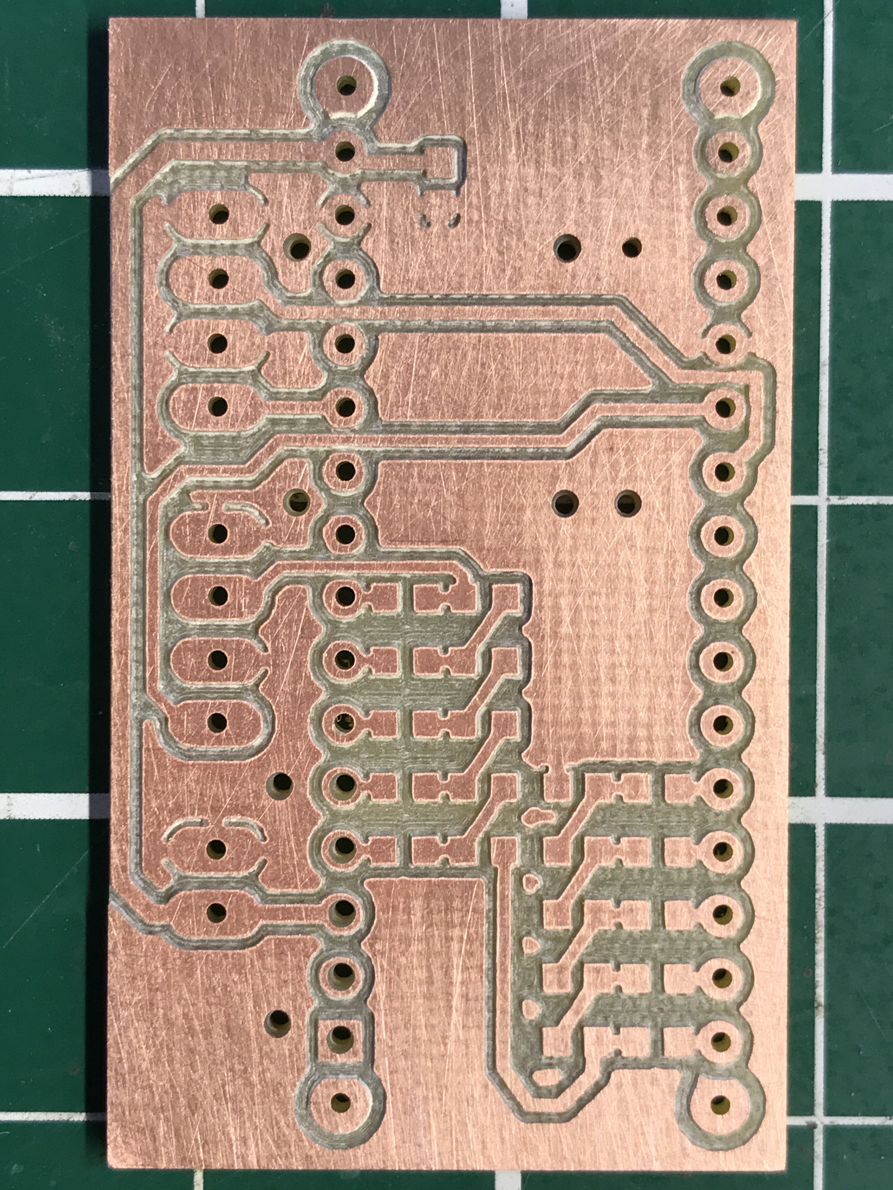
    1. First of, it takes longer to design a double sided PCB for home manufacturing.
      It does, because vias and traces need to be larger and thicker than they would for a manufactured board. It easily translates one way (to the board house) but rarely the other (to the home cnc mill).
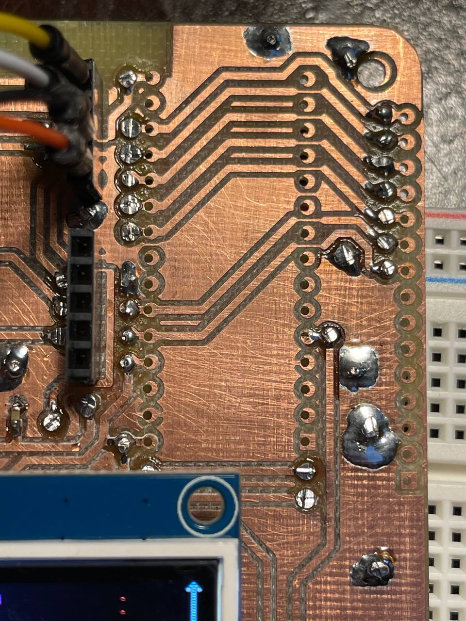
    2. Small vias with tiny holes are difficult to make at home simply because you have to manually solder top and bottom of the via with a snippet of wire or a very tiny rivet. If the hole is too small, that won't work. For that reason, my vias are 2mm in diameter with 0.8-0.9mm holes. That's huge compared to what I would do when designing for manufacturing.
    3. Since the regular home pcb workshop does not have the ability to galvanize boards at home and create the through-hole plating, all vias have to be hand solders or riveted AND none of the connections to pin headers can be connected from both sides! Because there is no through-hole plating! That means, all connection on my boards to any of the pin headers are exclusively connected on the bottom side of the PCB. Often, that means a lot of extra vias just to connect the trace at the bottom even though I have a trace right in front of the pin at the top - and there is usually no space for an additional, large via.
    4. Traces need to be thick to allow for error. I have managed to get my trace size down to 0.3 mm for short sections. Like for example when I need to get a trace in between two pins of 2.54mm pin-header. I go from 0.8mm down to 0.3mm, go through the two pins, and immediately go back to 0.8mm. I do that because I have seen traces break either after the milling was done or cut into pieces due to the last remaining play and backlash in the system. Bigger traces need larger spaces.
    5. The same is true for the space in between traces and vias, called clearance. My clearance in the design rule checks is set to 0.26mm as that's the setting in FlatCAM for my router bit. If I go with a lower clearance, I run into shorts because the traces aren't separated after milling.
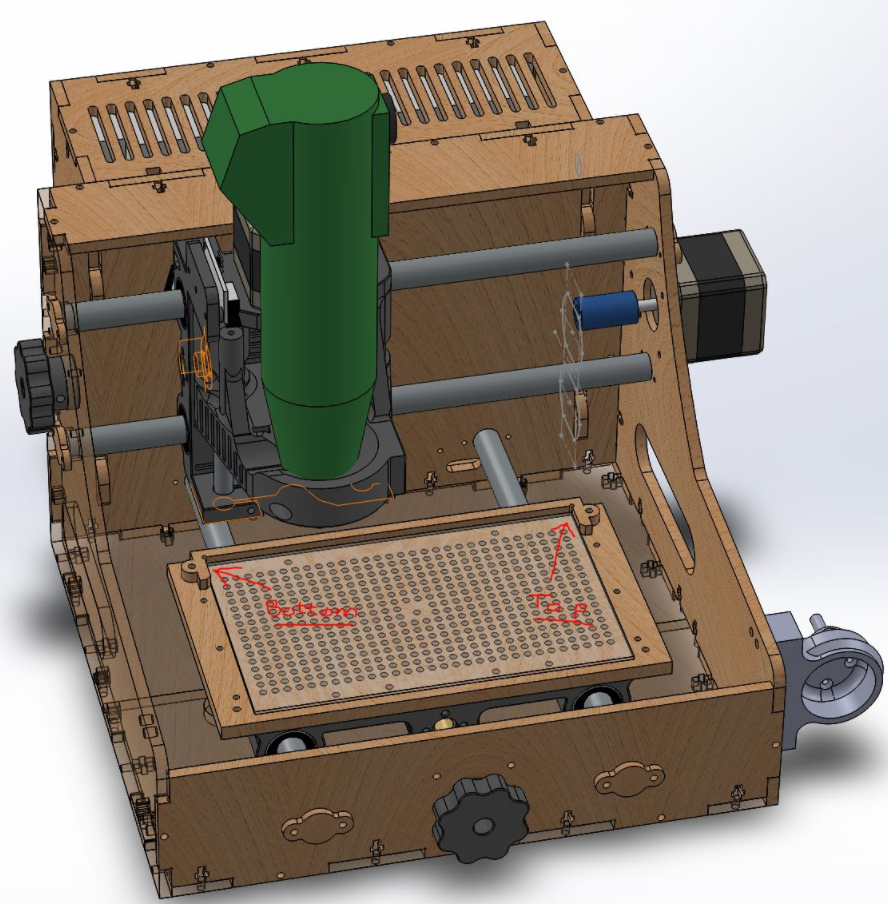
    6. Double sided PCBs must be aligned perfectly on the cnc mill. The slightest misalignment has the potential to destroy precious vias and pin-header connections. I had multiple instances where a skew in my machine caused traces to break that use a through-hole of a pin header to go from one side of the pin header to the other, on the same side of the PCB. This happens because I mill the top side first, then flip the PCB over to mill the bottom side and then drill the holes on the bottom side. If the PCB is not aligned perfectly, the drilled holes look great on the bottom side but are offset on the top side -> disaster as this cuts the rest-ring in half cutting the connection.
    7.  My personal machine has a small skew. That's because the machine was lasercut on my cheap laser cutter. It's minor but it's there. Aligning top and bottom side perfectly is therefore...
    Read more »

  • Adding a vacuum table - the best upgrade!

    Timo Birnschein01/14/2022 at 23:04 3 comments

    There are upgrades and there are upgrades.

    Sometimes, an upgrade is a small thing. An LED here, a new line of code that improves things there... this is a major major livability improvement that I wasn't expecting to work this well:

    I added a vacuum table to my mill. It's rather unbelievable that not every PCB mill has one.

    The Issue:

    Boards aren't flat. They never are. The CNC bed isn't flat either. You can make it flat but that costs a lot of time and potentially frustration depending on the material of the bed. My bed is laser cut plywood and I can cut it on my laser cutter. The carrier is 3D printed and I can print it on my 3d printer.

    When placing a PCB onto the bed, it must be secured somehow such that it doesn't wonder off. Clamping it down might lead to warping since I press the material into the plywood, or worst, clamp it from the side. Then the PCB can be a bit warped and despite my best efforts, I was never able to get it 100% flat without spending 30 minutes on pushing and bending and rolling the PCB until I couldn't see and flex anymore when pressing onto the board with my finger. An insane piece of work that, if not done absolutely right, can ruin an hour long cnc job.

    The Solution:

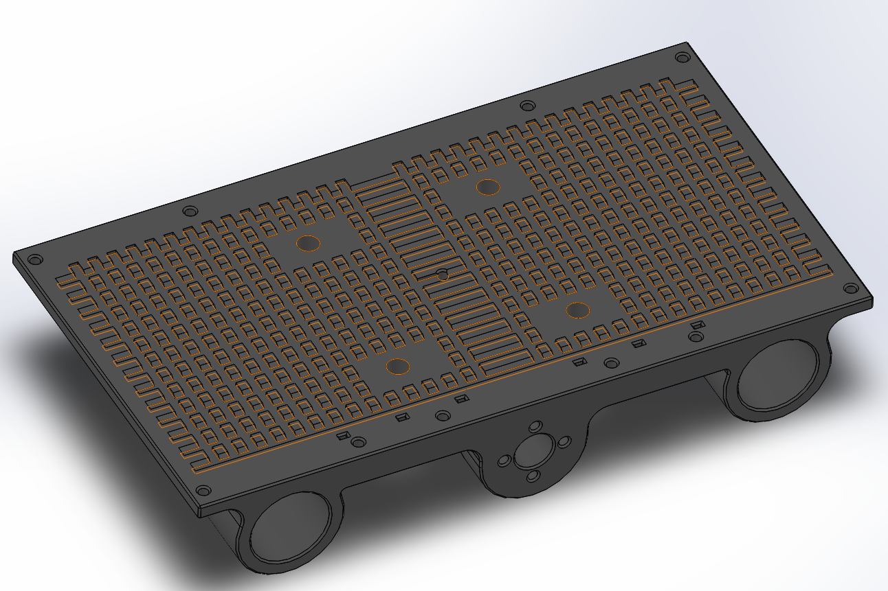
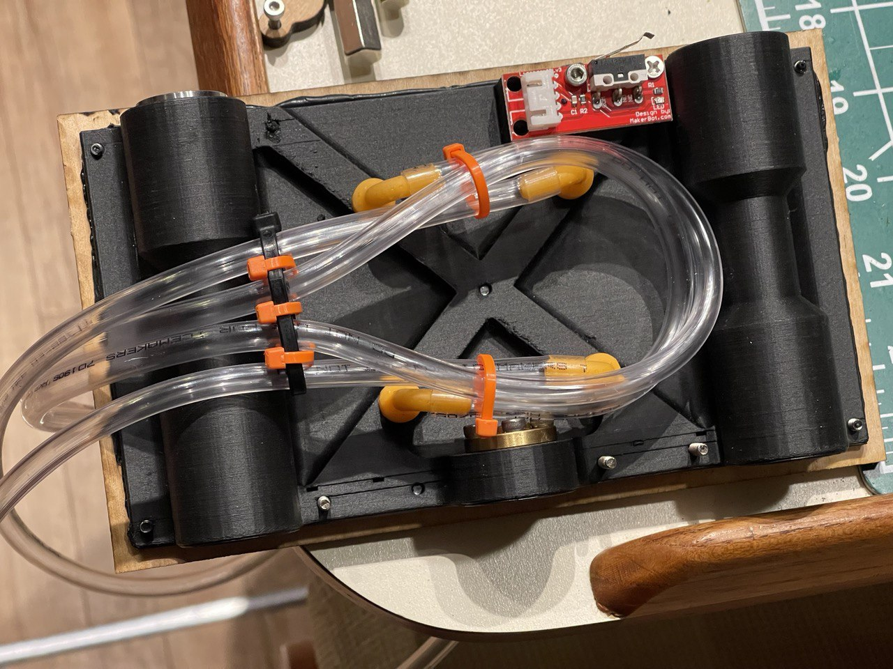
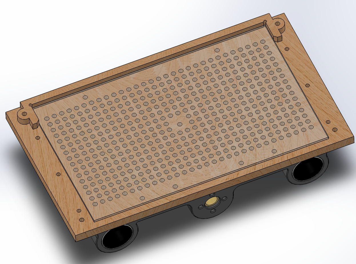
    In the original version of the bed, I already had ribs to avoid warping during the print and to make the part a bit stronger since these ribs would add material to the perimeter. One night, I thought to myself: "Vacuum doesn't need much airflow, why not just make the ribs into tiny stand-offs and laser cut holes into the bed?" Well? Seriously, why not? All vacuum needs is a volume and a way to create suction, like using a vacuum cleaner. I have one that I never liked because the head is so ill-designed that it doesn't clean at all. However, when the hose is used by itself, it's remarkably powerful for a $50 part.

    One morning, I decided to get to work and redesign the X-axis carrier to allow sucking the air out from underneath the bed.

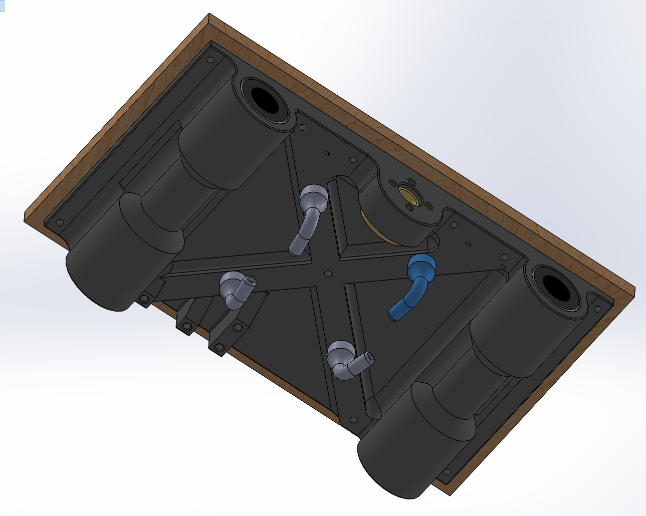
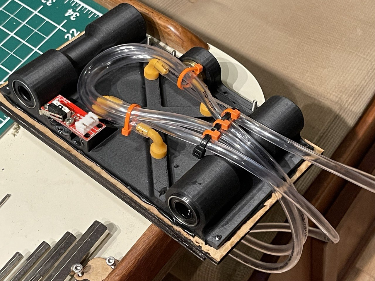
    This is a rather large 3D-printed part (remember, the entire mill only needed three large 3D printed parts as everything is fully integrated). In addition to the field of little standoffs, I added four holes for the air to be sucked out.


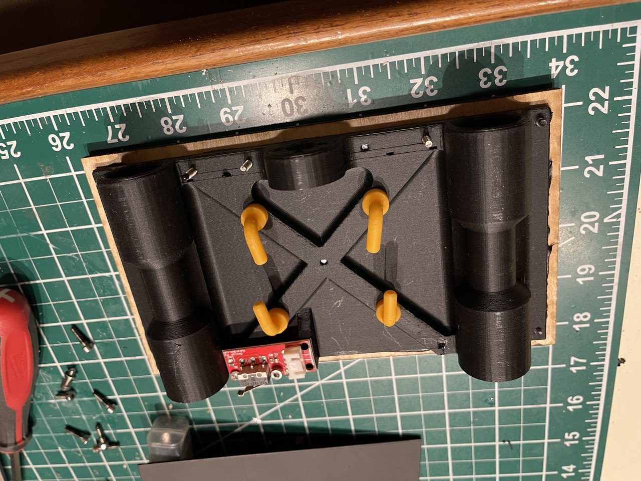
    On the underside, I added attachments for clear tubing. I think mine are just 1/4" tubes that I slide onto the 90 degree angles. These are resin printed instead of purchased and even with standard resin, surprisingly strong.

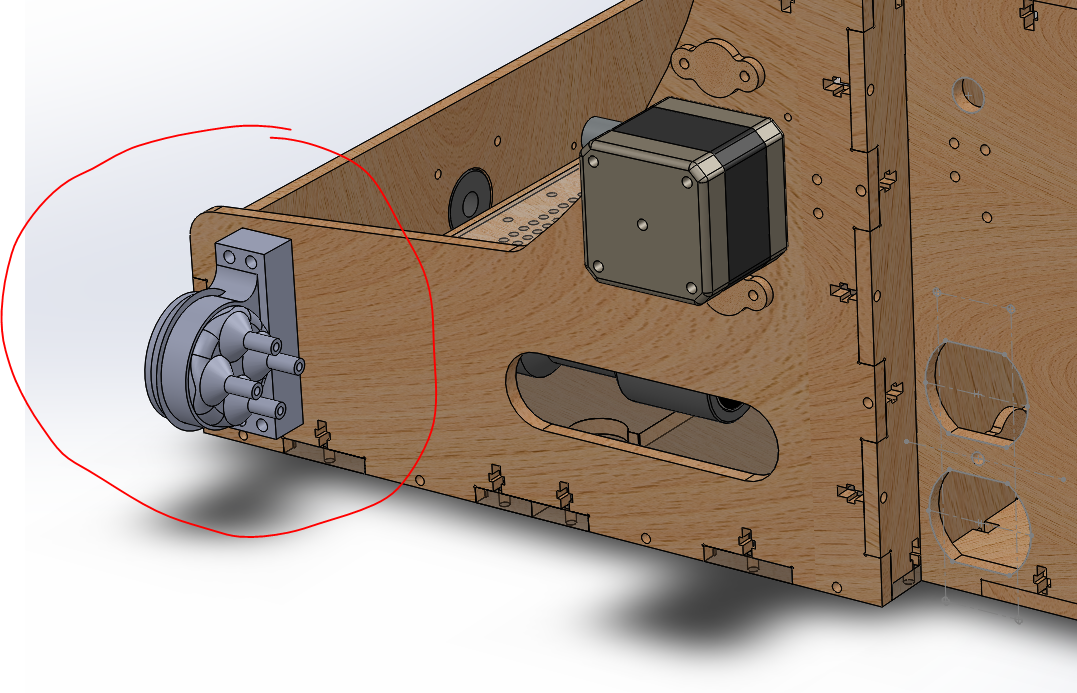
    The clear tubing then goes to my vacuum adapter that's mounted to the side of the mill:

    Here, I can just slide on my vacuum cleaner hose and everything is connected. It was a bit challenging to organize the clear tubing underneath the X-axis but with the help of various cable ties I was able to the the X-axis to move back and forth without additional resistance.

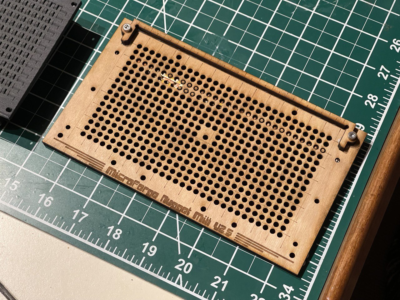
    On the top, I added a new bed. This time, it was perforated with lots and lots of holes. My laser cutter lens was dirty and the cuts barely went through but I made it work and, spoiler alert, it works amazingly well!

    After I put everything together, I turned the vacuum cleaner on for the first time and was amazed that I was barely able to move the PCB with my fingers. I can probably pull on the board with 20N before the board starts to slide. That's a lot for a 0.2mm V-endmill. All holes that are not covered by the PCB that I'm using can simply be covered using either just paper or packaging tape or a matching piece of wood! As long as all holes are covered, the suction force is great!

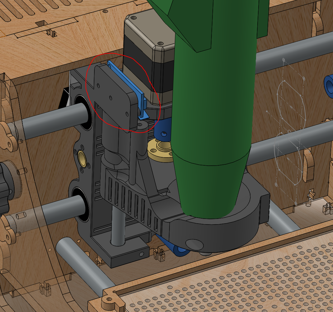
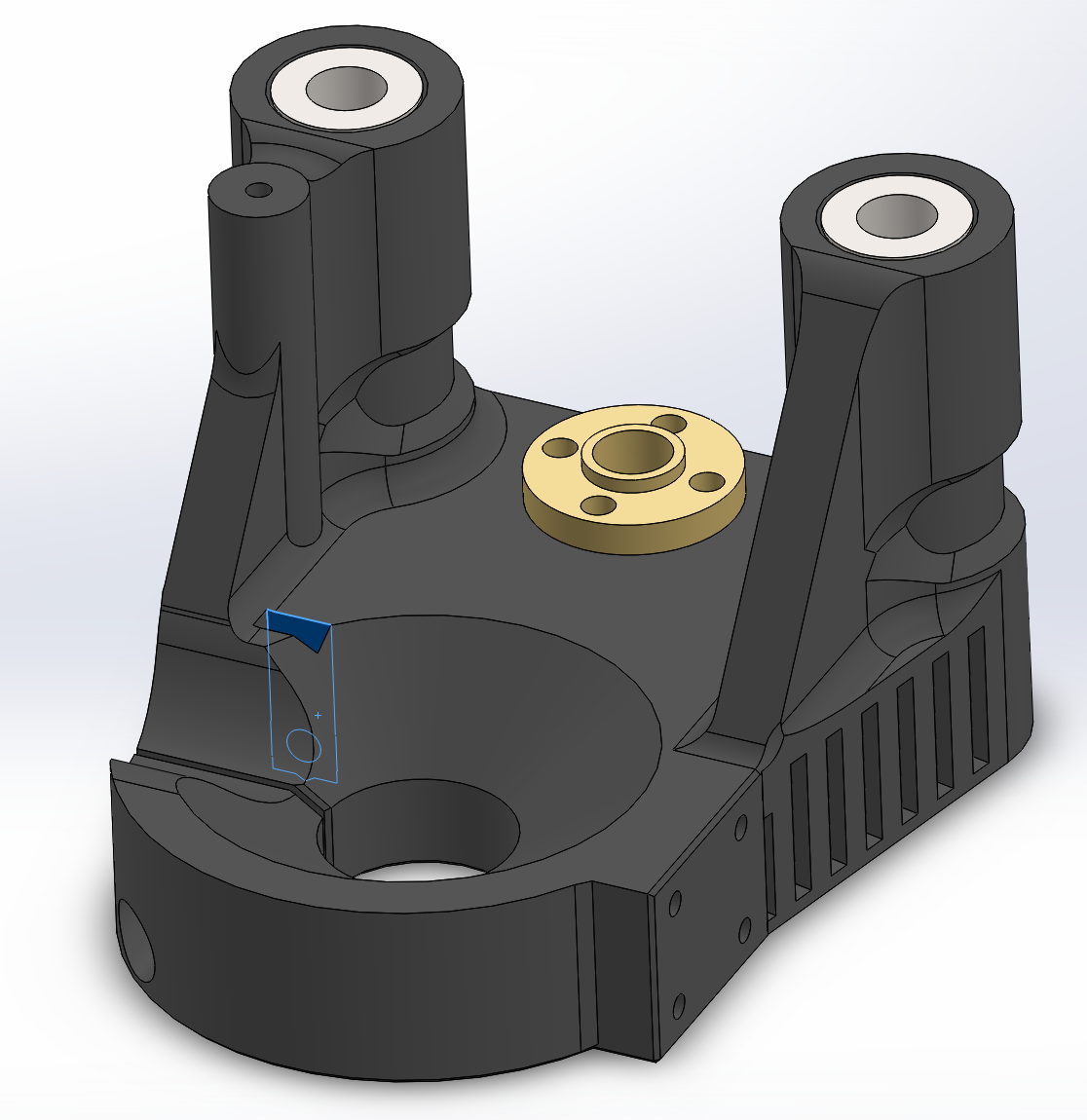
    During this upgrade process I also decided to revamp the Y-axis as well as the Z-axis. The Y-axis had a few broken plastic clips and wasn't really save to use anymore. The Z-axis desperately needed an endstop switch:

    I also finally added a slot for a 4mm nut such that I can tighten down the Proxxon MicroMot properly without ripping the threads in the 3D printed plastic.

    This works so well that for top and bottom side milling, I don't...

    Read more »

  • Updating cnc_gcode_controller and FlatCAM

    Timo Birnschein01/13/2022 at 15:10 1 comment

    cnc_gcode_controller is an amazing open source project. As far as I'm aware, it has the only open source auto level feature that properly works by probing the board, creating a height map of it, and then splitting all the gcode commands up into snippets to linear interpolating them in the Z-Axis to match the the actual PCB or bed shape. When it works, it's fantastic!

    However, GRBL1.1 changed a few things around and, of course, it didn't work anymore.

    First of, GRBL1.1 uses a separate probe pin on the Arduino and the previously used Z-MIN/MAX pins won't do it anymore. The probe pin is now also reported with a 'P' instead of a 'Z' when asked what endstops are hit using '?'.

    In the above example right after power up, the X axis endstop is reported shown in the |Pn:X| section.

    Then, when the probe pin is hit, the command to let cnc_gcode_controller or any other gcode sender know where this was, is also different so cnc_gcode_controller didn't interpret it properly. I went ahead and created some issues around it on github and the original author (Patrick) quickly reacted and fixed the issues I described. THANK YOU!

    In addition, I decided to add a few buttons to the software to make my workflow a bit easier.

    The Advanced Controls panel now contains a second row of buttons underneath "Global" specifically for "Milling".

    These buttons allow me to easily invert the X-axis and move the tool over to the other side of the bed to a calibrated location to create perfectly aligned double sided boards without the need for any alignment pins. Just flip the board over, align the same corner of the PCB used for the top side and align it with the bottom side on the bed, done.


    The Skew-Problem

    After calibrating the machine offset for top and bottom milling perfectly after many trials of milling and drilling test patterns, my mill appeared to work perfectly. As long as you only want to mill at the very bottom of the bed. Turns out, the machine is skewed. It has a parallel shift along the Y-axis resulting in parallelograms rather than squares. The lower 10mm of the board look great while the upper 75mm go more and more out of alignment with the bottom side of the PCB. All consequently drilled holes on the bottom side are therefore misaligned with the vias on the top side. Extremely annoying and in this case breaking the layout as some connections are broken now.

    At first, I was confused about this but it occurred to me that I used my $350 Chinese K40 laser to make the PCB mill which most certainly is not 100% square looking at the way it's put together. It's sturdy but there is a different between something being ridged and something being well aligned and calibrated. So the cnc is skewed because the base plate of the cnc is skewed which in turn is skewed because the laser cutter is skewed. hmmmm...

    How can I fix this? Turns out it's very easy to do in software.

    My first thought was to write a python script to ingest the gcode and translate every X-Coordinate based on it's corresponding Y-Coordinate. However, that's a lot of work and it felt like a waste of time for the number of boards I make a year.

    I found a much more elegant way to do this: In the grbl1.1 preprocessor of FlatCAM, I added an equation that just adds an offset to the X-coordinate based on Y. I just need to flip the sign for the other side of the PCB so I created a second preprocessor script that does just that. Problem solved :)

    I then presented this idea to the developer of FlatCAM which is my favorite PCB CAM software of all time. He liked the idea as it turned out his personal machine also has a skew, so he went ahead and implemented a variant of it into his software!

    In my version, I created two different preprocessors for GRBL1.1. One for top side milling and one for bottom side milling. This works well for me as I only need to change one thing in FlatCAM during the creation of the CNC commands to correct for top and bottom skew. The issue...

    Read more »

  • GRBL Mega 1.1g - Tough Transition

    Timo Birnschein12/17/2021 at 15:40 0 comments

    This morning, I spend 2.5h figuring out why the homing cycle on my mill doesn't wouldn't work after I upgraded to the latest GRBL mega. I couldn't find out where I had stored my original grbl version for this mill but it was rather old, like 0.9g and had quite a few bugs that I wasn't keen on carrying forward.

    So this morning, after much consideration, I jumped right into it, cloned the repository and tried to reverse engineer the changes I had done for the old CycloneGRBL, or whatever I used back then, to work. Turns out the changes were rather minimal and what bit me in the end was a missing pullback for homing.

    Since my mill uses an Arduino Mega256 with a RAMPS1.4 board, I needed to define the appropriate build flags in the config.h:

    #define DEFAULTS_RAMPS_BOARD
    #define CPU_MAP_2560_RAMPS_BOARD

    Then I changed what the homing cycle looks like to reflect that I don't have a Z-axis endstop switch:

    #ifdef DEFAULTS_RAMPS_BOARD
      #define HOMING_CYCLE_0 ((1<<X_AXIS)|(1<<Y_AXIS))   // Home X axis
    //  #define HOMING_CYCLE_1 (1<<Y_AXIS)   // Home Y axis
    //  #define HOMING_CYCLE_2 (1<<Z_AXIS)   // OPTIONAL: Home Z axis
    #else
    //  #define HOMING_CYCLE_0 (1<<Z_AXIS)                // REQUIRED: First move Z to clear workspace.
    //  #define HOMING_CYCLE_1 ((1<<X_AXIS)|(1<<Y_AXIS))  // OPTIONAL: Then move X,Y at the same time.
      #define HOMING_CYCLE_0 (1<<X_AXIS)                // REQUIRED: First move Z to clear workspace.
      #define HOMING_CYCLE_1 (1<<Y_AXIS)  // OPTIONAL: Then move X,Y at the same time.
      // #define HOMING_CYCLE_2                         // OPTIONAL: Uncomment and add axes mask to enable
    #endif // DEFAULTS_RAMPS_BOARD

    And for my specific setup, I'm running the SPINDLE_ENABLE_PIN on Digital Pin 9 for some historical reason, so I had to change the cpu_map.h in the appropriate place:

    // Define spindle enable and spindle direction output pins.
    //  #define SPINDLE_ENABLE_DDR      DDRG
    //  #define SPINDLE_ENABLE_PORT     PORTG
    //  #define SPINDLE_ENABLE_BIT      5 // MEGA2560 Digital Pin 4 - Ramps 1.4 Servo 4 Signal pin
      #define SPINDLE_ENABLE_DDR   DDRH
      #define SPINDLE_ENABLE_PORT  PORTH
      #define SPINDLE_ENABLE_BIT   6     // MEGA2560 Digital Pin 9

    After that, it was a matter of setting the correct configuration parameters using using the GRBL config that can be set at runtime (an amazing feature, btw. I wish Marlin would have something like that, too).

    $0=10
    $1=127
    $2=0
    $3=6
    $4=0
    $5=0
    $6=1
    $10=31
    $11=31.000
    $12=0.002
    $13=0
    $20=0
    $21=1
    $22=1
    $23=0
    $24=50.000
    $25=1000.000
    $26=250
    $27=0.500
    $30=0
    $31=0
    $32=0
    $100=800.000
    $101=800.000
    $102=3200.000
    $110=1800.000
    $111=1800.000
    $112=450.000
    $120=30.000
    $121=30.000
    $122=10.000
    $130=162.000
    $131=107.000
    $132=30.000

     The important learning that cost me almost 2h of my life is $27=0.500. This defines the pull back distance after the homing switches have been hit during homing for the first time. I didn't want any pullback, I thought, and on my old setup this value was set to 0mm so I replicated that right after flashing without checking anything. However, GRBL 1.1 reacts differently from 0.9g as it REQUIRES a pullback distance to be defined to be able to home at all.

    If the pullback distance is set to 0mm, it will go straight into an alarm state once the endstop was hit. In the end, it was a test like: "Yeah whatever, I'm running out of options...." shot in the dark. Target hit. Everything worked all of a sudden... dude.

    What really bothers me, though, is that LaserGRBL still doesn't like the mill. I thought it doesn't like GRBL0.9g but it still won't connect to my mill. It's works fine with the laser cutter and apart from the lock state it wakes up in. But according to LaserGRBL, that's acceptable. Hm. I guess I have to continue to work on cnc-gcode-controller and make that software work for me with all it's quirks and bad performance gcode streamer.

  • High Voltage Wiring Diagram

    Timo Birnschein07/15/2017 at 22:00 0 comments

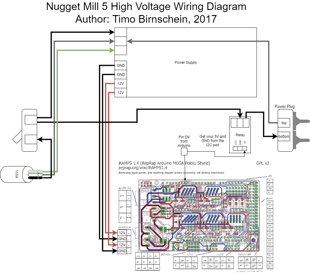
    was asked to create a wiring diagram for the NuggetMill5, so here it is.


    I left the basic stuff for stepper motors and endstops out because I already described it in my logs below.

    Motors are standard. Just make sure they move in the right direction with my configuration. If not, please turn the plug around and it should be fine. I stole the 5Volts for the relay from the I2C port. I also needed to use the MIN EndStop inputs for the three endstops that are supported with this version of grbl instead of MAX as described for the original grbl. Please keep that in mind.

  • pcb-gcode bugfixes and github

    Timo Birnschein07/08/2017 at 20:53 0 comments

    I realized another bug when milling my first actual project on the mill:

    pcb-gcode, even though many people seem to be using it and the documentation seems excellent, seems to have quite a lot of bugs that are easy to fix due to Eagles C-like scripting language.

    The latest bug I found and hopefully just fixed is the issue that spotting holes during the etch step drills all the way to DRILL_DEPTH right after the first hole was spotted properly. Spot drilling is supposed to help a manual drill step by creating a center hole for the drill press to work with.

    However, after the first proper spot drilling, the V-shaped engraver bit got punched into the PCB all the way to the drill depth (1.65 mm) which widened my holes quite a bit, shrinks the restring unnecessarily, it costs time, it wears out the engraving bit and it's generally... simply a bug! I don't yet understand why the first hole and all other holes are handled separately but I guess I will find out as soon as I work on my next project.

    To make things a lot easier, I also created a github repository for pcb-gcode. I have no idea why the original author is not using github to distribute the software...

  • First actual project

    Timo Birnschein07/02/2017 at 22:36 0 comments

    There are a couple bugs left in the configuration and some gcode issues like the etch step is also used for drilling "again" for no reason. I need to fix that in the pcb-gcode script. However, the results are really cool!

  • Happy 4th of July!

    Timo Birnschein07/01/2017 at 21:21 2 comments

    Make something cool today!

  • What the YAD?

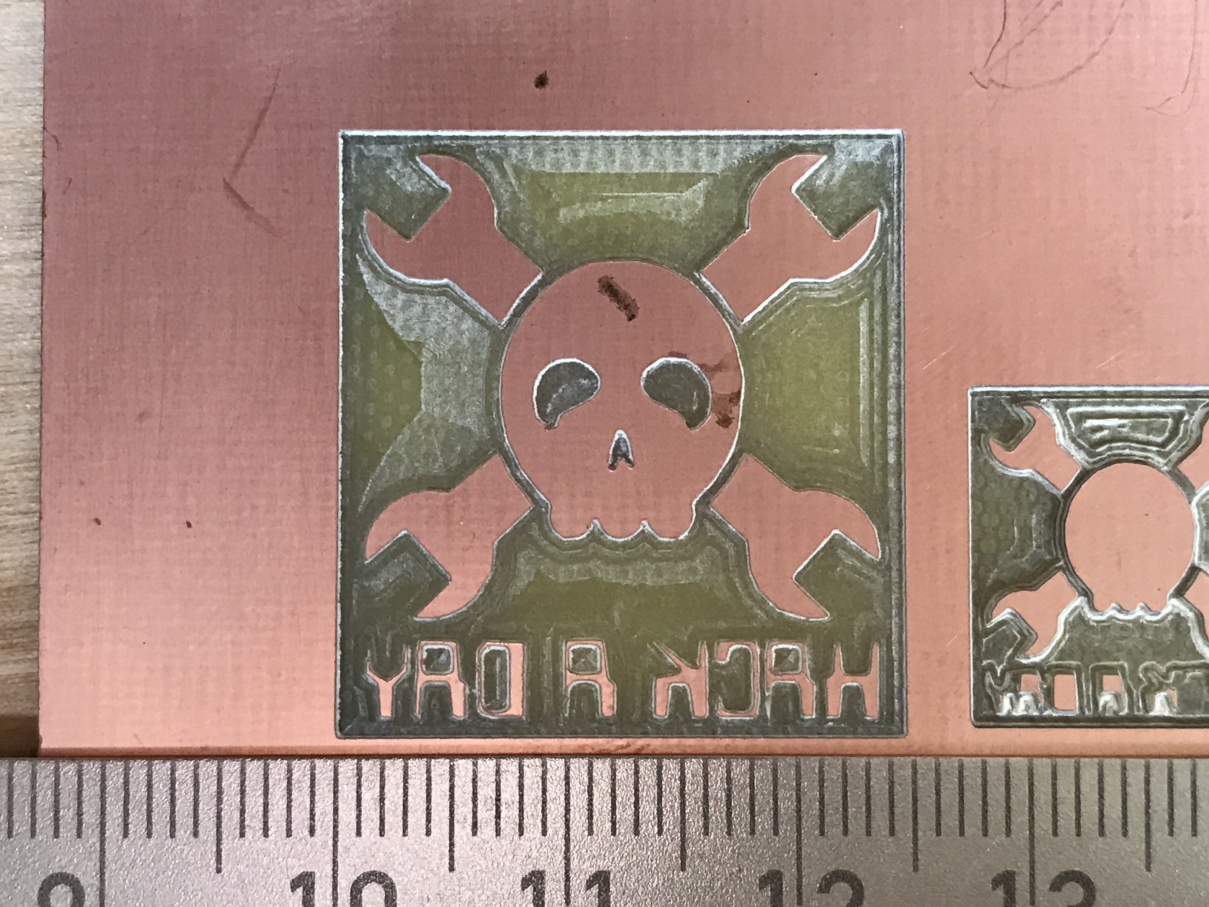
    Timo Birnschein06/25/2017 at 01:27 2 comments

    The moment you realize....

    Your X-axis is inverted. And I was like... Why the hack does the 'H' look so weird!!?? .... [long break] ... oh it's a 'Y'... darn.

  • Calibration Wizards for Ease of Use

    Timo Birnschein06/24/2017 at 23:26 0 comments

    Today was a good day. After realizing that rewriting lost instructions makes no sense at all since I should be able to create a proper wizard for machine calibration in the same time, I did just that.

    With grblController you now can

    • Mill double sided PCBs without any hassle
    • Calibrate / mill down your X-Axis Alignment Fence to be 100% parallel to your X-Axis
    • Perform the X-Axis calibration for milling the bottom side of a PCB

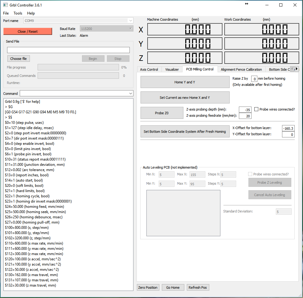
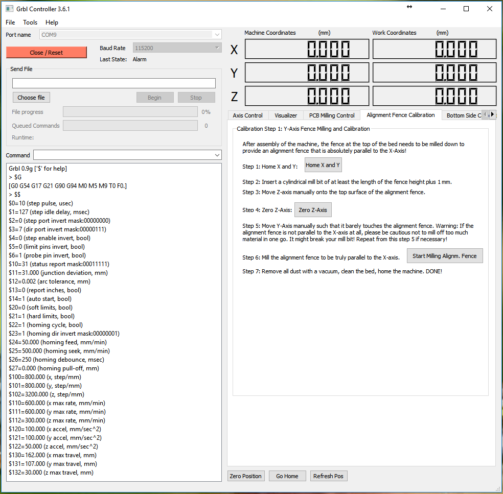
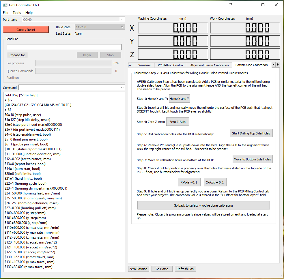
    Since my goal is to make everything as simple as possible to the user, I created a step by step instruction set on new tabs in grblController:

    Above you see the options you have available for PCB milling. I think, this should give you all the tools that you might need to mill your double sided PCBs. But since you need to calibrate your fresh machine first, I added the calibration tabs.

    This tab provides you with step by step instructions to properly mill down your X-Axis alignment fence. Please use one of these mill bits to mill the fence down and to make it absolutely parallel with your mills X-axis.

    The bottom side is a bit more interesting, even though it will take much less time to get right. Just follow the instructions and you will end up with a perfectly calibrated machine.

    One add-on I'm thinking about is storing the actual negative space coordinate system for milling the bottom side of the PCB into the grbl controller itself and not the software. It could be beneficial if you plan on moving the mill to another place and use it with different computers from time to time. But for now, I think it's fine that the settings are stored properly and platform independent on one computer.

View all 19 project logs

  • 1
    Step 1

    Printing the parts:

    Please use a slicer that supports calibrating holes properly. I use KisSlicer for slicing, there is a free version available that supports printing one type of part at a time. You may print multiple of them at once but only the same part. I love it because it allows me to print 15 mm holes at exactly 15mm so that I can press my linear bearings into the holes and don't need any additional thing but a vice to fix them in place for the lifetime of the part. It's also just $42 or so and its generally really good and requires more attention by 3D printer owners!

    Since you can do what you want and PLA and especially ABS will always warp at least a little bit, I designed the parts with warping in mind. I added tension releasing cuts where possible and all functional surfaces are facing away from the print bed. Therefore, you have to press the brass nuts in on the TOP side of your prints and never on the one that was flat on print bed. I changed the design of the X-axis (going from left to right when you look from the front) so that the next person to print these parts puts the brass nut on the onside of the X-axis because that side is more likely to be flat and 90 degrees than the print bed side.

    Since the parts are pretty large, the print of each takes many hours. Between 8 and 11 hours in my case at 0.2 mm layer height and 33% infill.

  • 2
    Step 2

    Laser cutting the wooden enclosure:

    This proved to be a challenge on my K40 laser cutter. I bought this super cheap $5 a sheet plywood from home depot and hoped that I could cut it well because I did it before. But I was wrong. Cutting multiple parts in one go seems to heat up a component within the laser so that the cutting power goes down. At first randomly, later permanently so that the system needs a cool down phase. Even changing the final focus lens to a 38.4 mm lens to get more power in one spot did only improve the situation but not completely eliminate the issue that some parts just wont cut after cutting a few before. It works, but it doesn't work well. I suggest to honer your local maker space and ask to use their laser cutter for a tip. They will cut all the parts in no time, you get the precision you want and you get to know some very nice people!

    I glued the parts together using wood glue. It is very easy so do since you can just lay them side by side and apply a bead of glue. Fold the parts and add M3 x 12mm screws and M3 nuts. Tighten the screws but please don't over-tighten them. The wood will crack and it's not necessary. The screws are more an accessory to get the mill into shape and to support the glue while drying.

  • 3
    Step 3

    Building it up:

    I highly suggest to order the hardened steel linear rods cut to the proper length! They are... VERY hard. Using a hacksaw to cut them will cost you more time and money than just ordering them at the proper length. I used an angle grinder with a thin 1 mm cutter to cut them and even that took some time at a proper workshop. Most ebayers except these requests because they have to cut them anyways.

    Putting the rest together should be pretty straight forward.

View all 9 instructions

Enjoy this project?

Share

Discussions

Paul McClay wrote 03/31/2021 at 07:30 point

Hi Timo. Thanks for the skull/follow for #Minamil! It won't do 100x160mm, but I wonder -- since you've had this machine for a few years by now -- how much of what you do with this could be done in 55mm+ x 55mm+, or maybe 70mm x 70mm?

  Are you sure? yes | no

Andrew Herdman wrote 07/12/2017 at 02:05 point

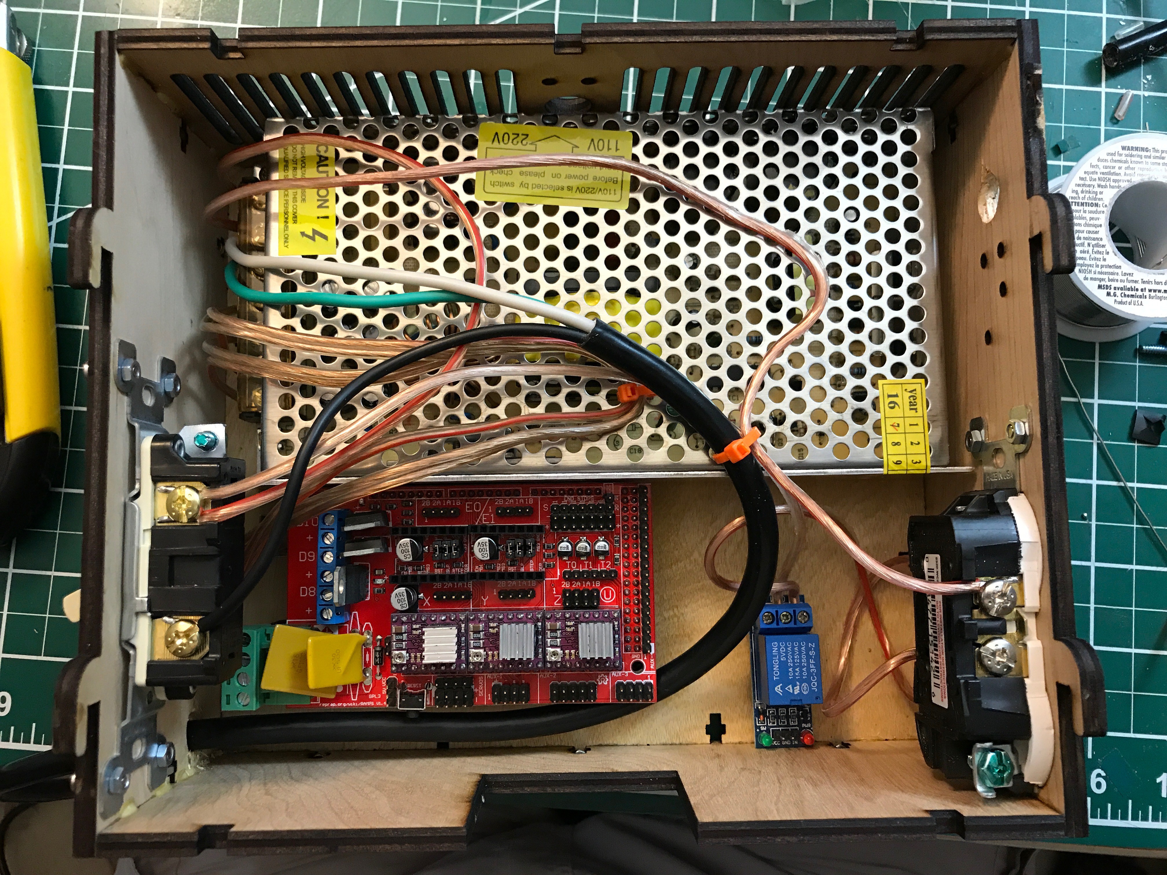
Great project, I'm building one, I've got all the wood laser cut and am collecting the other items, some will be quicker than others.  Do you have any pictures of the electronics section of the project to share?

  Are you sure? yes | no

Timo Birnschein wrote 07/14/2017 at 01:38 point

Hey Andrew, this is great! Thank for building one! It feels really good, if I'm honest :)

I will gladly work on a schematics for the power back pack. Generally, it's simple.

Power cable goes in, through the Home Depot light switch, to the power supply and also to the relay for the spindle and from there to the 115V power outlet of the spindle. From there, the other phase is routed back to the cable (I just used the power supply as a terminal block) and also from the power supply back into the 115V cable.

The only real trick here is that the relay needs 5V active high and you don't have that for free on the RAMPS 1.4 board. Only as open collector (essentially active low) through a MOSFET that is used for one of the heater elements of a 3D printer. But to be able to use M3 and M5 to start and stop the spindle, you need to solder a wire directly to the D9 pin on the ramps board. Not nice, but you won't need to change that board ever again.

Give me a couple of days. I assume, you'll be waiting for parts anyways. :)

  Are you sure? yes | no

Andrew Herdman wrote 12/11/2017 at 22:00 point

Hello, the build continues!  I've got all the parts, but ran into an issue with the 3d printed pieces (as you mention in the build log).  I can't use Kisslicer on the printer i'm using (Makerbot).. and lo and behold, the hole is about 0.4mm too small.  I tried increasing the size of the dimensions by 102.5% on the axis's with the holes, that works (for the bearings) but the part is now dimensional incorrect, I was just going to fix up the dxf files for the new dimensions, but then checked harder, and yup, the 3d printed parts on the dimension I didn't change, are affected.  Could you provide me access to the solid models of the 3d stl files?  I use Fusion 360 and stl to solid isn't it's best cup of tea.  I've got a 21mm and 15mm twist drill bits ordered, but they are weeks away from arriving...


Thanks

  Andrew

  Are you sure? yes | no

Timo Birnschein wrote 12/12/2017 at 03:42 point

I can't reply to your second message for some reason but I uploaded igs files for you to import into whatever software you use. It's a standard format and you should be able to import them just fine. Please let me know.

https://cdn.hackaday.io/files/253561084831104/X-Axis.IGS

https://cdn.hackaday.io/files/253561084831104/Z-Axis%20UpperRodHolder.IGS

https://cdn.hackaday.io/files/253561084831104/Z-Axis%20RunCat.IGS

Also, there is a tool available that converts the gcode from kisslicer into the binary format that your makerbot (or my Malyan M180) is using. https://cdn.hackaday.io/files/253561084831104/GPX%20Converter.rar

  Are you sure? yes | no

Jon Raymond wrote 07/04/2017 at 19:47 point

Wonderful and well thought-out project.  Is it possible to include STEP (or source) files as well for the 3d Printed parts so they can easily can be modified?

  Are you sure? yes | no

Timo Birnschein wrote 07/14/2017 at 01:44 point

Yes. I stepped out the entire NuggetMill5 https://cdn.hackaday.io/files/253561084831104/NuggetMill5 - step.rar

Cheers and please let me know what you modify!

  Are you sure? yes | no

Patrick wrote 07/02/2017 at 21:46 point

Maybe you can try AtCore to control your CNC.

https://github.com/KDE/atcore

  Are you sure? yes | no

Similar Projects

Does this project spark your interest?

Become a member to follow this project and never miss any updates