ACROBOTIC Industries
-
Programming the ESP-01 | Attempt #1
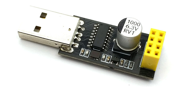
02/26/2018 at 00:44 • 0 commentsThe next step was loading some code into the ESP-01. This module doesn't have a built-in USB-to-Serial adapter, so we needed to build or purchase an external adapter. Though we've built some in the past on a breadboard, we didn't want to deal with messy wiring, so we went for the latter of the two options and picked up a cheap ESP-01 programmer on eBay.
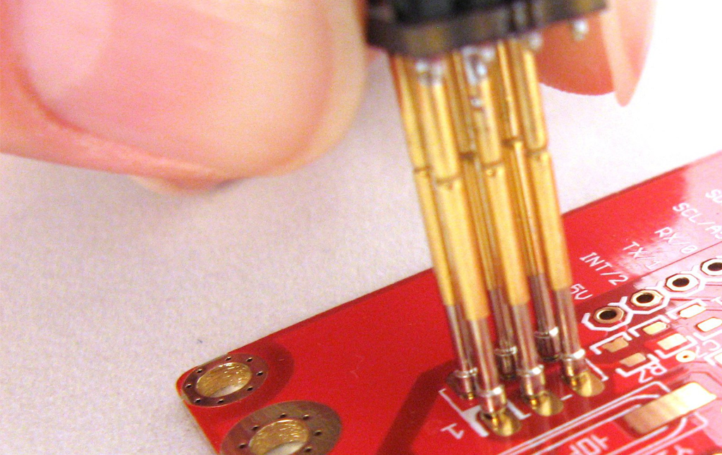
The thing is that we want to remove the header of the ESP-01 so that the LED board sits flush against its back side, so we needed to connect the programmer and ESP-01 module without using the pin socket. In such cases where we don't have a header to use, we turn to pogo pins for making temporary-but-robust electrical connections between PCBs.
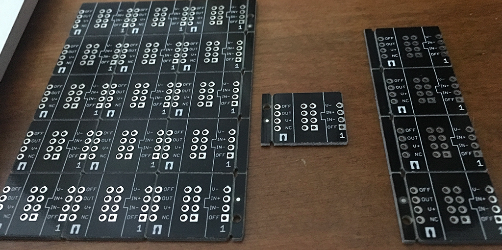
Luckily we had some 2×4 pin-to-pin breakout boards for a different projects that came in very handy!
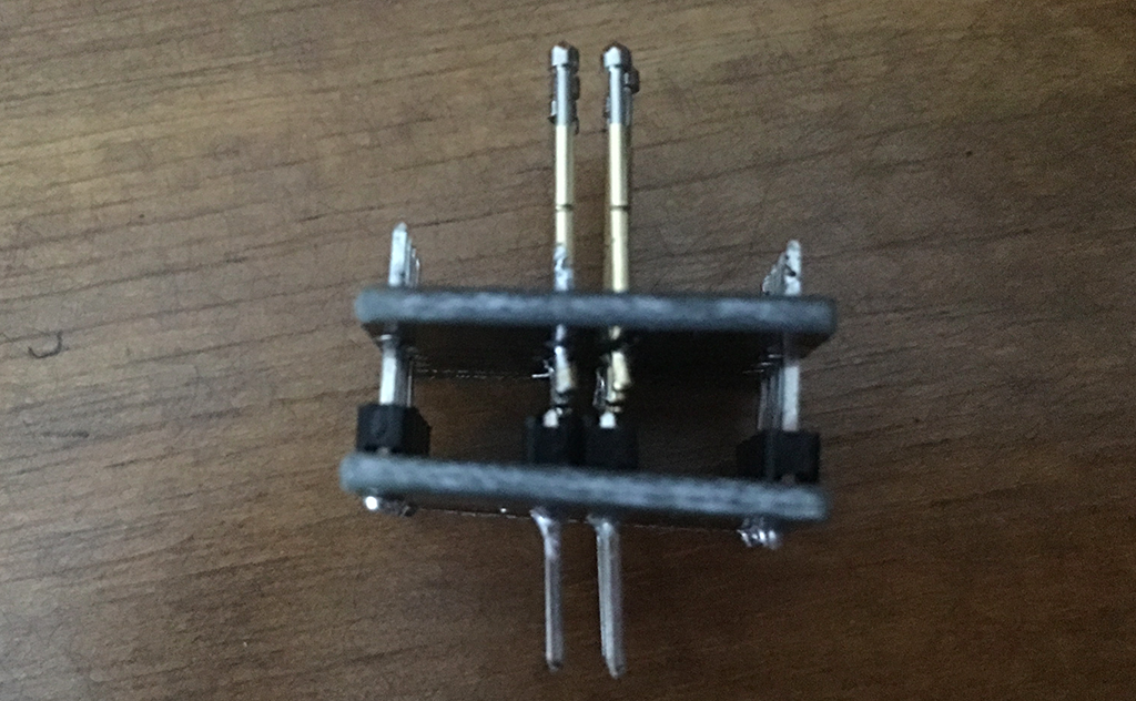
Our first attempt, without too much thinking was to create a 2x4-to-pogo pin sandwich board that we could simply plug into the header of the ESP-01:
Unfortunately this didn't work because we only have access to the top side of the ESP-01 as the pins on the back of the module are soldered to the LED board, which doesn't have pads/pins on its top site. As such, the connections are reversed by a mirror image.
-
Getting Started
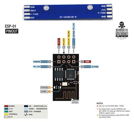
02/15/2018 at 06:50 • 0 commentsWith some of the parts in hand, the first thing we need is to connect the ESP-01 and the 8-bit NeoPixel LED board. Given the goal of a minimalist design, we choose to mount the two boards back to back. Conveniently, the spacing of the pins and pads is the same (0.1" pitch) so they physically line up. So let's consider now the pinout of the two:
![]()
Just for kicks and giggles we'll remove the pin header from the ESP-01, and use 3 pins from its top row to connect to the LED board so that the connections are as follows:
ESP-01 | LED board
GND-----GND
GPIO2--4-7VDC
GPIO0--DIN
This is not a great idea because we plan on using GPIO2 to power the LED board even though it won't provide neither enough voltage (3.3VDC max) nor source enough current (50~60mA max). ¯\_(ツ)_/¯
To avoid any interference from the second GND pad on the LED board, and the pin with which it lines up on the ESP-01 (U0RXD or Rx), we remove the pad by applying a bit of heat with the soldering iron.
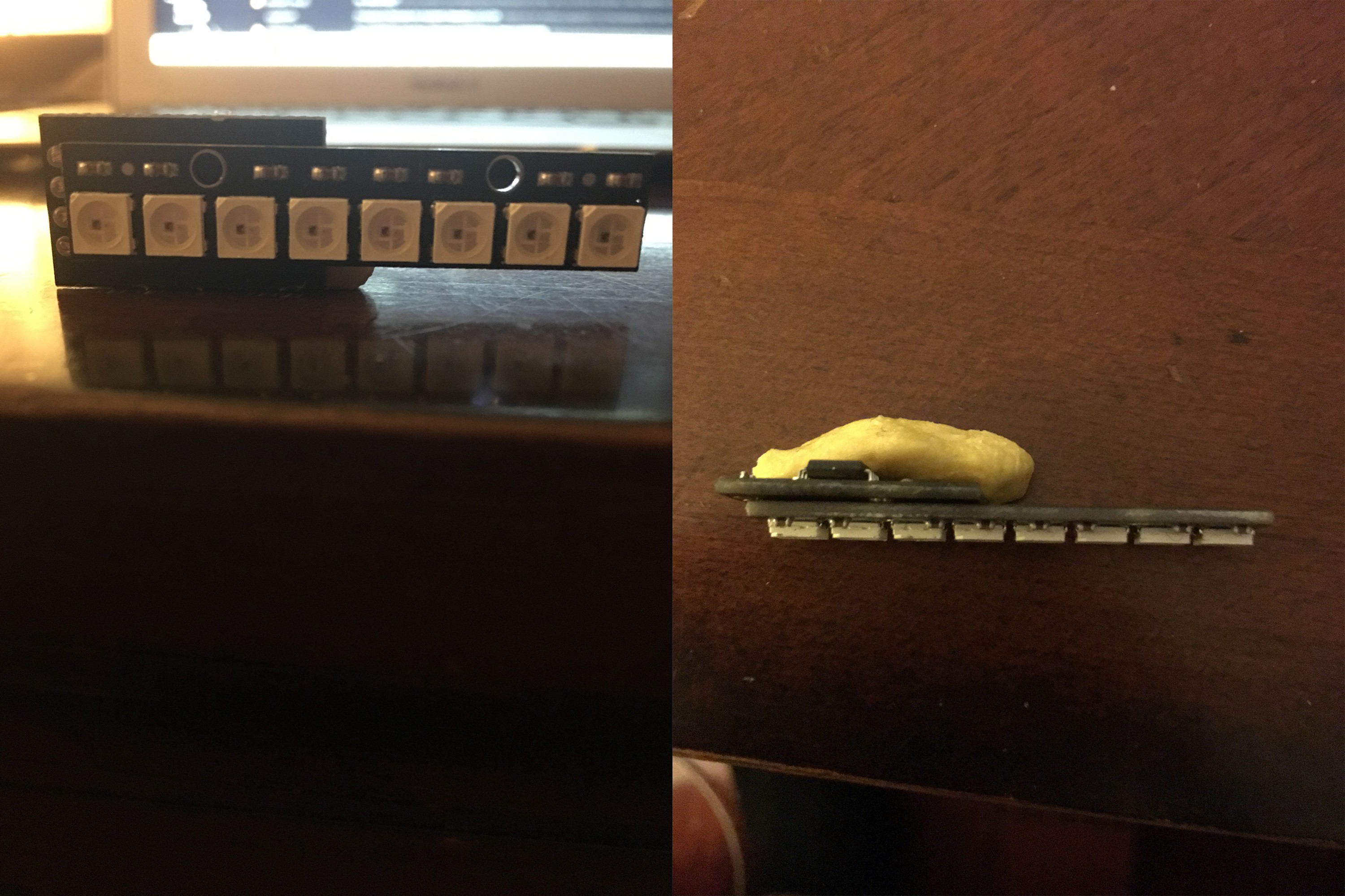
After soldering the two together this is what we have:
![]()
Now we move on to building a little programmer to load our test code!
KronoX | Light-Encoding Timekeeper
Using the versatile ESP8266 to control an 8-bit array of LEDs for displaying a single-digit binary clock!