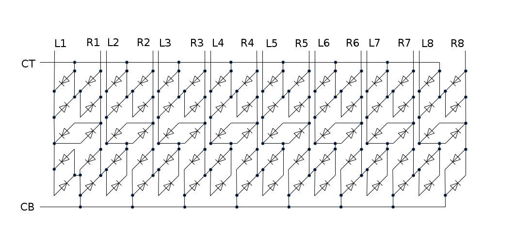
Here is the charlieplex SMD LED matrix circuit implemented on the PCB:
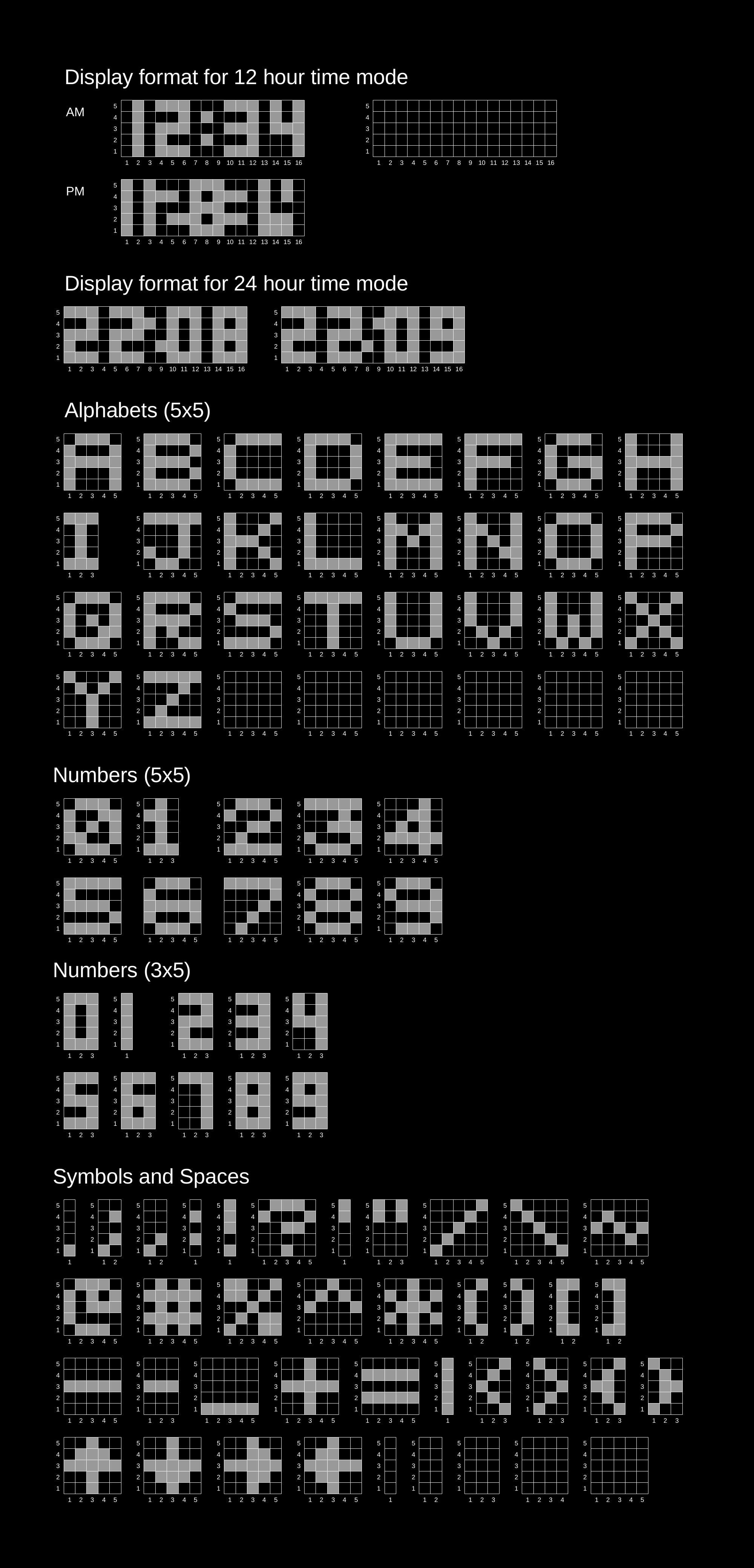
Here is the character set for the watch display:
Scrolling LED display on your wrist
To make the experience fit your profile, pick a username and tell us what interests you.
We found and based on your interests.
Here is the charlieplex SMD LED matrix circuit implemented on the PCB:

Here is the character set for the watch display:

A different idea is to add a small solar panel/cell with some changes:
Switching over to an ARM based solution is much better than an AVR+RTC chipset solution. Been looking at the STM32F030 chip and it is a perfect fit for this application! It has the following very desirable characteristics:
Need to use the NDK crystal mentioned in the clocking application notes (page 28). The NX3215SA part is available on aliexpress.
All information for getting started on using STM32 bare bones is mentioned in this excellent article (we don't need no dev boards!) :
http://kevincuzner.com/2016/05/22/dev-boards-where-were-going-we-wont-need-dev-boards/
Or maybe a low power version like the STM32L031 or STM32L051. It works down to 1.8V. Its actually less expensive than the ATMEGA88V (in single quantities on digikey)
The dense LED matrix has some issues:
Create an account to leave a comment. Already have an account? Log In.
Hi Vincent. I'm glad you like my project. I am not sure when I can get it on tindie. I will surely let you know when I do. Thanks again :-)
I like the way you're pointing and challenging the LEDs side leaking issue that actually seems to be a major point on this kind of dense matrix display. Looking forward your sign Vikas :)
Thanks @Vincent. For the light leakage, I am thinking of going with the epoxy solution which seems would work and look the best. I still need to test it out.
Nice project!! Do you have a github repo to download all the files? Could you share them?
Thanks!
Thanks @Alexis . I'm still in the process of putting the files up on github. Will let you know once its on there. BTW, which part of the project do you want to look into and interested you? Just curious. Is it the code, PCB etc?
Thanks a lot!
Yeah is the PCB and the code above all. I really like to check PCBs and try to modify them, or making them smaller etc... Also, this allows me to make the project for myself and have some fun while doing it. The code is also important because I must tell you that I only know a bit of coding with the arduino IDE.
So all in all, with your github repository, I would check if I can upload the code and if so, I would start looking at the board and ordering the components to make one.
Again, your project is really cool!
Hi Vikas, very nice project! Have you considered reverse mount leds? That could potentially solve the light leaking problem you encountered with.
Thanks for the suggestion. Yes, I guess reverse mount LEDs would solve the light leakage issue. In my PCB layout, there is a CR2032 retainer mount on the back side which overlaps the matrix, so it might be difficult to implement. Will try it out.
Have you considered connecting a 32.768khz crystal directly to the atmega and running an RTC routine through timer 2? It's what I did in #bioloop and it allowed me to keep accurite time without having to worry about a didicated RTC
Thanks @qquuiinn for your comment. I looked into this. The problem is I need a pretty fast CPU (maybe about a 1MHz at least) to compute and scan the LED matrix. Because the AVR does not have an internal PLL to multiply frequencies, I had to use the minimum frequency crystal required. I could run the RTC routing in software using the higher frequency but that would compromise timing accuracy as the higher frequency crystals are not that accurate. And also that I did not have enough space on the PCB and pins on the microcontroller to interface to and RTC chip over SPI/I2C. So, I thought of the integrated solution of using an STM32 uC which has the low speed oscillator built in.
If you're thinking of switching over to the STM32F030, beware that some of the lower end STM32 parts with low pin counts don't support an external 32khz oscillator. This is because on the F030 series, there are dedicated pins for the high speed oscillator, and for the low speed oscillator, and some packages are missing the low speed oscillator pins. Open your desired package in CubeMX and check that it actually allows you to select the oscillator!
Namely, the 32QFP package you mentioned doesn't support an external low speed oscillator, even though it has an RTC!
You can use the HSE to run the RTC. Unfortunately that means no sleep mode if you want to keep it running. :( If you already use external RTC chip, then that's not an issue.
good point, that would be the use case of the RTC (or using the low accuracy internal low speed oscillator). Vikas specifically wrote "32.768kHz oscillator on-chip. Just need to hook-up the crystal" so I wanted to warn him before he gets too far into development.
Should take a look at STM32L low power series chips.
There is a 48 pin QFN STM32L100R8/RB with 32kHz oscillator. It can run down to 1.8V, 214 µA/MHz Run mode.
STM32L031 in 32pin LQFP package with 32kHz oscillator. Runs down to 1.65V and even lower power.
Thanks @K.C. Lee for the STM32L031 chip recommendation and the other comments
Thanks @drojf. Appreciate your heads up. Looking at the datasheet for the STM32F030, it seems I can connect 32kHz crystal onto the OSC_IN and OSC_OUT pins. I'm new to the ARM world and did not know about the separate pins for HS osc and LS osc. Also did not know about the pin omissions in different packages. I need to read the datasheet in detail. Thanks again
This project looks very interesting. Is there a git repo for it?
Hi Laen. Thanks for your interest in my project. Wouldn't have been possible without your service. I haven't created a file repo yet. I will let you know as soon as it is done.
How many layers is your pcb?
I have a project where an smd matrix that dense would be really useful
The LED matrix is implemented in a single layer and that is the differentiating aspect of the layout. I will upload the PCB design shortly and you can see how it is done. If you want to reuse that pattern, be aware that the LEDs are arranged in a charlieplexed manner and hence only one LED can be turned on at a time. That's the tradeoff for getting such a dense matrix. But for my application, it seemed reasonable.
Congratulations - now you can design and order a case for it :)
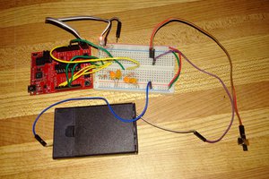
Its nowhere close to completion yet. The picture is that of a prototype to check if the multiplexing scheme would work
Thanks. I get it now. You were referring to the 3D printed parts prize. Yeah. I was thinking of making a case for the watch using acrylic sheets. But I can design and get it 3D printed now. Cool.
So 10 pins control 80 LEDs? I love charlieplexing! There's a trick to get a not so complicated layout for a matrix - draw a 10x10 matrix, cross of a diagonal and skip a row/column reconnecting everything. But how will you do that with a 5 x 16 matrix?
Hi davedarko. Yeah, charlieplexing makes layout tough. So, to make it possible in a single copper layer, I had to leave out many charlieplexing combinations. So, I'm using 18 pins to control 80 LEDs. I'll be updating the layout pictures soon.
Become a member to follow this project and never miss any updates
By using our website and services, you expressly agree to the placement of our performance, functionality, and advertising cookies. Learn More
 ClockLoop
 Mikhail Svarichevsky
 Petri Varsa
 Steve Pomeroy
Hi Vikas, this project is amazing.. Turning around for month and always come back to it :) when batch on tindie? :))