Close
0%
0%

EMDrive/satellite

Developing a small fuelless microwave thruster

Similar projects worth following
The EMdrive is a new type of thruster - recently invented by Roger Shawyer & Guido Fetta.
Unlike other propulsion systems which need to repel mass to produce thrust, the EMdrive can convert electrical energy into thrust directly.

There are endless uses for an EMDrive - in terrestric and in space applications.

A working EMdrive would start a revolution in spaceflight, enabling manned deep space exploration.

Several builds have been made worldwide (eg Chinese University, NASA), many show positive results. This topic is still quite new and needs a lot of research.

Most EMdrive builds work with frequencies around 2.4 GHz because a high power RF source for them can be made out of a microwave oven magnetron.
My attempt is is to build one which works with 24GHz, which reduces the form factor significantly and makes it possible to be used in small satellites.
A so small EMdrive could be flown to space for 20000$ on a pocketqube satellite.

OVERVIEW

-------------------------------------------------------------------------------------------

The EMdrive is derived from a closed cylindrical microwave waveguide. The main difference is that one end is larger than the other. When RF is fed into the cavity and a resonance is achieved - according to Shawyer a thrust force will occur.

---

The first builds have not been summarized due to documentation cleanup process

---

EMDrive V3

===============================================

The V3 is a silver cavity build, fed by a fully controllable RF source capable of beeing tuned between 22 and 26 GHz.

The reflected power can be measured in amplitude and phase.

First measurements with acoustic vibrations (by OOK modulation of the RF source) show a force near the designed target resonance frequency. The last experiment is reproducible and shows clear signals. Further tests must be performed to check for directivity of the force.

PS: Many many thanx to all the people who gave us very helpful hints how to improve the system. It has been an exciting ride for us until now, and we hope to provide a functional Baby-EMdrive soon

Special thanx go to TheTravellerEMD, Marvin Macportain, Keegan Reilly, Aurelio Chargb Ramos

EMDrive V4

===============================================
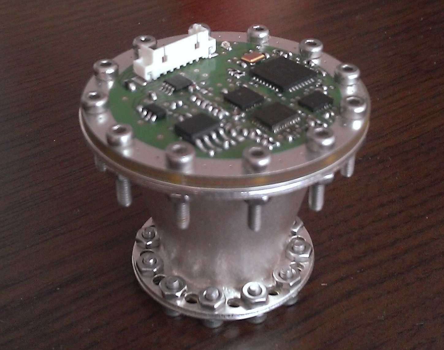
This build was a complete integrated version which has been tested at the TU Dresden with Prof. Tajmar.
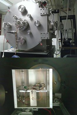
It should have been the flight version for our satellite in case the test would heve been more successful.

We had thermal issues during testing, with temperatures of the amplifier rising up to 90°C.

This led to a massive power derating in the amp.

We had to reduce power to keep the temperature low, so the final force was only slightly above the scale´s resolution.

Other effect like lorentz forces and thermal deformation had a significant pattern in the measure plot.
Tests have been made for 0°, 180° and 90°
Results are not for publilcation yet - we will perform further tests with version 5.

EMDrive V5

===============================================

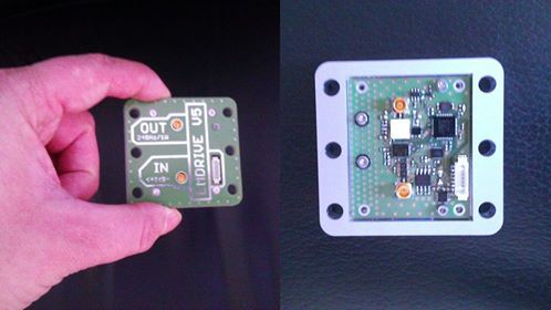
This is a development unit - derived from the V4 - which is intended to be tested at TU Dresden. It has some improvements to solve the problems that we had during testing of the V4.

It has an amplifier with better efficiency and is well thermally coupled to the casing for better heat management.

The new silver cavity geometry has an improved shape based on a proposal in Shawyer´s actual patent paper.

This shape will ensure that the pathlengths of the reflected waves on the longitudinal axis of the cavity is always kept to a multiple of lambda/2 of the resonance frequency.
  • New kind of thruster in development

    Paul Kocyla07/19/2017 at 20:34 1 comment

    Just a quick update after a long time:

    The Dresden University will probably continue measurements on the BabyEMDrive thruster with an improved torsion scale. It can resolve 20nN.

    Please check out another promising technology for propellantless propulsion. I decided to share the development and tests on a Mach Effect Thruster:

    https://hackaday.io/project/26013-mach-effect-thruster-xperiments

  • Tests

    Paul Kocyla03/23/2017 at 21:20 1 comment

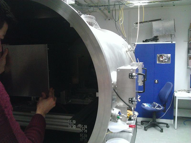
    In February the EMDrive V6 has been under test on the Technical University Dresden.

    As the pretest-board didn´t output the expected power, I made a quick redesign right before the test date.
    The output after a day in vacuum was around 500mW, that´s "only" 3dB less than the desired 1000mW. Not so bad for a simple 4-Layer board.
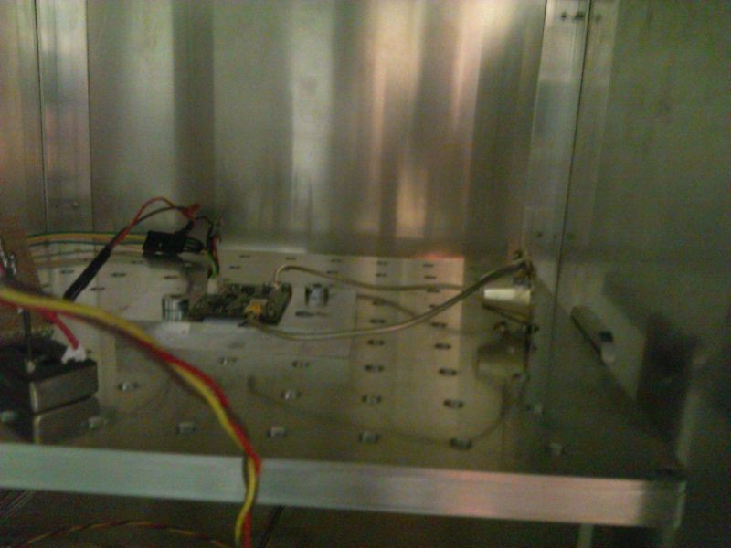
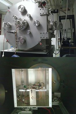
    Here is the board inside the scale box:
    I am not allowed to publish detailed results, but some information upfront:

    The thermal drift was much bigger than the possible thrust - anyway the force is depending on the frequency and seems - I say seems because that´ s only a quick observation - to be proportional to the amplitude of the resonance peaks.
    I was only able to spend two days in Dresden so the following long duration tests has been made without my presence.
    Possible forces are lower than 0.1µN, it´s still not 100% to say without eliminating the thermal drift, so we have to wait until this problem is solved.
    The thermal drift shows always in the same direction and disturbs the interesting signal into uncertainty. So thrust is not confirmed but also not busted yet.
    From my side - the Baby EMDrive is completed, unless an affordable amplifier with a significantly higher power appears.
    There is an IAC abstract from Prof. Tajmar submitted about this EMDrive with details available on the conference beeing held in September this year in Australia.
    Thanx to the many interesting discussions and suggestions.
    Special thanx go to Prof. Tajmar, Matthias Koessling and Marcel Weikert for making the measurements possible, and Dave, who boosted the project by financial help - hope we get some thrust out of it so we can send it to space.

  • Pre-Test smulations

    Paul Kocyla02/05/2017 at 16:18 1 comment

    Jamie (monomorphic) ran a simulation on the new EMDrive V5 cavity model. Great work and many thanx!
    He detected two modes - would correspond with my two resonance peaks on the real thing.

    Kein automatischer Alternativtext verfügbar.

    Kein automatischer Alternativtext verfügbar.

  • New board ready for testing

    Paul Kocyla02/02/2017 at 22:42 3 comments

    The last board showed some power leak. The expected power could not be reached. It even degraded to 40mW - bad. Now I made a new board with better connectors and more careful routing which is ready for testing in Dresden.

    It is prepared for the highly sensitive scale and can deliver more than 200mW with 24GHz at 85°C (after cable- and connector lossed), so we should not get thermal issues this time. The ALU-Plate will be also fixed to the scale for better heat dissipation.The cavity is new (blogged about it before). It shows two clean resonance peaks at which we will test for thrust.
    Sweeps will also be made in case there are some other phenomena which may occur beside the two resonance frequencies.
    For an eventual integration into a satellite, the board can find and track the resonance peaks automatically.

    I´ll make a 360° video of the test preparation in Dresden (if allowed).

  • Measurement followup

    Paul Kocyla01/06/2017 at 06:07 1 comment

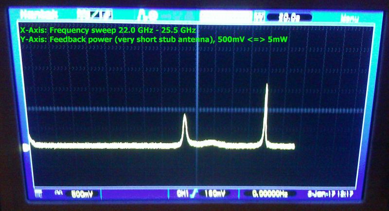
    Improvement in cavity resonance after simplifying the feed antenna:

    In the previous measurements I soldered a stub to the feed connector to reach lambda/4.
    In this configuration, this stub is missing. The feed pin is shorter than lambda/4 and its angle is the angle of the cone wall.
    There are only two peaks now, the first was also visible before, the second has a more narrow bandwidth and higher amplitude.

    Probably these peaks represent two different cavity excitement modes in this frequency range.

    We will track both of them in the next test session.

  • Cavity V5 measurements

    Paul Kocyla01/03/2017 at 21:19 5 comments

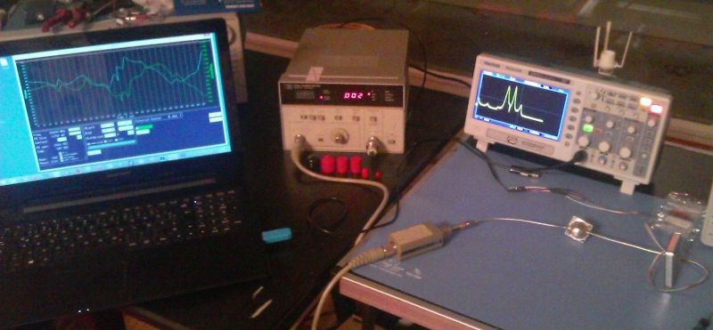
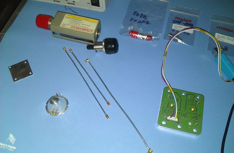
    Here is the setup:

    The EMDdrive V5 board is connected to the cavity´s feed antenna (lambda/4 stub).

    A shorted antenna is used as feedback port which is connected to a power sensor.

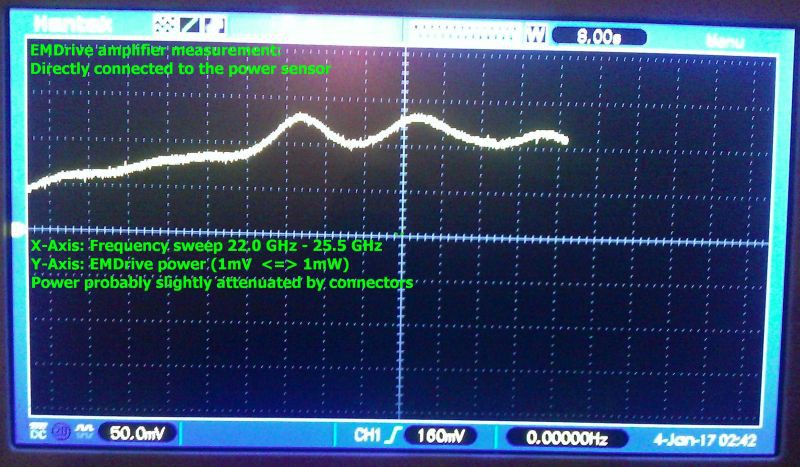
    First, I measured the amplifier´s performance by connecting it directly to the power sensor.
    Here are the results:

    At over 23.5 GHz the power is over 100mW - hmmmm it´s a 1000mW amplifier, so that´s not that good, the board is probably not perfectly designed, cables and connectors have losses. The sensor has a 20dB attenuator (compensated calculations for that) and a SMP to 2.92mm adapter, they will probably also cause some losses. So let´s say it´s around 150mW at the working frequency range.

    Now comes the interesting part: The feedback port is connected to the sensor, and frequency sweeps are performed. It´s basically a scalar network analysis.
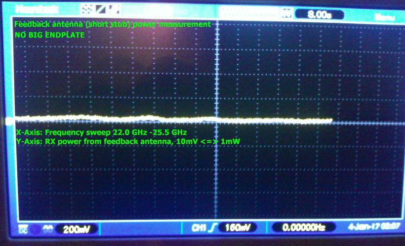
    First, I left the cavity opened - this means the big endplate was not connected.
    Here is the result - flat, almost no feedback. That´s not surprising, should be like this:

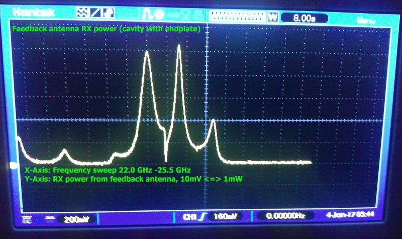
    Look what happens when the big endplate is attached:

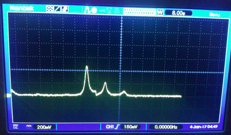
    We get three main peaks. Two strong and one weak - and some smaller artefacts.

    I assume the small disturbances are caused by the antennae destroying the optimal shape of the cavity.

    When you look at the power level, it seems that the feedback antenna is sucking all the power out off the cavity, not good, it was probably too long - but better starting off too long than too short. So I cut the feedback antenna shorter, from around 1.7 mm to 1mm (approximately). Here´s the result:

    That´s better. The feedback antenna now sucks 40mW instead of 100mW. That´s better, but still too much.

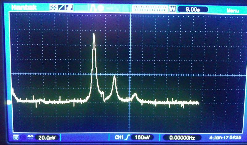
    Now I cut the antenna to the ground, it´s just a pin in the hole, but the result seems ok:

    Note that the V/div is now 20.0mV instead of 200mV, so it´s sucking just 10mW now.

    Probably some room for improvement here - let´s see, but that´s acceptable.

    BTW before the trolls cry again because of missing axis labels: The two last pictures have same labeling than the third last - I´m just too tired to insert them - have a newborn baby now and a full time job: X:FRQ sweep, Y: power 10mV <=> 1mW

  • EMDrive V5 and cavity prepared for testing

    Paul Kocyla01/02/2017 at 20:48 0 comments

    New EMDrive cavity and board prepared for measurements.
    A precise power sensor, cables (just assembled), adapters and attenuators are all rated for 26GHz.
    I will be able to tell soon exactly how much power the amp is delivering and will be able to measure the cavity properties and resonance condition.
    After these tests I will optimize the feed antenna for maximum power delivery. I will try dipole and loop.
    The cavity has two ports: One with the feed antenna at lambda/4 distance to the big plate and another with a short stub for feedback.

  • Equipment update

    Paul Kocyla12/22/2016 at 08:52 0 comments

    Kein automatischer Alternativtext verfügbar.

    New member in the lab family: A precision power measurement device.
    This device is capable of measung power qualitatively up to 26GHz.
    The funny thing is that although the design comes from 1975, it´ s still in use today and it still has its price. It´s the only thing you can buy to achieve the measuring precision for these frequencies which doesn´t have the price of a new familiy car - 40 years later. At the time of release it was different.
    Sensor head is the 8485a - was lucky to shot one on ebay for half the price they usually go.
    But now finally we get exact measurements for the EMDrive, which will help to optimize the overall design.
    The EMDrive itself will get its own power meter on board - in form of a small chip with less accuracy but good enough to do the job. But until then, this buddy will help to get qualitative results.

    The 26GHz equipment is quite expensive, for example a simple 2.92mm to SMP adapter costs over USD 70 - but it´s important to have the connectors and cables rated for the max. frequency, because in other cases the frequency response of the devices will have notches. Imperfections in the connectors lead to resonances and reflections inside the connectors, the connectors act like a weak cavity.

  • Cleaning up

    Paul Kocyla12/17/2016 at 18:54 0 comments

    The "Flying an EMDrive" project has been removed due to maintenance overhead.
    This doesn´t mean that the EMDrive will not fly - in fact we got a partnership which will make a launch available soon - stay tuned :)

    More details will come later - after we signed the contract

    The things changed a little bit now. We had a test session at TU Dresden with Prof. Tajmar and will establish a lasting partnership.

    The test results are not to be published yet due to an agreement, but what I can say is that the force was not high enough for a reasonable orbit test. The reasons were thermal issues in the high vacuum which caused the amplifier´s TX output power to degrade.
    I made a newdesign with a more efficient amp in an externall box which can be thermally cupled to the scale.

    Here´s the setup:

    I invested some of the funded money in a good used but affordable test equipment going up to 26GHz and will make a careful redesign for a next version V6.

    The paperwork for the satellite launch has been initiated, there´s a lot to do in 2017.

    I plan to do video blogging on the process. I am also expecting trolling as usual, so only constructive comments will be answered.

    The project page will be cleaned up as many of the first steps to get to the current state are not helpful anymore (learning fails).
    If you still need them then feel free to make a backup.

  • EMDrive V5

    Paul Kocyla11/27/2016 at 20:55 3 comments

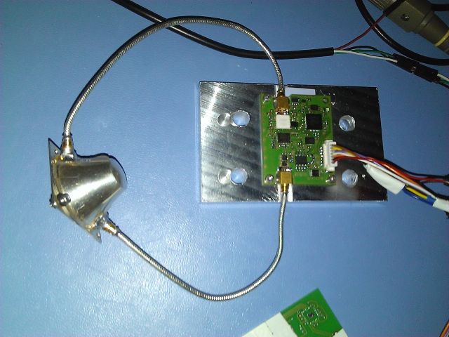
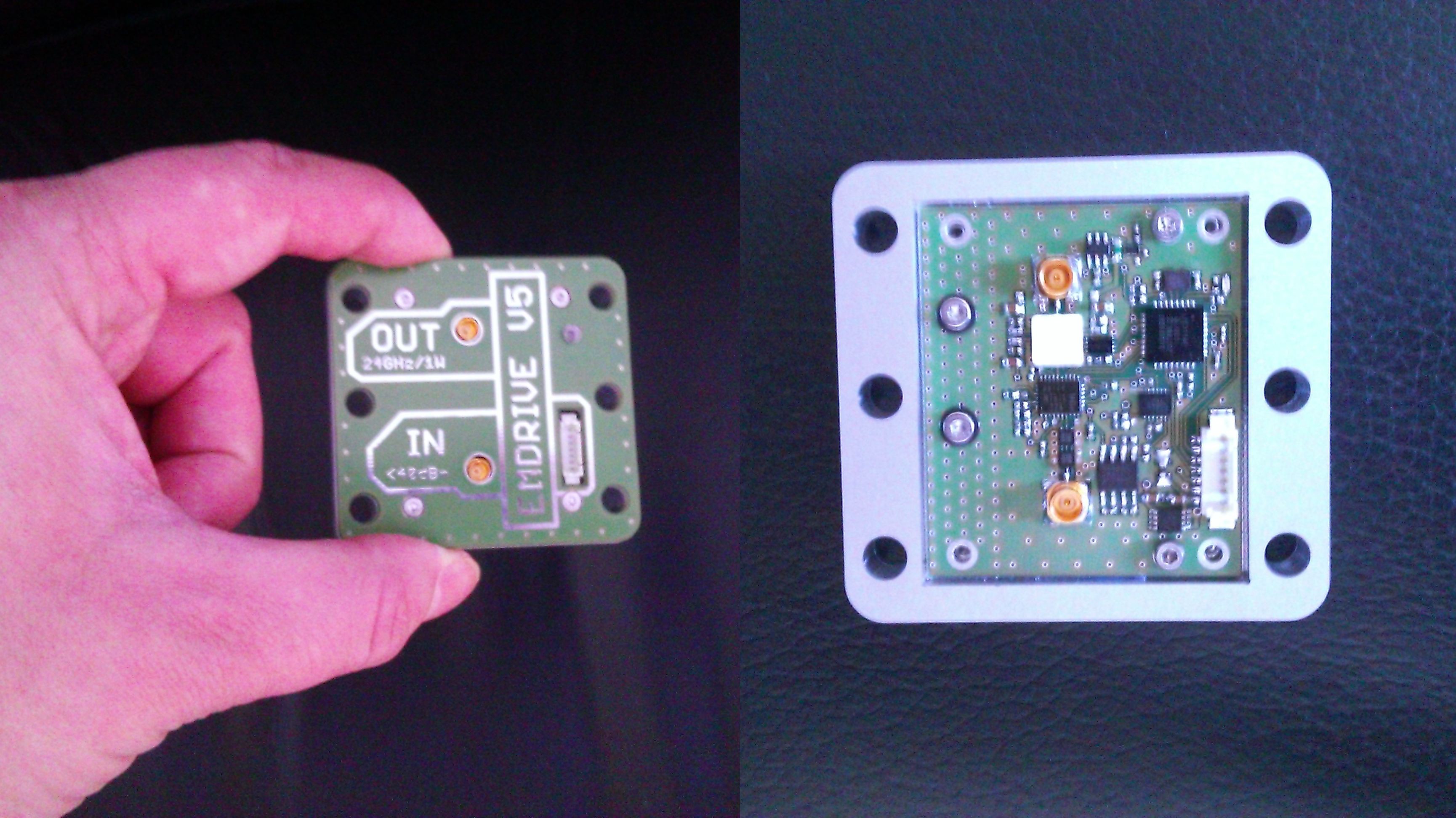
    The EMDrive V5 board is assembled.
    The metal box can be attached to the scale body for better heat dissipation as we had heat issues during the testing in Dresden. There is also a more efficient amplifier on board which can delliver twice the power than the version V3.
    Now waiting for the new silver cavity to come.

View all 83 project logs

Enjoy this project?

Share

Discussions

BART wrote 08/27/2015 at 16:35 point

Would putting the cavity at a partial vacuum allow the em waves to travel better and more efficiently?

If you used magnets at the top and bottom, that might create a plasma cavity internally to help guide the waves.

There's some work with using plasma waveguides with lasers.

  Are you sure? yes | no

Paul Kocyla wrote 08/27/2015 at 20:56 point

If I should get a Terrawatt laser in my hands some day, I´ll try this :-D
They write it´s to guide high energy laser beams by a plasma. Seems, it doesn´t have much to do with an EMdrive. interesting though, although I just took a short look and don´t understand all aspects of it. Thanx for the link, I´ll take some more time to read.

  Are you sure? yes | no

BART wrote 08/27/2015 at 21:13 point

Wouldn't we all want a terra watt laser. Lmao. 

The point of the links was to show the same idea being used in other fields, not the implementation. 

If the chamber is under vacuum and you're pumping high energy microwaves it'll be in a plasma anyways. This could actually hurt, but if you could use ring magnets at the top and bottom to direct the plasma to create a cavity.

A plasma container could/should have almost infinite q.

Wrong?

Thanks for your time and consideration. 

  Are you sure? yes | no

willemstaal wrote 08/31/2015 at 13:40 point

or a hydrogen maser in stead of a laser..

  Are you sure? yes | no

spork321 wrote 08/25/2015 at 20:45 point

Has there been thought of integrating something like a Koch island patch resonator in the cavity design to increase the q-value?

  Are you sure? yes | no

Paul Kocyla wrote 08/25/2015 at 21:18 point

A fractal cavity? Interesting idea. It would be great to have a simulation on that one. I learned that many people do simulations with the MEEP software. I didn´t try it yet - it would take long time for me o get inside it. We focus on building an actual proven design and try to get something which is above noise.
Maybe someone is interested in making a theoretical analysis of this idea? Would be exciting.

  Are you sure? yes | no

hobbesalpha1 wrote 08/25/2015 at 01:30 point

Go for contact with the piston if possible. I would almost say go for contact on all sides. However it might be hard to accomplish that with your current design.

  Are you sure? yes | no

hobbesalpha1 wrote 08/25/2015 at 01:32 point

Was going to perpose something like a bering design to the rim of the piston that way you could achieve the most contact with the piston, but also get the best non-fiction setup

  Are you sure? yes | no

Paul Kocyla wrote 08/27/2015 at 07:32 point

We´ll try a contact plate with a big threaded hole for a screw

  Are you sure? yes | no

Keegan Reilly wrote 08/23/2015 at 19:00 point

Have you considered using an interferometer setup to measure microscopic displacement?  Would that allow cleaner, more accurate measurement of the force than a load cell?  The first setup I thought of was placing the EMDrive on the end of a long thin pole.  Tiny force would create a very small displacement of the end of the pole.  

Another option would be your floating platform.  Imagine floating the EMDrive on a few air-filled drinking straws, like an oil rig.  Might need a weight at the bottom for balance.  Back of the envelope calculation:

If the straws have cross-sectional area of 1 cm^2, and you can measure their vertical displacement with the interferometer to within 10 nm, then that equates to 1 microgram of water being displaced.  1 microgram in earth gravity is 9.807 nano-Newtons of force.  

With some extra work, you could take advantage of additive force as well.  This floating system would tend to oscillate vertically at some natural frequency (0.1-1 Hz, rough guess, depending on weight of platform), like a boat.  If you pulsed the EMDrive at the same frequency, then the displacement would be additive, much like your rotating platform.  

Using an interferometer may have other advantages as well, the laser light wouldn't suffer any electrical interference from the EMDrive itself, so could be a cleaner signal.  One complication would be if the laser light photons actually put pressure on the platform.  I have no idea how to calculate whether that would be a concern at these scales or not.  Another complication is floating this thing in water makes vacuum testing it really hard.  You'd have to float the whole vacuum chamber.  It'd be doable, but a pain.  

I'm just brainstorming with you, just in case the load cell doesn't give you nice enough data.  Nice work so far and best of luck with the rest of it!

  Are you sure? yes | no

Paul Kocyla wrote 08/23/2015 at 19:47 point

Thanx for your ideas, they are great. We made floating tests before. The problem were tiny forces coming from the electrical wires to the RF source interacting with the magnets under the water tank which kept the platform of drifting away to the walls of the tank. Even 30mA were enough to displace the platform into one direction, regardless the orientation of the EMdrive. Other electrical sources in the house caused unpredictable displacements as well so we could only get implication of thrust rather than a proof.
But the floating platform is very promising.

The load cell seems to loose its accuracy in the milligram range.

I did the board anyway in case we can figure out how to make it more accurate.

The interferrometry sounds interesting. I´ll need to study that technique as I never used it before.

  Are you sure? yes | no

Keegan Reilly wrote 08/23/2015 at 22:02 point

Yeah, I've never used interferometry for measurements myself either.  I've made holograms though, which is essentially the same thing.  Various homemade designs have shown up on Hackaday though, those should give a nice starting point:  http://hackaday.com/?s=interferometer

The equipment required is pretty minimal, a laser pointer, prism, mirror, and camera.  And some video processing software (I believe there are open source packages, I'd have to search around for a bit).  It can definitely be done.  The 10nm accuracy is a rough guess.  Wikipedia says state of the art systems get down to 1nm accuracy.  Worst case would be 700nm for a red laser, 400nm for blue, since that's one whole wavelength.  Even if your camera could only distinguish two images (perfect interference, and shifted by 1/2 wavelength), that gets you down to 200-350nm resolution, or about 20-35 micrograms (I think).  Not sure how that compares to your load cell, it sounds pretty good, but the laser would hopefully be less prone to noise from electrical interference.  

That said, interferometers are touchy things too, since they are so ridiculously sensitive.  Just to give you an idea, our holograms had to be made in a sealed, unmanned basement, since the air disturbance of us breathing would mess up the interference pattern.  We had to set it all up, then let the room air settle for an hour, then remotely trigger the exposure.  We could easily pick up large trucks driving about a block away despite having vibration dampened tables (they weren't as nice as lab-grade air bearing tables though).  

That's amazing that the RF supply lines were interacting with your submerged magnets!  Pretty wild how accurate you guys are getting with this stuff.  The other advantage to measuring vertical displacement is that you could actually anchor the platform to the side wall with a couple knife edge lever arms.  They just need to swing vertically with no resistance, but they could help limit the horizontal floating around, without any magnets involved they shouldn't interfere too much. 

Another consideration is making the two laser paths as close to identical as possible.  This will minimize errors due to air currents/temperature/density changes and external vibrations.  You might even have two floating mirrored platforms next to each other, one with a dummy microwave load and the other with the real EmDrive.  The interferometer will only show differences in the laser path length to each platform.  If they are indistinguishable except for the shape of the cavity on the EmDrive, then that should really help isolate the force due to the drive itself.  

There may be other better ways than a floating platform, I'll do more brainstorming.  Hanging the EmDrive from a string like a pendulum might be easier.  Let me know if I can be of any help if you decide to try the interferometer thing, good luck!

  Are you sure? yes | no

Keegan Reilly wrote 08/23/2015 at 23:23 point

Another back of the envelope calculation for a pendulum setup.  If the EmDrive weighed about 100 grams, and hung on a 1 meter string, 1 nanometer displacement should equate to 1 nano-Newtons of restoring force being counteracted by the drive.  That should give you really nice accuracy, if I did my math right, haha.  

  Are you sure? yes | no

Paul Kocyla wrote 08/24/2015 at 21:23 point

I checked the link you sent me of the simple interferometer. That´s amazing! Thanx you so much. I ordered the parts, we are going to try this method. The load cell approach will not do it - at least I got an USB milligram scale now, which would be damn expensive when having to buy it :-D

  Are you sure? yes | no

Conundrum wrote 08/22/2015 at 07:55 point

@movax This was more brainstorming.

The existence of a material with Tc of >164K even in such extreme conditions suggests that other hydrogenated materials (ie Pd:H3S) might superconduct at slightly less than 203K but maybe more as they are a more rigid lattice.

Its also worth noting that my earlier research shortly after Prof.Pablo published his work on apparent RTS in graphite suggested that under certain conditions there might be a way to dope graphene with heavy metals such as lead (Pb) and in fact later work by other scientists proved that the electrons behaved anomalously under this case.

It might be possible to make it work with cuprates as well and a lot of research has been done to increase Tc here.

Eck has suggested using high dielectric constants to increase Tc and has promising results though a very small UF.

  Are you sure? yes | no

Conundrum wrote 08/22/2015 at 05:22 point

Hi, if you're interested I have some parts here (namely 24GHz Gunnplexers).

I also have some ideas to make a superconducting cavity in a similar way to your Shapeways one, however this time coating YBCO inside the cavity.

There are better superconductors now, one focus of my research is making new materials that work at nearly room temperature which is seeming more and more likely after the 203K H3S@1.5M atm result reported from Max Planck.

  Are you sure? yes | no

Paul Kocyla wrote 08/22/2015 at 06:58 point

I read recenty abut these new superconductors. But it sounds quite impossible to get this material. If you´re able to get or produce it - good luck, this would be incredible. So are you brainstorming now or do you have access to this equipment? 1,5Matm is very much - there are not many devices like that on earth.

According the RF sources: I just soldered our new tuneable source, capable of delivering a few hundred milliwatts. It´s tuneble over a wide range so we hope to tune into resonance. There are new integrated ICs on the market making it easier to build one, so thanx for the offer, but we have already what we need.
We will post the STLs for our cavity if you want to produce one.

  Are you sure? yes | no

hormelbob wrote 08/20/2015 at 20:06 point

I don't fully understood why that platform is floating in one of your previous posts... magnets on either end or is the drive itself achieving lift?

  Are you sure? yes | no

Paul Kocyla wrote 08/21/2015 at 19:57 point

The floating is achieved by a digitally controlled electromagnet.
The purpose of letting the platform float is to reduce friction for beeing able to measure tiny forces. The EMdrive forces are - if they occur - very very small, especially for the Baby EMdrive, so a rotatiion or lift could not be achieved by the drive alone.
For our next test we will use direct thrust measurement by digitally oversampling a load-cell voltage.

  Are you sure? yes | no

hormelbob wrote 08/26/2015 at 21:33 point

Thanks for the reply, I am really excited to see your upcoming test runs. As I understand it, you have not actually fully assembled the drive as of yet- assuming I'm not mistaken, do you have a timeline for actual tests for this device?

  Are you sure? yes | no

Paul Kocyla wrote 08/27/2015 at 05:48 point

The new assembly is still in progress. I hope to finish the interferometry setup next week.  If no problems occur with the new RF board, it will also be ready next week.
The cavity assembly is almost finished except the small endplate cap. We want a better conductivity, so we need a new endplate.
So I hope we will be able to deliver first results in about 3 weeks.

  Are you sure? yes | no

hormelbob wrote 08/28/2015 at 00:44 point

Thanks for the update and explanation, I greatly look forward to seeing your test results (not that I will understand everything). It is inspiring and exciting to see experiments like this in real time and by the hands of everyday engineers interested in sharing their results for analysis, replication and discussion with everyone. It is disheartening to think how may projects there must be locked away behind militaristic or industrial curtains of secrecy that will never see the light of day. Good luck and good work so far!

  Are you sure? yes | no

Paul Kocyla wrote 08/18/2015 at 19:00 point

Grzegorz Maj posted this on youtube. Could this be a simple explanation of how the EMdrive works?
That´s great - add one dimension :)
A 3 dimensional wave system acting on a 2D cavity -> A 4 dimensional wave system acting on a 3D cavity

  Are you sure? yes | no

hobbesalpha1 wrote 08/15/2015 at 01:05 point

Sorry, wrote the wrong email to my last account. Keep forgetting that it isn't @google.com bit actually @gmail.com anyway. Cool, please do tell me about the trials with the silver and also how the non conductive coat test goes as I think everyone is overlooking a possible and powerful explication as to how the emdrives work. If I am correct then you might actually see an increase of force.

  Are you sure? yes | no

Paul Kocyla wrote 08/15/2015 at 07:25 point

Ok. We´ll post all results in the project log and share the raw data in the repository.
We will start with basic experiments first and see if we get any measurable thrust. If we do, we´ll continue with nonconductive dielectrics.

  Are you sure? yes | no

hobbesalpha1 wrote 08/14/2015 at 20:13 point

Hello, I have an experiment I would like to suggest, coating the endplate with a non conductive skin on the outside. It is just something I have always wondered with the emdrives, as if you go by NASA'S tests, the drive made less force in a vacuum then it did in air. Always wanted to know why the disgrephency.

  Are you sure? yes | no

Paul Kocyla wrote 08/14/2015 at 22:41 point

Idea 1: There was a thermal effect associated with air

Idea2: A dielectric slows down the wave speed which may result in lower force on the desired endplate -> higher net force

Idea3: eg some molceules resonate at certain frequencies (like water near 2.4 GHz -> microwave oven or ammonia at 24GHz)

Unfortunately I am just keen as EE and CS, but trying to learn new stuff... also needed for the EMdrive

The nonconductive dielectric on one side is a good point, thanx for that. If our experiments work we will also check out the dielectrics.


  Are you sure? yes | no

flux_capacitor wrote 08/15/2015 at 18:23 point

Idea4: Copper oxidized inside of the cavity and Q collapsed, hence thrust decreased, between ambient air and vacuum tests (like Tajmar's experiments).

Idea5: The speed of light in vacuum is not the same as in air, so if you properly tune the length between plates to achieve full resonance in ambient air, and let this setting untouched afterwards, the cavity could not be as resonant in a vacuum. Thus less thrust.

Idea6: Shawyer's conjecture of "motor" and "generator" modes: the EmDrive will not register a significant acceleration unless initially motivated to do so by mechanical vibrations (of unspecified magnitude and frequency) to produce initial acceleration in the direction pointing from the big base to the small base. If this conjecture is valid, the reason why much lower thrust is measured in vacuum is because the EmDrive had no vibration to trigger such initial condition.

  Are you sure? yes | no

Paul Kocyla wrote 08/16/2015 at 09:13 point

Good hypotheses.

  Are you sure? yes | no

Alan S wrote 07/29/2015 at 20:27 point

The experiment I'd like to see involves a nicely-leveled air hockey table.

The widget you've shown looks like it could be completely "sealed" into what's effectively a large "Air Hockey Puck". 

An air hockey table (for those that don't know) has a zillion little holes with air coming out, so the pucks are effectively little hovercars. Friction: Exceedingly low. Lower than all the discussions of linear motion I've seen proposed to date. 

The default 'came with the table' source of air will need to be boosted to overcome the weight of the device. Then a short set of experiments to show that any movement is not just Brownian motion. ... Then add a servo to aim the cavity for steering. :D

  Are you sure? yes | no

Paul Kocyla wrote 07/30/2015 at 19:33 point

Funny, i thought of that too. But the air disturbations are larger than the expected force of the drive. Should the force reach the millinewton range, I´ll think about it :)

  Are you sure? yes | no

Alan S wrote 07/30/2015 at 21:47 point

Mock me: I missed the magnetic bearing. :D

(Started from the bell-jar demonstration video, assumed it was hanging, my bad. )


I love that your device is small. The 'onboard power and emitter' is a gigantic plus, even as it comes with 'lower power'.

This enables "Totally sealed device" and "EM Shielded device" (as you move from remote control to onboard micro). Both seem like they're going to be necessary in the end. 

  Are you sure? yes | no

Paul Kocyla wrote 07/31/2015 at 06:00 point

Yes. In a few weeks we want to have a multimode version ready with tuneable frequency and flexible antenna- and endplate position.
If we get measurable thrust with that we´ll produce a flight version to be put into a cubesat.

  Are you sure? yes | no

Paul Kocyla wrote 07/26/2015 at 13:35 point

Working prototype or it didn´t happen. There´s so much of this stuff on the internet and it´s becoming more and more.

Most of it is esoterical stuff which is blocking working prototypes from becoming seen and it´s hard to filter out what´s real or what´s fake, what´s an ongoing research and what´s just esoterical noise.

I´ll invest time into making the EMdrive work. I am open to another ideas too and willing to try them out, but I am very sceptical in the first place.

  Are you sure? yes | no

Boz wrote 07/22/2015 at 22:19 point

Link to yesterdays spaceshow podcast with the physisist Jim Woodward regarding the Mach effect which is a similar propellent less drive and some mention of EM drive which may be relevant/useful to this group... http://www.gigadial.net/public/station/11253

  Are you sure? yes | no

phil.wilson48 wrote 06/19/2015 at 03:39 point

At 40mW (0.04W) power input, the Baby EMDrive thrust is at best 5uN (assuming Q of 25,000) or 0.0005g. SnowFlake weights 0.003g or 6x more. Even EagleWorks could not measure such a small thrust.

  Are you sure? yes | no

barnettb02 wrote 06/26/2015 at 20:35 point

EMDrive in a computer or lap top.

  Are you sure? yes | no

Paul Kocyla wrote 07/08/2015 at 07:49 point

True. But the experiments will help to develop a better measuring system for future design. I designed a new tuneable RF source, and we will make the cavity tuneable. Let´s see if we get better results.

  Are you sure? yes | no

Jerichobarr wrote 06/14/2015 at 21:06 point

Keep up the good work!

  Are you sure? yes | no

Kevin Loch wrote 06/11/2015 at 21:18 point

Which end of the resonator is pointing forward in your "prograde" measurements?  The large end of the cone or the small end?    In the youtube video it looks like the large end is leading.

  Are you sure? yes | no

[deleted]

[this comment has been deleted]

Kevin Loch wrote 06/15/2015 at 17:02 point

Can you confirm which direction the emdrive was oriented (large diameter or small diameter leading) in your prograde and retrograde tests?  Different models predict a different direction of the force for an empty emdrive with no dielectric inserts, so it would be very helpful to know in which direction you measured the force.

  Are you sure? yes | no

Dejan Corovic wrote 06/11/2015 at 10:38 point

This type of propulsion was proposed by many other scientist, notable one was Andrei Sakharov. As well, prof. Dr. John Branderburg from US.

But why be satisfied with a mock up, when you can check the real thing. Please check this thread and download the included .PDF:

http://www.overunity.com/15514/disappointingly-practical-and-simple-em-propulsion-with-off-the-shelf-parts/#.VXlkPkYeqgR

  Are you sure? yes | no

flux_capacitor wrote 06/12/2015 at 22:40 point

Complete handwaving verbiage. Please cite ONE paper where A. D. Sakharov talked about anything similar to EmDrive or gravity-induced by Poynting vector. There are simply none. I give you a clue, start your homework from there: 

http://www.amazon.com/D-Sakharov-Collected-Scientific-Works/dp/0824717147 

And bringing together that prestigious Russian scientist with the guy who recently asserted Mars' civilization nuked itself long ago? Bleh. Besides his "work" has nothing in common with Shawyer's!

As for the rest, please stop spreading bullshit here, where others try hard doing real science. The conspiracies sites and documents you presented are anything but science.

As per Pauli: You're not even wrong, sir.

  Are you sure? yes | no

Paul Kocyla wrote 06/14/2015 at 19:48 point

That´s the problem. Anything science fiction-like is beeing pushed on the internet in a religious way. Most is bullshit, but there are some pears in between. Luckily, the EMdrive made it, because the Chinese decided to build it officially in an university project.
Maybe some other great ideas didn´t have this privilege.
It´s verx important that independent people do research, no matter if they have millions of dollars or just a few tools in the garage. Universities are really really afraid of loosing reputation, so they usually stay away of projects like this.

  Are you sure? yes | no

euan.french wrote 06/10/2015 at 22:12 point

Hi. I'm an A2 level student looking to build an EMD for my Extended Project Qualification. You can reach me at euan.french@ntlworld.com . I'm looking for more information on how you constructed the EMD, especially relevant equations and how to find the resonant frequency. It would mean a lot to me if you could help, and hopefully as almost-colleagues we can bring this technology forward another step.

  Are you sure? yes | no

Paul Kocyla wrote 06/14/2015 at 19:52 point

We provide what we manage to provide between daytime job and family life.
We do it in our free time.

  Are you sure? yes | no

euan.french wrote 06/15/2015 at 07:31 point

That's fine, I'm not asking you to take this up as a full time research project (I can't either as it runs alongside my school time) but I really need some guidance in how you set your thruster up specifically finding things like the resonant frequency.

Cheers.

  Are you sure? yes | no

Crypto [Neo] wrote 06/10/2015 at 20:40 point

Concerning the rotation rate measurements what's the main sources of noise for the tests?

  Are you sure? yes | no

Paul Kocyla wrote 08/16/2015 at 20:46 point

I think lorentz forces and air resistance would cause the major disturbance.

  Are you sure? yes | no

Similar Projects

Does this project spark your interest?

Become a member to follow this project and never miss any updates