Paul Kocyla
-
PCB for new RF source
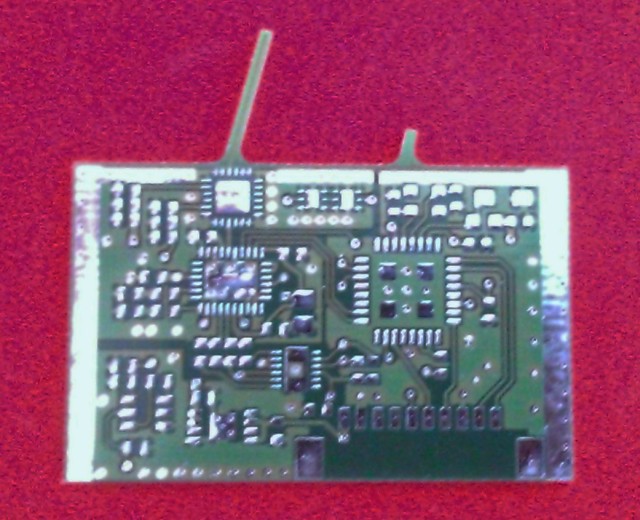
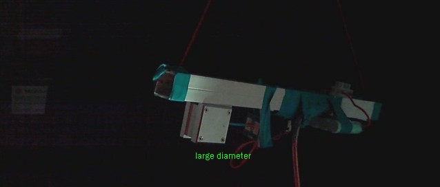
07/17/2015 at 11:39 • 0 commentsIt arrived. The PCB has two antennas. The big one is the probe for feeding the cavity and the small one is for feedback RX.
We will try to make the antenna position variable inside the cavity.
About the RF source: A VCO transceiver is controlled with a 16bit DACs The TX frequency is divided by 16*65536 and fed back to the controller. The I component of the RX baseband is fed into the ADC input of the controller.
A 500mW amplifier is connected to the transceiver´s RF output and fed with 5V. A negative bias for the amplifier is generated by a charge pump from another DAC.
The feedback antenna is shortened for not stealing much energy out of the cavity. It is attenuated by 40dB before going back to the transceiver IC.
![]()
-
Redesign
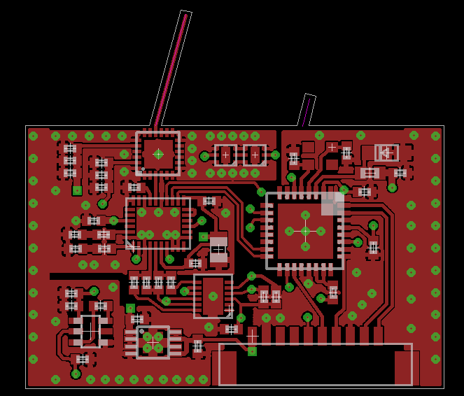
07/08/2015 at 07:35 • 0 commentsThe current RF source prototype is too shabby, so it´s time to redesign.
I designed a board for generating a digitally fine tuneable RF source in the 24GHz band capable of delivering 500mW of power. It also contains a feedback antenna.
I´ll stop the current testing procedures now and will send the cavity to Jo for modification.
The cavity will be also made mechanically tuneable. Together with the fine frequency tuning we hope to get better results in the future.
I will use the LightBlue Bean we won recently to communitate with the platform remotely:
http://store.hackaday.com/products/lightblue-bean![]()
-
Trouble with sideeffects
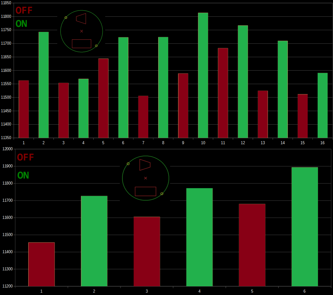
07/07/2015 at 16:40 • 5 commentsI ran two clean tests with cavity mounted CW and CCW.
What looks like thrust on the first sight turns out to be a parasitic force that turns the platform always in the same direction :(
So it must be some current or thermal effect in the system. My guess are lorentz forces.
I don´t know how to get rid of this effect, it will make measurements really hard.
I could compare the differences between the ON/OFF phases of the two tests to get some clues, but because the baseline is always fluctuating it´s hard to see.
And the baseline also changes when the cavity is turned around due to the different mass distribution on the platform (magnet gets realigned a little and causes slight position change?)
Do you have any suggestions?
X-Axis: on/off phases, ca. 30min each
Y-Axis: platform angle in 1/100°
Means of the first graph: 11563 11743 11554 11569 11644 11723 11506 11724 11589 11814 11683 11767 11525 11710 11512 11591
and of the second graph: 11456 11727 11605 11772 11680 11894
![]()
-
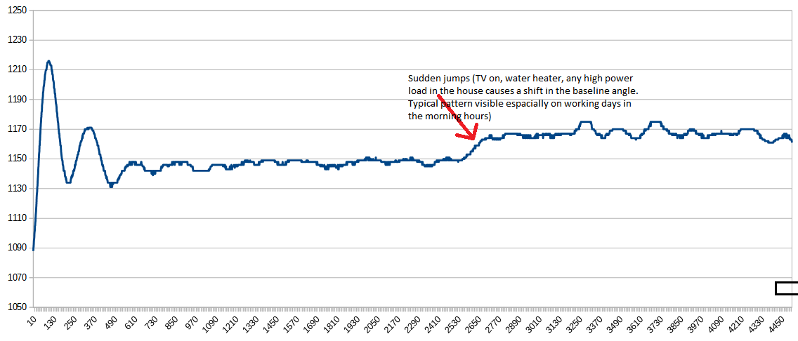
Preliminary Tests (swimming platform)
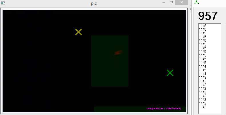
07/05/2015 at 13:35 • 8 commentsOptical markers (LEDs) are tracked with a camera to determine the angle of the platform.
![]()
It shows that the platform reacts very sensitive to high power loads in the house. When the TV is on, it gets noisy. When people take shower in the morning hours (electric heating here), the angle lowers significantly. Where the jump in the pic below comes from - I don´t know, maybe a neighbor toggled some power load.
For the preliminary test, I took the data from the flat areas of the graph - in this case in the sections before and after the jump.![]()
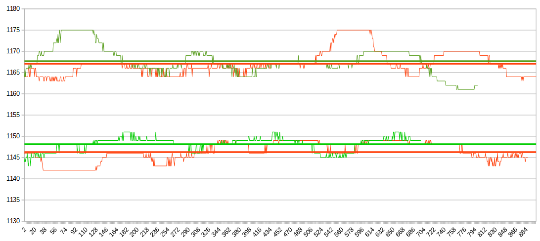
The cavity has been turned on and off alternately. For the preliminary tests, two ON and two OFF phases were recorded with cavity in CW and CCW direction. Green graphs show cavity OFF, red graphs show cavity ON. Due to the jump (see above), the second pair of values is raised.
Cavity attached to push CCW:
When the cavity is on, the angle drops below the off-level.
![]()
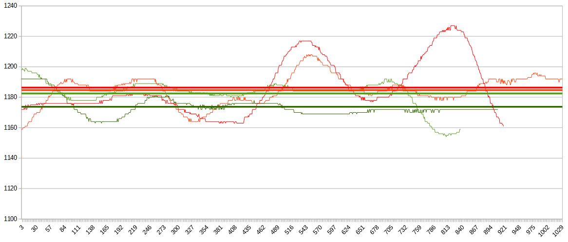
Second test with cavity meant to push CW:
The angle rises above the off-level.
![]()
This looks plausible so far. Anyway this is neither a proof nor a real valuable data.
Another think I noticed is the poor resolution in determining the angle.
It´s because the marker detection algorithm works only on pixel accuracy. I will improve it to calculate the marker position on subpixel accuracy.
Although I am happy to see these results, it might be just a coincidence that they look good. I´ll need to perform long duration tests to be sure.
-
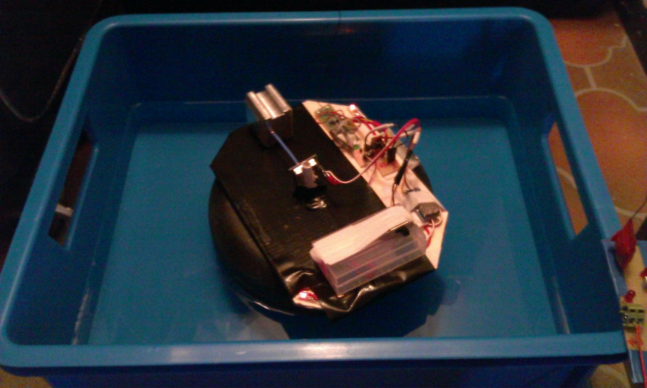
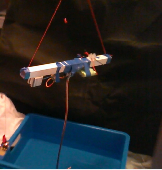
Swimming Platform
07/03/2015 at 09:32 • 0 commentsHere´s the new swimming platform.
We hope this one will give more useful results.The platform is stabilized by two cuboid neodymium magnets, one under the platform and one under the water tank. The magnets keep the platform aligned in the center of the water tank while the cuboid shape works like a weak torsion spring, aligning the rotation angle to a defined state.
The data acquisition will be made automatically via optical tracking of two LEDs mounted in the edges of the platform.
Many thanks for your comments and suggestions - we hope to provide some results for you soon.
![]()
-
Further steps
06/19/2015 at 11:40 • 15 commentsThe magnetic levitation rig is not forgotten:
We will build a new levitator from scratch, with a strong electromagnet, an analog feedback loop for stability and a precise platform.
It will be designed that it can fit into our small vacuum chamber.
But this will take much time, so in the meantime we will perform experiments with a swimming platform.
The first results will be available probably next week.
Further in the future, the oscillator will be replaced by a custom build with 500mW
-
Torsion Test 4 (inversed)
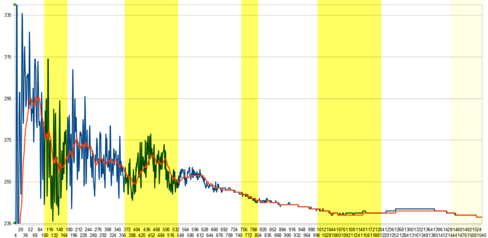
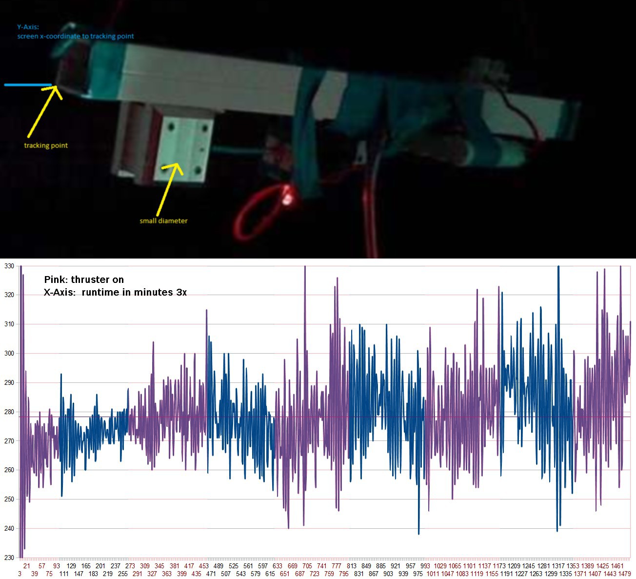
06/18/2015 at 11:01 • 22 commentsRaw data here: https://www.dropbox.com/s/rjsaq4jvy75vgmm/data_torsion3_inverse.txt?dl=0
Video here: http://youtu.be/CqT7TW0TZoc
Setup is like torsion test 3, but with cavity inverted and damping increased (more area on the fin in the water).
Goocy proposed to randomize the on/off times for better t-test analysis
Yellow <-> thruster on. Battery got weak after the last on-phase
On-times:
97..174, 362..538, 747..803, 998-1208 (weak batt. until 1260), 1437-1541 (weak batt.)
Blue curve: raw data
Red curve: low pass filtered data (lowpass seems to be set too low, comes too late)
Interpretation is difficult for me - torsion 3 test looked very non-ambiguous compared to this one.
Maybe you can find anything useful in this data.
![]()
![]()
-
Torsion Test 3 (8 hours)
06/16/2015 at 08:58 • 10 commentsRaw data is here: https://www.dropbox.com/s/0xc07zznumvyvnf/data_torsion3.txt?dl=0
Video:
Cavity direction is inversed compared to the last test.
I put another battery pack on the rig, so I will run another test today with the same configuration but will invert the direction of the cavity.
![]()
![]()
-
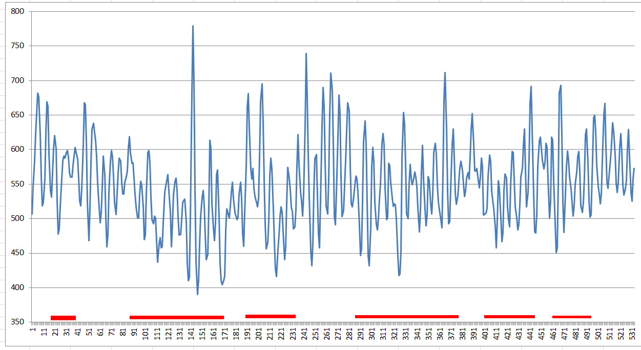
Torsion Test 2 - Data
06/14/2015 at 09:44 • 6 commentsNote: Battery got weak in the end of the experiment, but the trend is still visible.
I should have also make the on/off phases longer and homogenious, sorry for that. I couldn´t guard the experiment all the time so i came from time to time and toggled the thruster.
But after a test is before a test - new one to come.
Now that a trend is visible, I´ll prepare a better test.
X Axis: frame number (533 frames for complete video)
Y Axis: x coordinate of testrig edge (lower <-> rotated clockwise)
Data for download:
https://www.dropbox.com/s/jjmg8qa44q250z7/data_torsion2.txt?dl=0
Due to questions - Thruster was active for following data positions:
18..39, 87..170, 189..233, 285..376, 400..443, 460..494
Video file:
![]()
-
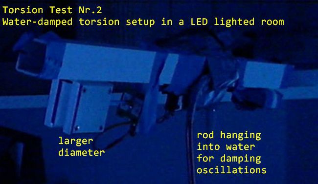
Torsion Test 2 - water damping
06/14/2015 at 05:20 • 6 commentsPerformed a second torsion test yesterday, this time with water damping to prevent oscillations.
A rod - bended on the lower end - is hanging into a water tank.
Unfortunately I wrecked my measurement notebook with some water from this setup, so it will take a while to either dry it and hoping it will work again or reinstalling the video software and some openCV tools on another computer to get the data out of the video (at least the timelapsed video is saved on USB-stick).Data is coming soon :)
Here´s a preliminary picture of the setup:
![]()