Close
0%
0%

TheSixthSense

Develop an extra sense for a better orientation.

Similar projects worth following
This project aims to provide users an additional sense, comparable to that of a bird. The Sixth Sense!
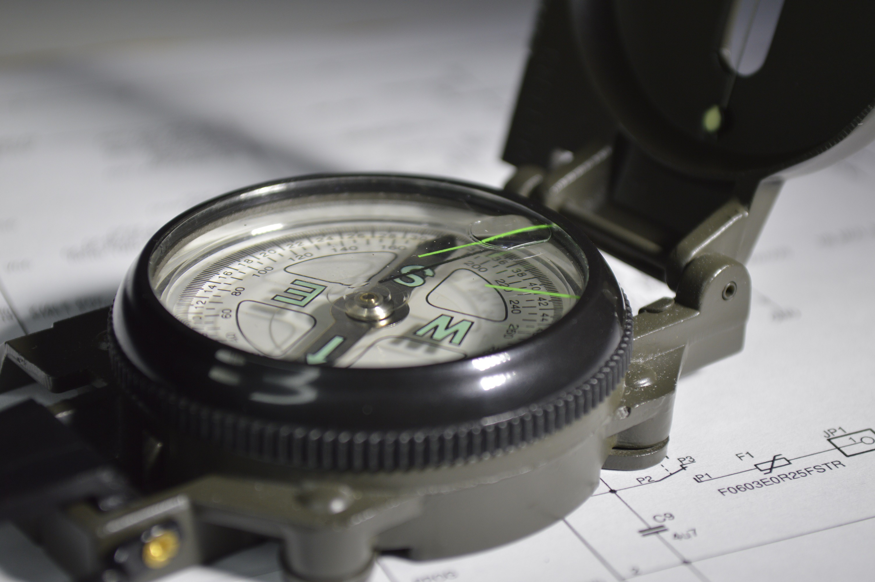
Birds feel the magnetic earth field and have a better orientation over long distances.
It’s part of their nature and necessary in order to reach warmer regions every winter. But why would you need this gadget?

The initial idea originated at the University Osnabrück, Germany. Vibration motors were mounted onto a belt and activated to point to the geological north-pole. The belt was very heavy but the idea was rather interesting. (see link below)

I decided to make my father a self-made birthday present. He has a balance disorder ever since he traveled in an airplane while having a cold. Right after the journey he felt dizzy for months and as it turned out his right inner ear was damaged. His general practitioner told him his brain had to be trained, so it can work with only one healthy inner ear. Okay, if it works this way, what will happen if we add this inconspicuous extra compass sense?

How to build (short):

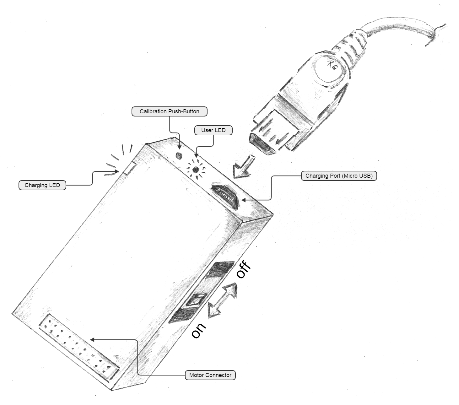
I created a small two layer PCB with a few components:

  • µC (Atmel ATXMega32E5)
  • 6 D Accelerometer and Magnetometer IC (STM LSM303D)
  • LiPo Charger (Microchip MCP73831T-2DCI/OT)
  • 2,5 V LDO (Microchip MCP1700T-2502E/TT)
  • MOSFETs for motor driving

I ordered the PCB from OSHpark and a stencil from OSHStencil for a few bucks. The dc vibration motors were delivered from china but unfortunately the company only had 5 in stock.

The programming was done in Atmel Studio 6.2 and a PDI-Programmer. I use the Atmel Software Library (ASF), which saves time since I don't need to write I2C drivers. After a couple of hours the first prototype was ready to use.

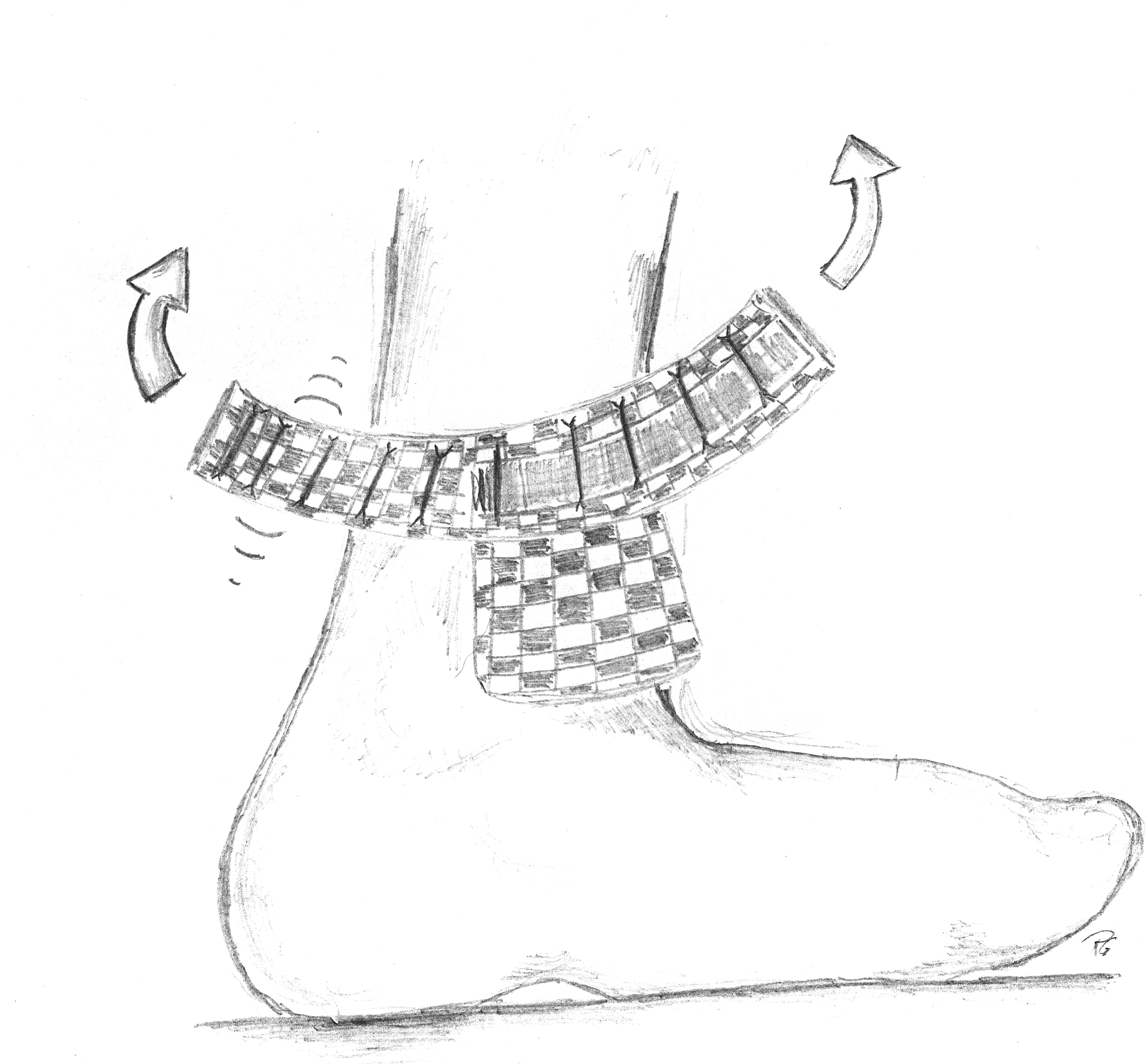
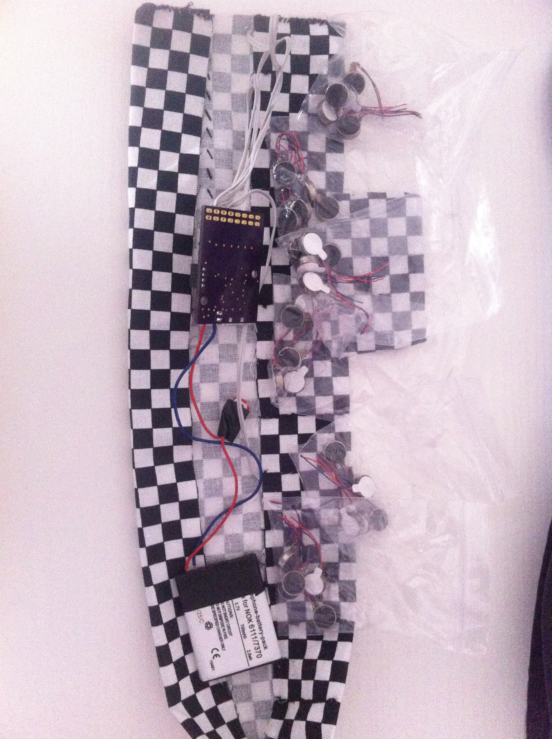
The device itself is mounted on a 100%-Cotton ankle strap, made by my girlfriend.

How it works (at the moment):

After the calibration phase, the program is ready for the magnetometer readings. Push the small button and just turn the PCB around the different axis. Push the button again and the calibration data is written to the eeprom section.

The accelerometer is used to make a tilt compensated compass. This way the exact position of the PCB on the anklet doesn't matter too much.

However, the inconstant movement speed of the foot is a problem. When you walk the ground vector is moving with the acceleration of your feed. Since the acceleration is raising and falling in one step an additional filter is required to determine the true ground vector.

Once the magnetometer output is read, the two vectors can be used to calculate the angle to the magnetic north (Calculation is not part of the introduction yet).

Afterwards the correct motors are activated and set to the desired intensity. For my first test I used four motors. As it turns out 4 motors don't work well enough when it comes to exact positioning. The shin isn't sensitive enough to detect the small differences between two vibration sources. The solution for my second prototype is to use eight motors.

The actual sequence is: Read one second data and filter, afterwards regulate the correct motors for 300 ms.

At the time TheSixthSense works well and it is rather comfortable. I have been wearing it for 3 days during my time in the office and nobody could hear the vibration. Nevertheless, in a noise free environment, it is loud enough to be heard by other people in the same room. It can be easily washed since all of the electronic parts can be taken out of the belt. The fully charged 700 mAh LiPo battery delivers energy for about 30 hours. Enough energy to last the gadget for approximately three days, while active.

Useful for:

  • blind people
  • people with a lack of orientation
  • cloudy days (because it's harder to know cardinal direction without sun and time)
  • hackers

TO-DO-List:

  • improve the filter
  • test adaptive vibration time → leg is not moving, lesser vibration interval
  • add bluetooth low enery functionality
  • make a proper case for the PCB and the battery

Challenges I would like to pass:

  • doing a hike in the woods in a region I don't know
  • coming out of a new york city subway station and knowing how I can get from 34th street to the 35th without walking to the nearest sign and noticing I went the wrong way

Challenges I wouldn't prefer:

  • introduce the security man at the airport scanner about TheSixthSense, because you forget to take off the anklet
  • getting kidnapped and blindfolded,...
Read more »

  • 1 × Li-ion 3.7 V 870 mAh 3.2Wh for Nokia 2600 classic
  • 8 × Mini vibration motor 2.0mm SKU: 316040001 (seeed studio)
  • 1 × 28 AWG Ribbon .050 Zip 16 Cond Mouser Part Number: 523-191-2801-116FT

  • TheSixthSense as a gift

    Sebastian Foerster07/23/2016 at 10:29 0 comments

    There are no real engineering new's on this project.

    But I wrote a organisation for blind people to find a person who could wear this anklet and give me some test feedback.

    So, I gifted my anklet away...

    The results are: While he was walking he has to concentrate on his blindman's stick and couldn't "read" the information from the anklet at the same time. But he managed this with short stops to get the compass information. He find this additional information really interesting.

    It feels good to help people in there difficult situations!

  • artist's rendition​

    Sebastian Foerster09/20/2015 at 18:41 0 comments

    Thanks to my buddy Robby I can present an artist's rendition of the sixth sense.

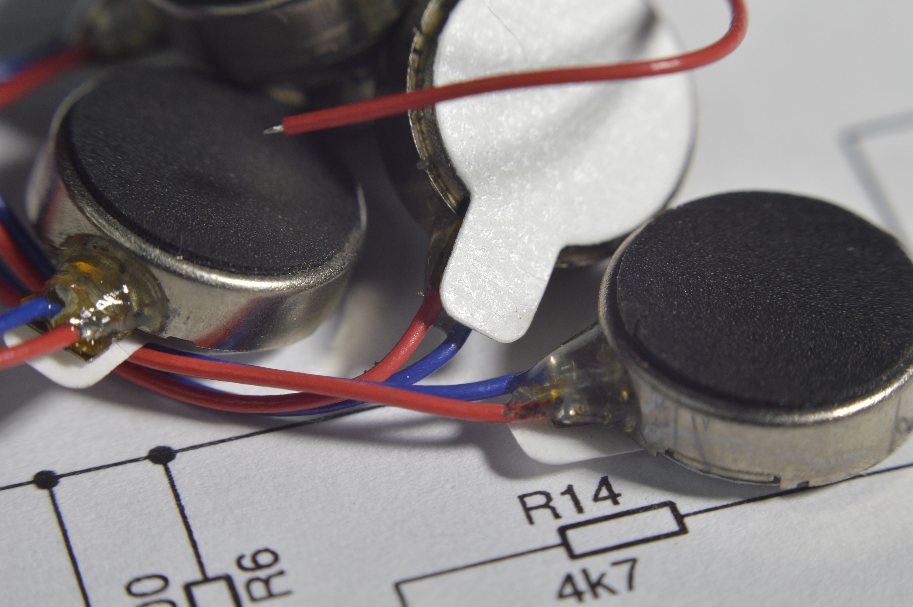
    A bunch of vibration motors:

    A sixth sense without battery?

    The sewn anklet with an extra pocket for the PCB:It's easy to put the sixth sense on:

    It's not so easy to do a three point blind walk :)


  • Add sleep mode

    Sebastian Foerster09/06/2015 at 21:13 0 comments

    woohhhooo... My project made it into the Top 100 chosen semifinalists. How great is that?

    A big thanks to all supporters and especially a big big thanks to Reiner for his video support (coming soon) and Reinhard for his English lessons and video support :)

    I have recently added a new software feature: a sleep mode when the battery gets low. This is important to improve the overall battery lifetime. Of course, a good battery like the one I use has a deep discharge protection. Unfortunately the protection trigger is a bit late ( ~ 3 V). It's always a good idea not to discharge a Lithium-Ion battery below 3,4 V.

    For TheSixthSense PCB it's of major importance to use a LDO with a very low Input Quiescent Current. The Microchip MCP1700 is a good and cheap solution. The 2,5 V version has a typical Iq of 1.6 µA and at higher temperature only 4 µA @ Iout = 0 A.

    The next crucial part is a good schematic design. You should design a voltage divider to measure the battery voltage with a "disconnect function". A P-MOS at the positive voltage rail of the resistor divider is used here.

    The main advantage of parts that have good sleep modes is that they don't need to be disconnected from the voltage supply. Like the LSM303D and the ATXMega32E5:

    LSM303D: Current consumption in power-down IddSL = 1 µA typ.

    Atmel ATXMega32E5: from Datasheet Figure 37-17. Power-down Mode Supply Current vs. Temperature -> @ 25 °C, ~2,5 V => 0.15 µA (no Watchdog, no POR, no RTC)

    Okay, there are 0.15 µA + 1.6 µA + 1 µA = 2.75 µA in theory.

    How is it in practice?

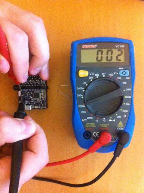
    It’s not so easy to measure those low values, but I measured it with my cheap and out of range multimeter (2000 µA range). The result is a toggling value between 2 and 3 µA ! :)

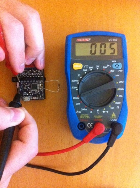
    You can easily verify this reading with 1 Meg Ohm +- 10 % resistor as additional parallel load.

    Toggling 2 to 3 µA reading:

    verify the multimeter reading with an additional 1 Meg Ohm load (2,5 V / 1 Meg Ohm = 2,5 µA additional):

    ~ 2.5 µA current consumtion is almost low enough because a LiPo has a standard self discharge current in this region and higher.

    Check out my new git commit for the software update….

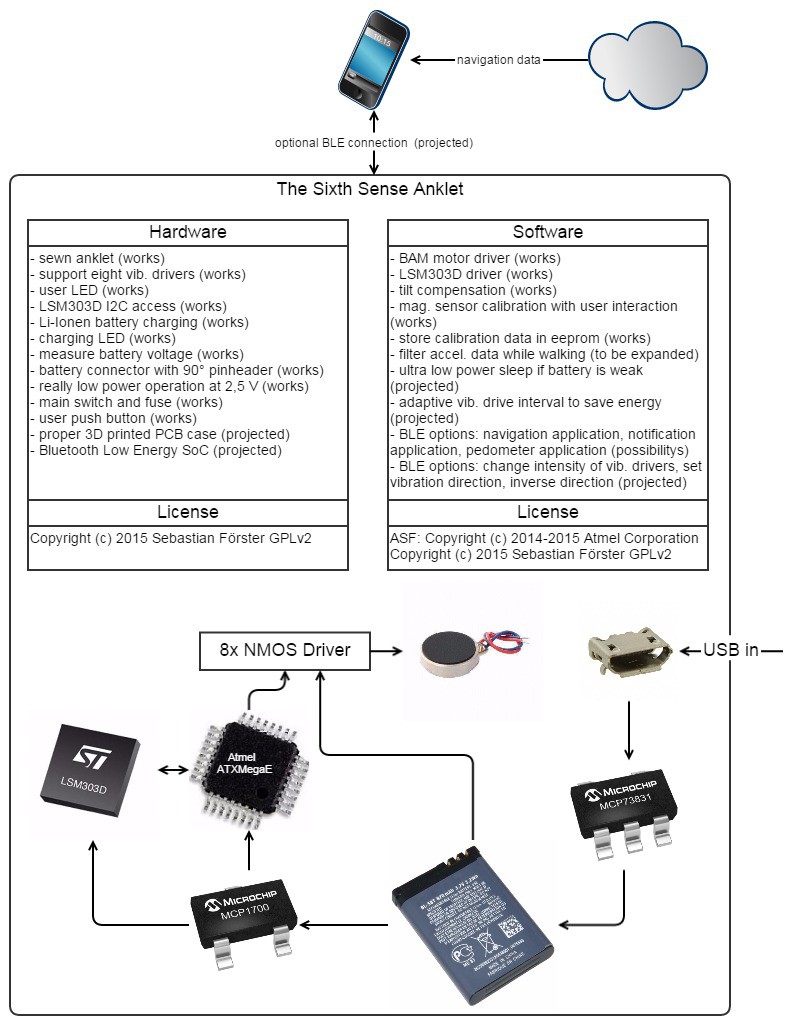
  • System Design

    Sebastian Foerster08/15/2015 at 10:37 0 comments

    In Germany we say: "Die Sprache des Ingenieurs ist die Zeichnung"...

    "the language of the engineer is a drawing"... or so :)


  • v1.3 PCB components list

    Sebastian Foerster08/10/2015 at 18:00 0 comments

    TheSixthSense v1.3 components list; date 10.08.2015


    Quantity Value Mouser Part Number Device Part
    1 10-XX 688-SKSCLAE010 10-XX S3
    2 PINHD-1X1 538-22-28-8020 PINHD-1X1 JP1, JP2
    8 0R 667-ERJ-3GEY0R00V R-EU_R0603 R13, R19, R22, R25, R28, R31, R34, R37
    3 1u 80-C0603C105K8P C-EUC0603 C2, C4, C11
    2 4k7 667-ERJ-3EKF4701V R-EU_R0603 R9, R14
    4 4u7 80-C0603C475K8P C-EUC0603 C3, C8, C9, C12
    23 10k 667-ERJ-3EKF1002V R-EU_R0603 R2, R3, R4, R5, R7, R8, R10, R11, R12, R17, R18, R20, R21, R23, R24, R26, R27, R29, R30, R32, R33, R35, R36
    4 100R 667-ERJ-3EKF1000V R-EU_R0603 R1, R6, R15, R16
    2 100n 80-C0603C104K4R C-EUC0603 C1, C5
    2 220n 80-C0603X224K4R C-EUC0603 C6, C7
    1 10118193-0001LF 649-10118193-0001LF MOLEX-47346-0001 USB1
    1 ALPSSSSS811101 688-SSSS811101 ALPSSSSS811101 S1
    1 ATXMEGA32E5-AU 556-ATXMEGA32E5-AU AVR_XMEGA_E U1
    1 F0603E0R25FSTR 581-F0603E0R25FSTR PMS1812 F1
    1 IRLML 5203 942-IRLML5203TRPBF IRLML5203 Q1
    2 KPGA-1602CGC-KA 859-LTST-S270KGKT APA1606SURCK U6, U7
    1 LSM303D 511-LSM303DTR LSM303D U3
    1 MCP1700T-2502E/TT 579-MCP1700T2502E/TT XC6206P332MR U4
    1 MCP73831 579-MCP73831T-2ATIOT MCP73831 U2
    1 MICROMATCH-16SMD 571-8-2178711-6 MICROMATCH-16SMD X1
    1 PDTC114YT 771-PDTC114YTT/R BC848ALT1SMD Q2
    8 PMEG4010ETR 771-PMEG4010ETR115 MBR0520LT D1, D2, D3, D4, D5, D6, D7, D8
    8 Si2302CDS 781-SI2302CDS-E3 BSS123 Q3, Q4, Q5, Q6, Q7, Q8, Q9, Q10
    1 MICROMATCH-16SMD-Plug 571-8-215083-6

    See also "COMPONENTS"-Section at this project page to don't miss a part.

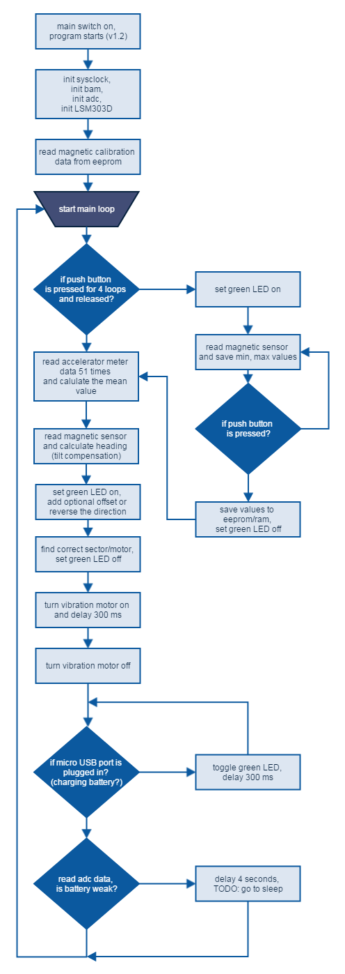
  • Video and program flowchart

    Sebastian Foerster08/09/2015 at 11:28 0 comments

    Hey... my quarterfinals video is done.

    Here it is:

    I made also a nicely looking gliffy flowchart for the ATXMega32E5 microcontroller program.

    I will also add a part list for all components of TheSixthSense PCB v1.3 this week.

    I think that's all for the quarterfinals entry!?

    All licence are documented at github. -> It's for the µC program the Atmel ASF licenes plus my GPLv2 on top and the PCB is a open hardware GPLv2 too.

  • PCB version 1.3

    Sebastian Foerster08/03/2015 at 16:37 0 comments

    I am afraid I am running a bit out of time for the quarter finals. :-/

    I have received the PCB version 1.3 from OSH Park and cut down my old stencil in two parts to solder the most parts (especially the LGA-16 package) in my reflow oven. It looks complicated but it was working like a charm! The hinted pasting process:

    My mouser order was arriving right in time and I added the new push button, main power switch, fuse and micro-match connector.

    I spend half an hour to try to fiddle the micro-match connectors together until I was realizing that I have ordered a micro-match ribbon connector for direct soldering. Unfortunate, but then again it was my first project with micro-match parts.

    Obviously wrong for TheSixthSense project:


    Correct (but must be a 16 pin type):


    I was also adding two cutted 90° pin-headers for the battery connection. The battery fits well but must be hold with a zipties in place since I haven’t designed a well fitting case. The new colorful ribbon cable with the vibration motors looks a bit like art.

    I hope I will receive my new mouser order tomorrow and can start with the 2 minutes video for the contest and more importantly, I could test the new software functions, like starting the calibration process with the new push button interaction.

  • adding more features

    Sebastian Foerster06/21/2015 at 08:42 0 comments

    Before I switch over to a Bluetooth Low Energy solution I was ordering a new PCB (v1.3 see on github) with some added features:

    • main power switch to fully disconnect the battery
    • 250 mA fuse to make sure the anklet can’t be aflame
    • a small push button to start calibration process and future use
    • new “battery connector”/pin headers in position with Nokia 2600 battery terminals
    • micro match connector to disconnect the motors if needed

    I hope I will get the order from oshpark.com in three weeks (shipping time to europe). I will use my old stencil to get only the LSM303D on the board the other components could be easily added by soldering iron.

    It’s interesting if the battery directly under the magnetometer IC is a problem. It should depend on the potential reservoir of ferromagnetic materials in the lithium battery.

    Has anybody experience with that?

  • add eight motor support

    Sebastian Foerster06/16/2015 at 06:08 0 comments

    Through ebay I was able to purchase 30 additional motors from China. Before that point, I used to order the vibration motors from the following link: http://www.seeedstudio.com/depot/Mini-vibration-motor-20mm-p-2300.html. The seeedstudio order is more reliable but a lot more expensive. By chance, the ebay motors seem to be from the same kind. There are some small differences with the DC resistance between each motor and also the resistance is changing after rotation. Maybe it's an indication for decreased commutator quality?!

    Changing Hard- and Software at github

    I have tagged the four motor version in source code and in design at github. If anyone has already started to build the old version, you could still use the correct (older) versions:

    TheSixthSense_XMega is tagged with V1.0

    TheSixthSense-PCB is tagged with V1.1

    I would prefer to use the newest version with eight motor support.

    Whats new

    There aren't so many (eight / 16 bit) PWM Pins on a XMegaE, because I2C data- and clock line is blocking two PWM pins. Thats no problem cause the pwm resolution doesn’t need to be very high. Its enough to have 32 steps to adjust the vibration force to your needs.

    I changed the hardware PWM to a software BAM (http://www.batsocks.co.uk/readme/art_bcm_3.htm)

    Here is my implementation to init a timer with 4 compare interrupts an overflow interrupt using the Atmel Software Framework:

    #define TIMER_RESOLUTION 500 // 250 HZ at 2 MHz and div = 8
    //init BAM with one timer to supply 8 motors with 250 Hz
    void init_bam(void)
    {
    
    /* Unmask clock for ... */
    tc45_enable(&TCC4);
    
    /* Configure TC in normal mode */
    tc45_set_wgm(&TCC4, TC45_WG_NORMAL);
    
    /* Configure period equal to resolution to obtain 250Hz */
    tc45_write_period(&TCC4, TIMER_RESOLUTION);
    
    //no cc outputs
    TCC4.CTRLE = 0;
    
    //bam timing -> 5 Bit possible with ovf vector
    tc45_write_cc_buffer(&TCC4, TC45_CCA, TIMER_RESOLUTION >> 4);
    tc45_write_cc_buffer(&TCC4, TC45_CCB, TIMER_RESOLUTION >> 3);
    tc45_write_cc_buffer(&TCC4, TC45_CCC, TIMER_RESOLUTION >> 2);
    tc45_write_cc_buffer(&TCC4, TC45_CCD, TIMER_RESOLUTION >> 1);
    tc45_set_overflow_interrupt_callback(&TCC4, ovf_interrupt_callback);
    
    tc45_set_cca_interrupt_callback(&TCC4, cca_interrupt_callback);
    tc45_set_ccb_interrupt_callback(&TCC4, ccb_interrupt_callback);
    tc45_set_ccc_interrupt_callback(&TCC4, ccc_interrupt_callback);
    tc45_set_ccd_interrupt_callback(&TCC4, ccd_interrupt_callback);
    
    /*
    * Enable TC interrupts
    */
    
    tc45_set_overflow_interrupt_level(&TCC4, TC45_INT_LVL_LO);
    tc45_set_cca_interrupt_level(&TCC4, TC45_INT_LVL_LO);
    tc45_set_ccb_interrupt_level(&TCC4, TC45_INT_LVL_LO);
    tc45_set_ccc_interrupt_level(&TCC4, TC45_INT_LVL_LO);
    tc45_set_ccd_interrupt_level(&TCC4, TC45_INT_LVL_LO);
    /*
    * Run
    */
    tc45_write_clock_source(&TCC4, TC45_CLKSEL_DIV8_gc);
    
    }

    As you can see it’s rather easy to setup the timer with ASF support.

    Before you could call this function you should define the callback functions for the interrupts. The source code for every interrupt callback is mostly the same. You have just to define which bit should be modulated:

    static void ovf_interrupt_callback(void)
    {
    soft_bam_process(0x01);
    tc45_clear_overflow(&TCC4);
    }
    
    static void cca_interrupt_callback(void)
    {
    soft_bam_process(0x02);
    tc45_clear_cc_interrupt(&TCC4, TC45_CCA);
    }

    ...and so one.

    The function soft_bam_process turns on and off all the motors you could add and you could add so mutch motors you have free digital pins.

    Lets take a look in this function:

    void soft_bam_process(uint8_t bitmask)
    {
    //error if adding motors without changing source
    #if(MOTOR_NUM != 8)
    #error (add more motors here)
    #endif
    
    if(motor_soft_bam[0] & bitmask) {
    gpio_set_pin_high(M1_O);
    } else {
    gpio_set_pin_low(M1_O);
    }
    
    if(motor_soft_bam[1] & bitmask) {
    gpio_set_pin_high(M2_O);
    } else {
    gpio_set_pin_low(M2_O);
    }

    Its good to have some precompiler errors if you try to add more motors and forgot to map this motors to there gpios. The motor_soft_bam array is the new compare register array you could change from the main loop....

    Read more »

View all 9 project logs

  • 1
    Step 1

    Here is my explanation to stitch the anklet.

    First, you should measure the circumference above your ankle. The length dimension (330 mm) in the instruction is perfect for a circumference for about 230 mm.

    A well fitting end product should have the option to switch between three different sizes (S,M,L).

    To keep the spirit of the hackaday prize 2015, please use an old or worn out piece of clothing out of your wardrobe. I think everybody will find one. Perfect would be 100 % cotton, because of the breathable characteristics.

    You will need:

    • sewing needle
    • scissors
    • twine
    • velcro fastener (both sides)
    • measuring tape
    • cloth
    • one and a half hour of your time

    Here is a (hopefully) easy to understand how-to guide:

View all instructions

Enjoy this project?

Share

Discussions

Masoud Gheysari wrote 08/14/2015 at 14:53 point

Use ULN2003 instead of those transistors. Each ULN2003 contains 7 Darlington pairs plus the required resistor and protection diode. It's a cheap, easier, and small replacement for transistors and to drive those vibration motors. You can find it for 10cents per IC and omit the complicated driving circuit you designed. I bet it's a nightmare to solder them clean, but one IC is much much smaller and easier.

  Are you sure? yes | no

Sebastian Foerster wrote 08/15/2015 at 08:31 point

I know the ULN2003 and I could use the ULN2003A part (2,5 V input). But it scares me that I have only seven outputs and must fall back for one motor to a discrete solution.

I didn't hand solder, but you are right with the BOM costs... 

IMO best solution a powerful current source LED driver with I2C or SPI with a additional diodes array. Like here: https://hackaday.io/project/1962-3d-haptic-vest-for-visually-impaired-and-gamers

  Are you sure? yes | no

Masoud Gheysari wrote 08/15/2015 at 12:19 point

So use ULN2803! It's exactly the same as 2003, but with 8 pairs instead of 7.

  Are you sure? yes | no

Sebastian Foerster wrote 08/16/2015 at 11:30 point

But there is another drawback:

Typical Vcesat ~ 0.9 V @ 100 mA is more then 1/4 power loss -> up to 10 hours lesser operation time...

Okay, this linear estimation is only valid if  vibration force and supply voltage will also be linear, but it isn't so.

  Are you sure? yes | no

Masoud Gheysari wrote 08/16/2015 at 11:54 point

Am I missing something? Because I don't understand the difference in power loss between your configuration (discrete transistors with their needed circuits and components) and that exact same configuration on an integrated circuit (ULN2803). Your  have Vce(sat) too, you know!

  Are you sure? yes | no

Sebastian Foerster wrote 08/16/2015 at 16:41 point

MOSFETs have no Vce(sat), they have a Rds(on). In my case (SI2302CDS) Vgs = 2.5 V it is 0.075 Ohm. It's just a drop of 7.5 mV @ 100 mA !

Also there are better bipolars (NPNs) available:  Like the one I used for the battery voltage measurement  (PDTC114Y) -> @ 100 mA max Vce(sat) ~ 100 mV

best regards 

basti

  Are you sure? yes | no

sjbolton wrote 06/19/2015 at 02:12 point

With a small electrical shock this could help with stroke recovery. A stroke left me paralysed down the left side of my body. I've had to fight through paralysis and relearn how to walk and after a year my arm is still unusable. While I have trained my brain to do the large muscle movement needed to stand and walk with a stick its the smaller weaker muscle movement we are never aware of until they are gone that are difficult. Eg one on each foot keeping motion parallel to each other.

So for example when walking i can be distracted by another pedestrian when i need to focus fully on controlling the leg. Instead of stepping forward my leg might instead swing outwards throwing me off balance. Something like this could be helpful in keeping the brain focused on keeping the leg/foot pointed in the right direction (relative to the body). Similarly my arm holds itself across my body as if its in a sling (which it was for months), its difficult to force it to hang by my side on its own, as again something like this that can help the brain relearn to relax the arm to the side.

BTW, there are literally thousands of similar "advances" claiming to help patients in some way, not a single one is available to anyone who really needs it. And it doesn't take much to leave your life in shatters, some things the body can not possibly heal itself from

  Are you sure? yes | no

hex4def6 wrote 06/17/2015 at 16:16 point

Take a look at http://sensebridge.net/projects/northpaw/northpaw-downloads/

Friend of mine made a similar project back in 2010-ish. Looks like he still sells it. Anyway. there's code + schematics there.

  Are you sure? yes | no

Sebastian Foerster wrote 06/17/2015 at 17:49 point

Looks really similar to mine project. =)

The arduino compatibility with sensebridge (northpaw) is for many hackers a huge plus point. But the housing looks a bit strange...

Thx for your tip. I will add the link to my project page.

  Are you sure? yes | no

Rob Parzek wrote 06/03/2015 at 22:30 point

This is fascinating. Would you consider a pair, Left and Right for wider effect? Understandably they'd need to be able to detect each other or sync/signal in some way. You'd only need to cover the outside 180 degree arc of each ankle with motors. Still 8, just split into two units. BtLe on the inner ankle sides? Simple orientation sensor to detect if unit is in L or R orientation upon power up. Maybe they sit on a little charging tray with a center pickup stem so you can pick up the array, spin it to calibrate, put them on and off you go.

  Are you sure? yes | no

Sebastian Foerster wrote 06/07/2015 at 13:35 point

Thx for your feedback. I will surly add BLE in the next version to change settings from a mobile phone and maybe for navigation propose.

  Are you sure? yes | no

Andy Woods wrote 06/03/2015 at 19:33 point

great idea! I've been pondering weaving in tactors into my beard / ear piercings that vibrate / glasses that have a vibration attachment, to portray direction info for a good while but never got around to it. Do ping me if you'd be up for some psychological testing of your project (I'm a member of http://www.psy.ox.ac.uk/research/crossmodal-research-laboratory and we love this sort of thing).

  Are you sure? yes | no

Sebastian Foerster wrote 06/07/2015 at 13:10 point

Hi Andy, I appreciate your Feedback very much! And thank you for your kind offer. I consider to ping you as soon my project will have made somewhat more progress.

  Are you sure? yes | no

Similar Projects

Does this project spark your interest?

Become a member to follow this project and never miss any updates