Alex Rich
-
Magnifier, Magnetic Holder, Extended Link
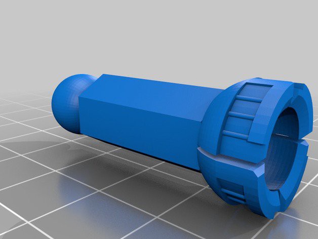
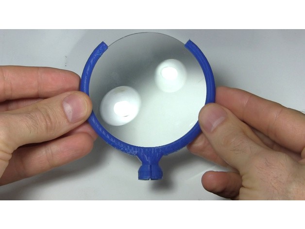
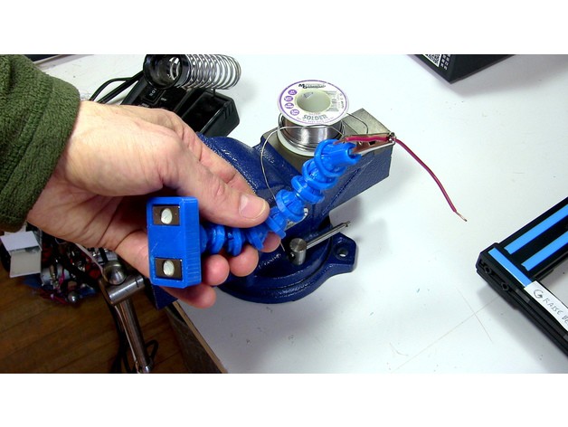
01/26/2018 at 15:50 • 0 commentsSome great accessories developed by stevendpe and posted today on thingiverse:
Magnetic holder: https://www.thingiverse.com/thing:2770722
Magnifying glass holder: https://www.thingiverse.com/thing:2769252
2x Extended Link: https://www.thingiverse.com/thing:2770809
![]()
![]()
![]()
-
Better design for printers without Sol. Support
03/20/2016 at 23:01 • 0 comments -
A make of my thing
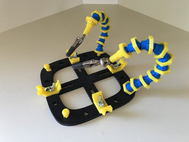
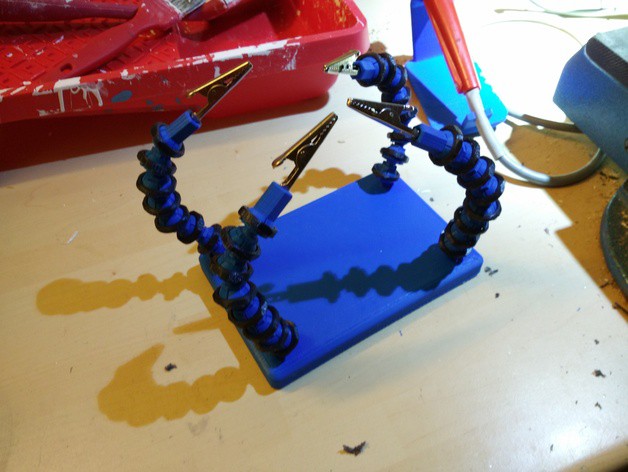
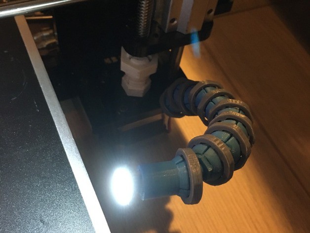
02/25/2016 at 12:48 • 0 commentsA couple people on thingivierse have made arms, thought I would share here. The first is a helping hand workstation with four hands, the second is a gooseneck light for a 3d printer. Cool!
http://www.thingiverse.com/make:198832
![]()
http://www.thingiverse.com/make:193795
![]()
![]()
-
LED Lamp Prototype Pics
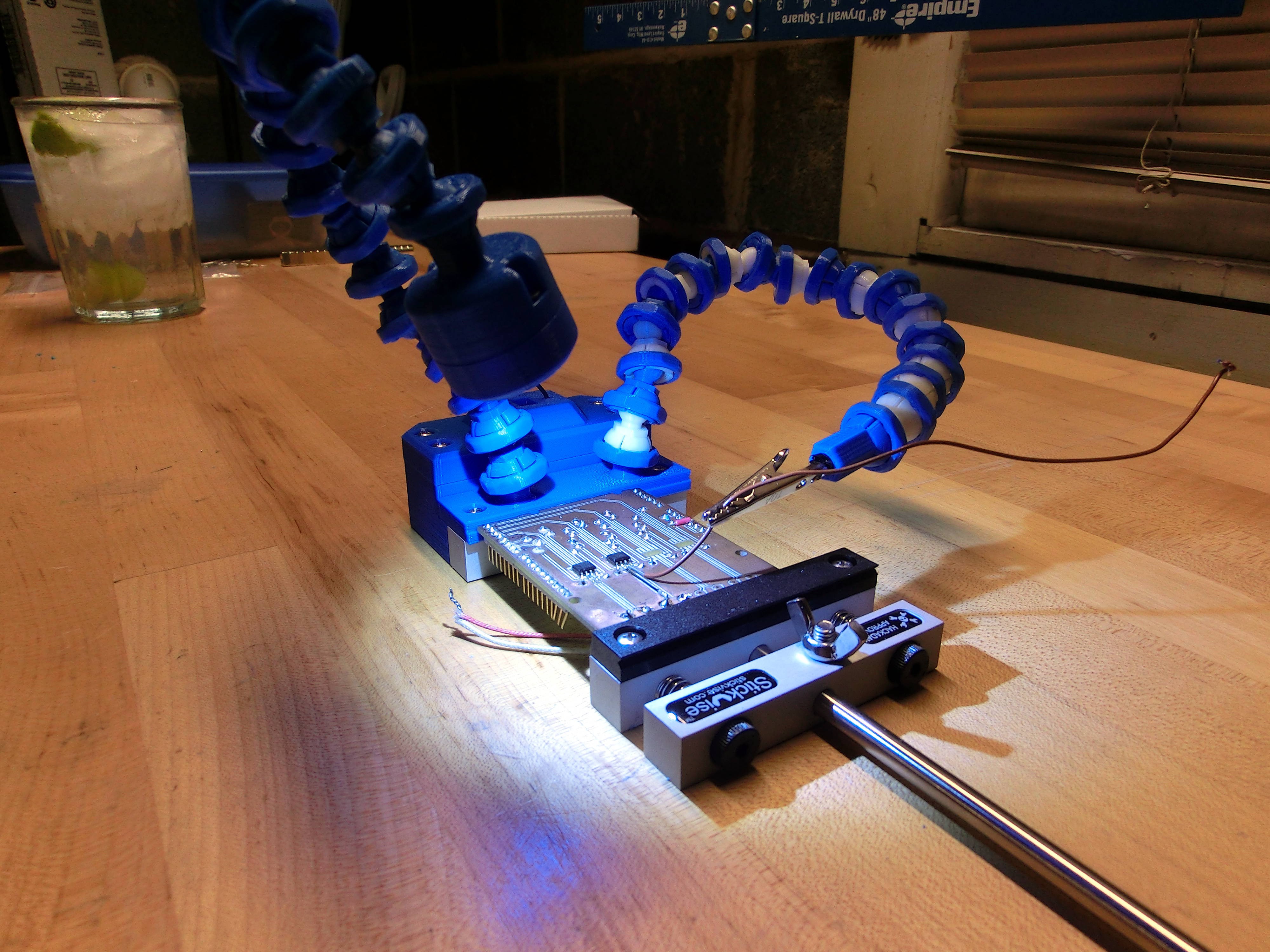
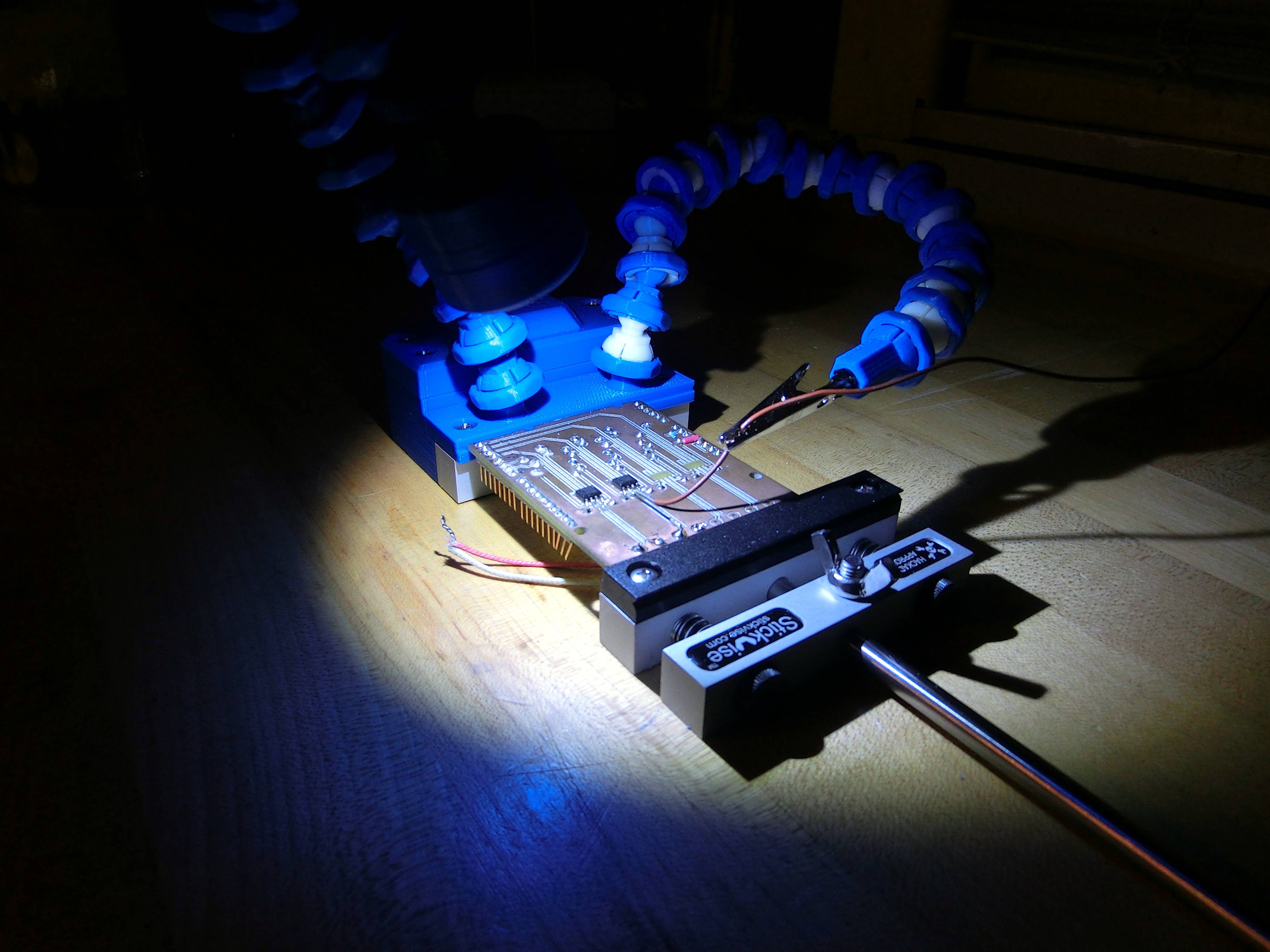
09/11/2015 at 01:18 • 2 commentsOne of the biggest pains in the ass when soldering is not having enough light, it is great to have a nice, bright spot light on your board. This prototype includes an attachment for Stickvise which houses a 9V battery and a simple slide switch to turn the lamp on and off. The LED I used is a really bright module with an aluminum PCB heat sink available on adafruit (http://www.adafruit.com/product/518).
In the pics below the brightness represents ~250 mA being pushed through the LED. I'm happy with the brightness, but at 250 mA a 9V battery has about 300-400 mAh life which means the battery should last about an hour and a half. Not ideal, maybe I will just power this with a USB power supply on my next rev.
![]()
Yes, that's an extra large G&T. It's thirsty Thursday after all, sorry I'm not sorry!
![]()
-
Lamp design finished
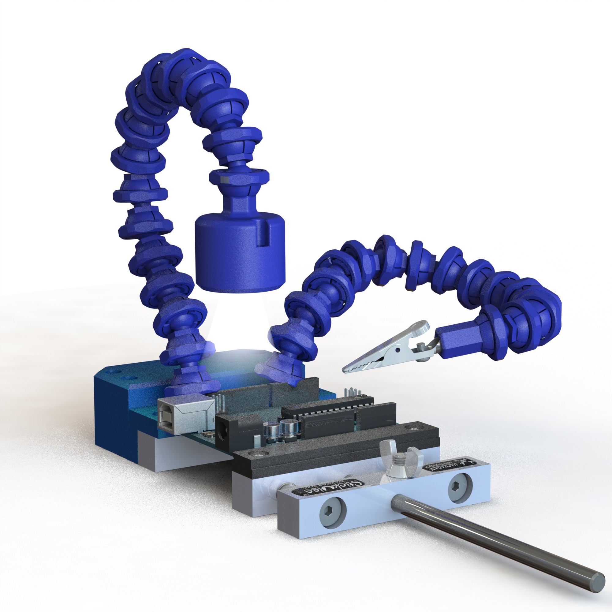
09/03/2015 at 00:33 • 0 commentsCheck out this rendering of my lamp design! The metal materials came out a little bit blue looking but I was tired of tinkering with it. Overall I think it is pretty cool looking.
The lamp uses a 1 W LED from Adafruit, product id 518. The power source is a 9V battery which dovetails into a special jaw plate for Stickvise. More info to come once I get a chance to build everything up and test it, I will release the files once I am happy with it.
A side effect of this experiment is that I realized the ball and socket system works even better with copper wire running through the linkages. It adds a little extra damping/resistance to the bending which gives it a nice feel!
![]()
-
Lamp Design
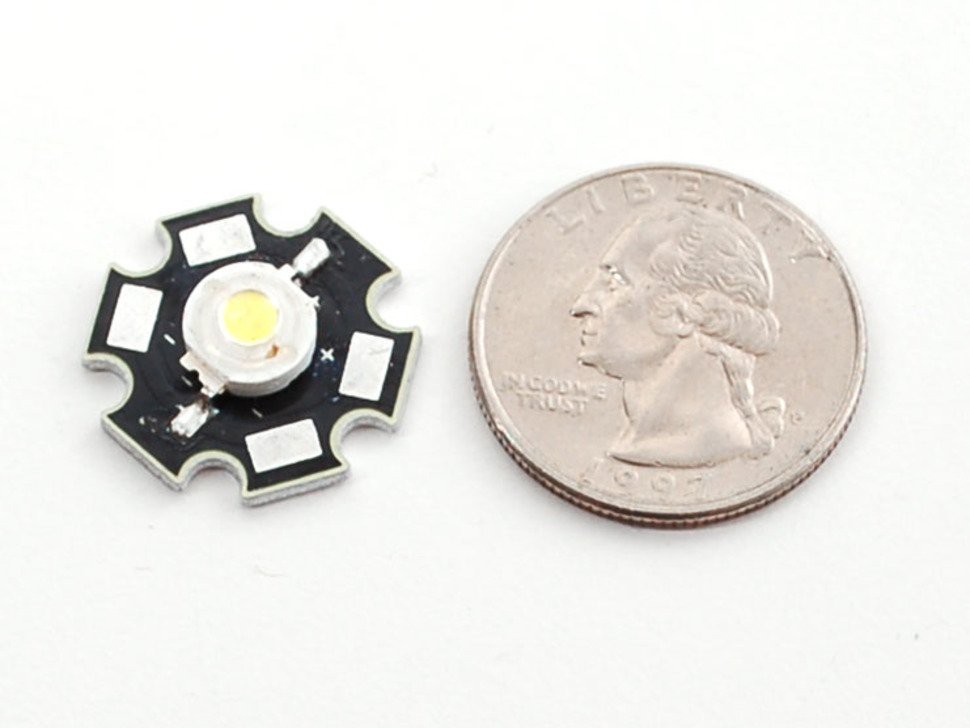
07/15/2015 at 16:13 • 0 commentsOk finally got back around to designing some accessories for this gooseneck system. First I wanted to make a simple lamp, so I decided to order this little LED module from Adafruit, (product ID 518). My plan is to design a 3d printable housing that attaches to my ball and socket arm. I will power it with a cell phone charger. Will update when I have a prototype finished.
![]()
-
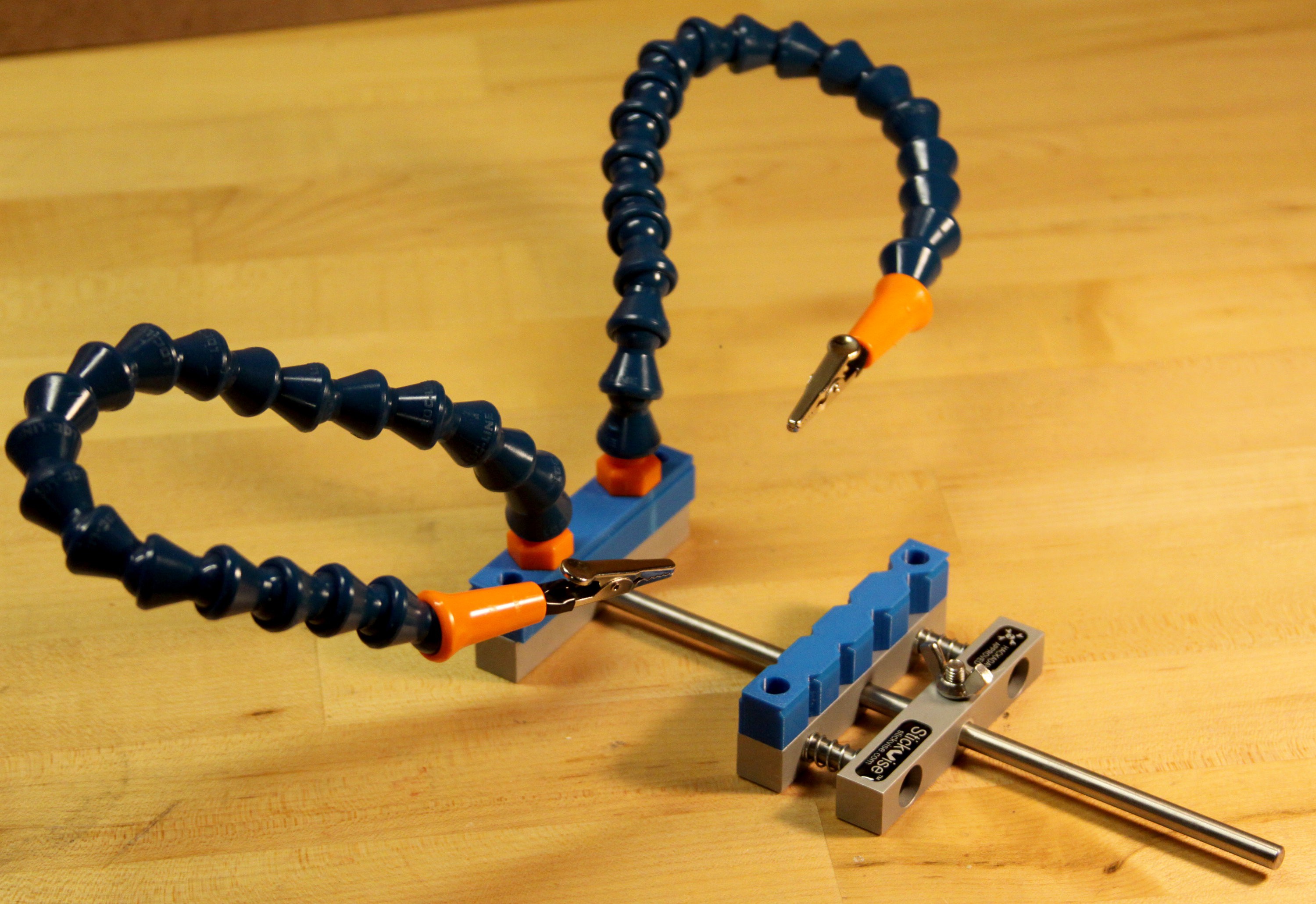
Evaluation of loc-line brand "coolant arms"
05/23/2015 at 02:45 • 0 commentsLoc-line arms:
![]()
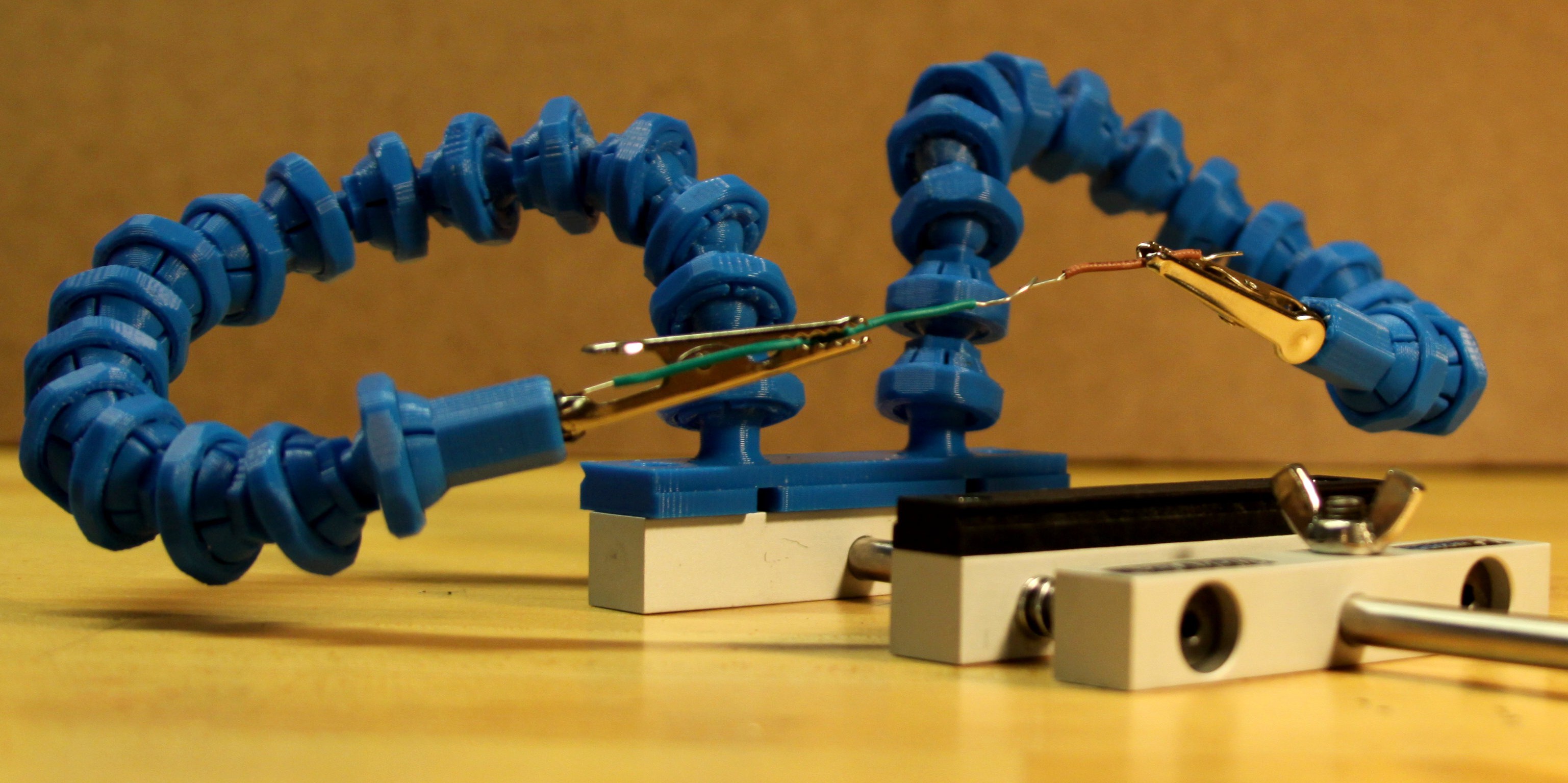
My gooseneck:
I recently purchased a set of loc-line brand coolant arms to evaluate and compare with my 3d printable gooseneck system. If you're not familiar with them, these arms are designed to direct flood coolant towards cutting tools on CNC machining equipment. They are extremely vibration proof and do not spring back at all once you have pointed them in a certain direction. Recently these have become insanely popular to use as helping hands or third hands for soldering. Sparkfun sells them and this instructable has hundreds of thousands of views.![]()
I tested a bit and this is what I found:
Pros:
1. They are cheap, two loc-line arms cost less than $20 with shipping
2. No 3D printer required, only some tools to make a platform to mount the arms on (can be made of metal, wood, plastic, whatever).
3. They hold! Without a doubt, these arms stay exactly where they are aimed until you intentionally move them.
4. No spring back - unlike the metal coil goosenecks, the ball and socket joints have no spring back.
Cons:
1. Loc-line arms are really, really stiff. This is good if you want your arms to stay put no matter what, but it makes fine adjustments difficult because the force required to move the joints causes the entire arm to "jump" from one position to the other.
2. Loc-line arms are hard to take apart and put back together. The joints just aren't designed for frequent disassembly, they are designed to have excellent holding power. Assembly is difficult enough that they actually make a special plier-like hand tool for this purpose.
Comparison to my 3d printed gooseneck:
- My gooseneck is easier assemble / disassemble, at any time you can twist off the lock nut and take it apart to remove or change the tool on the end of the gooseneck.
- Loc-line has a stronger hold, but the hold on my gooseneck isn't bad. For instance both can hold a USB cable in place no problem.
- Loc-line requires some machining skills to mount, a hole must be drilled and an NPT thread needs to be tapped to mount the arms.
Verdict? If you have a 3D printer, try my system before you buy loc-line arms. You might be surprised at how well they work.
*Loc-line coolant arms were purchased at McMaster Carr using part number 10095K11
-
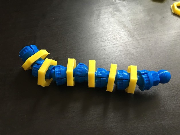
V4 tested and working
05/17/2015 at 19:23 • 0 commentsTested my new spin and think this will work much better. With my printer I am able to turn past first two "locked" positions by hand, the third position I need a wrench to get to. In the third position the ball is very hard to move, I think this position will be useful over time as the ball and socket wear and things get loose, you will be able to tick the tension up a notch to compensate.
More from my version description:
"V4(5/17/15): Redesigned nut so that it fits on the socket regardless of the accuracy and layer height of the printer (within reason). See gif below illustrating the principle. Basically on a more accurate printer the ball will fit better int he socket, not expanding it as much. On less accurate printers the socket expands more. Depending on the expansion, the nut can be tightened to up to three "locked" positions. So you won't have a loose fit on a high accuracy printer but will have no problem getting the nut to turn on a low accuracy printer."
-
Animation
05/16/2015 at 17:01 • 0 commentsI made this animation to show the principle behind my one size fits all lock. My previous design had one locked position which worked on my 3d printer, but many others reported the nut would not turn. To fix this I am working on a design that incorporates several "locked" positions. On a really accurate printer the first position may be too loose, but you can easily tick to the next position until getting a tight fit. On a low accuracy printer I am hoping lock position 1 will be loose enough to allow the nut to turn.
![]()
-
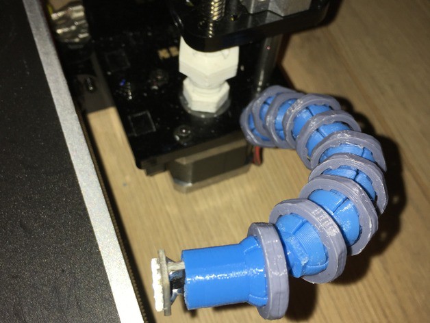
Picture of functional prototype
05/16/2015 at 01:59 • 0 commentsThis thing works great so far, It can turn all the way back on itself with 16 joints, that is what I would recommend printing right now (first test two joints to make sure the fit works on your printer).
![]()
I am working on a new design for the locking nut that will be much more forgiving for different printers from entry level all the way up to a $25k stratasys. Stand by for that, I don't want to release my new design until I have had a chance to fully test it.
Locking ball and socket gooseneck system
3D printed ball and socket joint with a quarter turn twist lock at each joint. Brick shithouse goosenecks!