 Joseph Lavoie
-
1Step 1
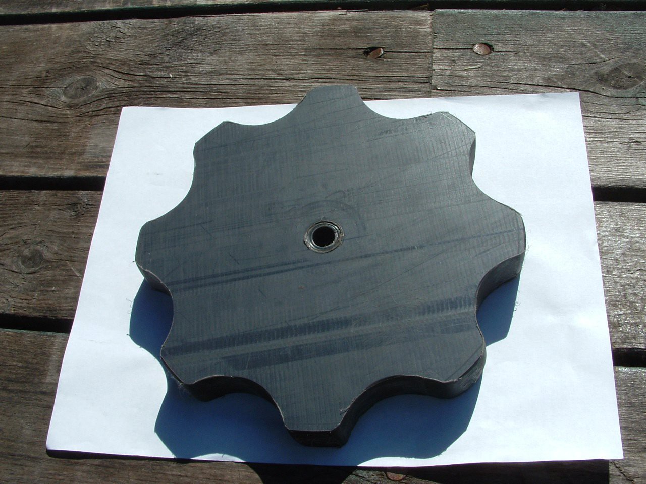
The drive gears are made of 1" nylatron plastic. A very strong material with a lubricant impregnated into it. Here is the blank : 8 inches in diameter.
![]()
-
2Step 2
Using a 1" wood drill bit and hack saw and a belt sander I formed the main drive gear. Several hours of work and viola a gear.
![]()
-
3Step 3
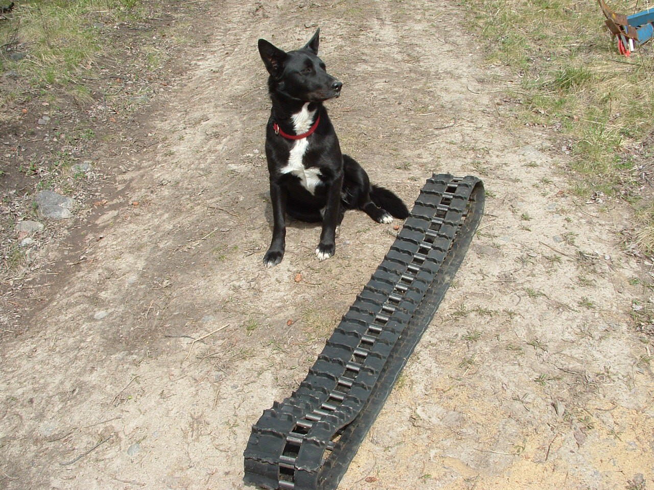
The Track was split down the middle. Using a zip cut disk and lots of time I was able to produce two mirrored tracks.
![]()
-
4Step 4
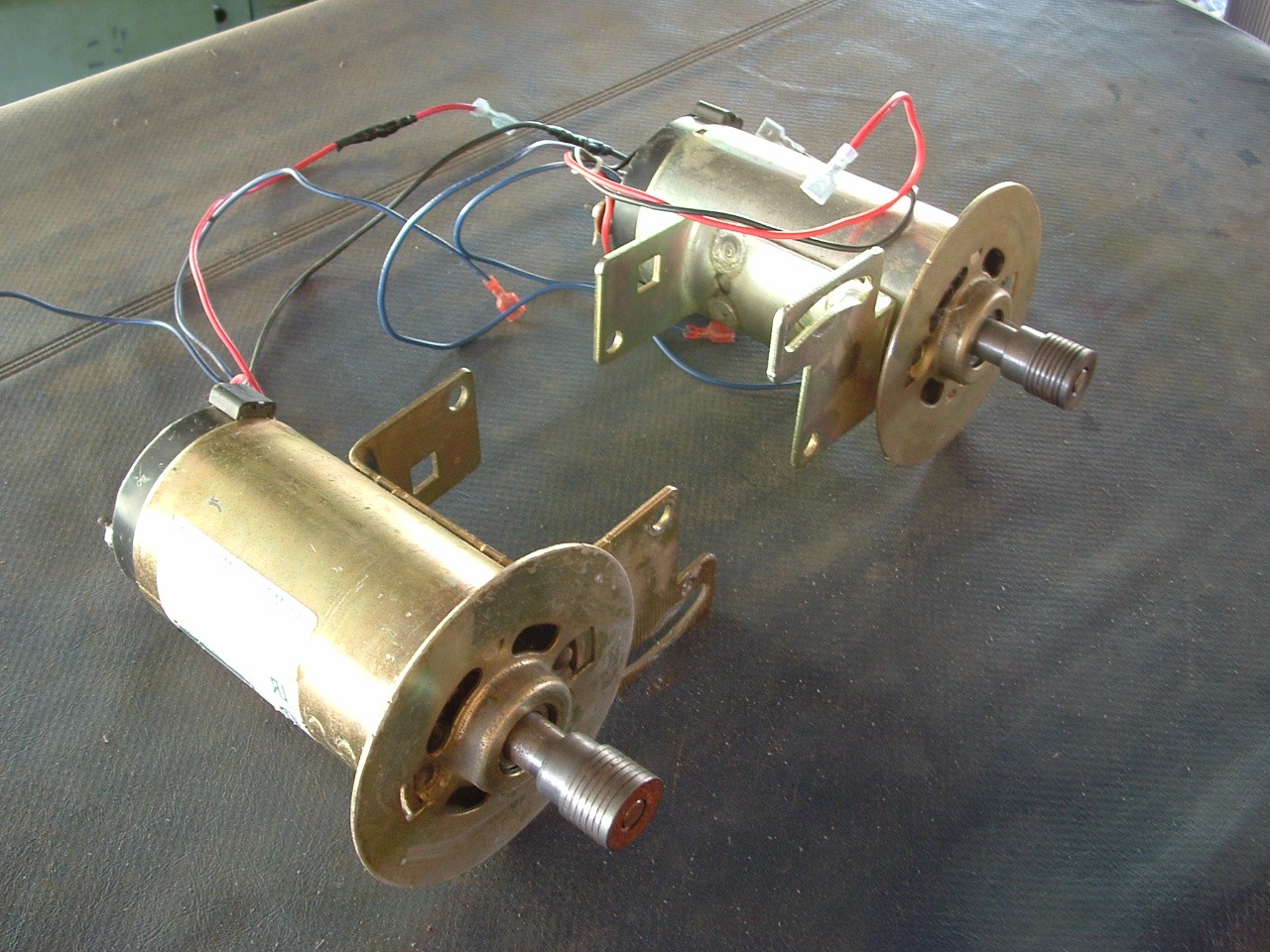
I will start with two modified treadmill motors to power the mover. The cooling of the motors is important and the fans, flywheels will be replaced with a better system.
Here you can see the heavy flywheels have been machined off.
![]()
-
5Step 5
These motors combined will develop 3 hp at 3600 rpm.
-
6Step 6
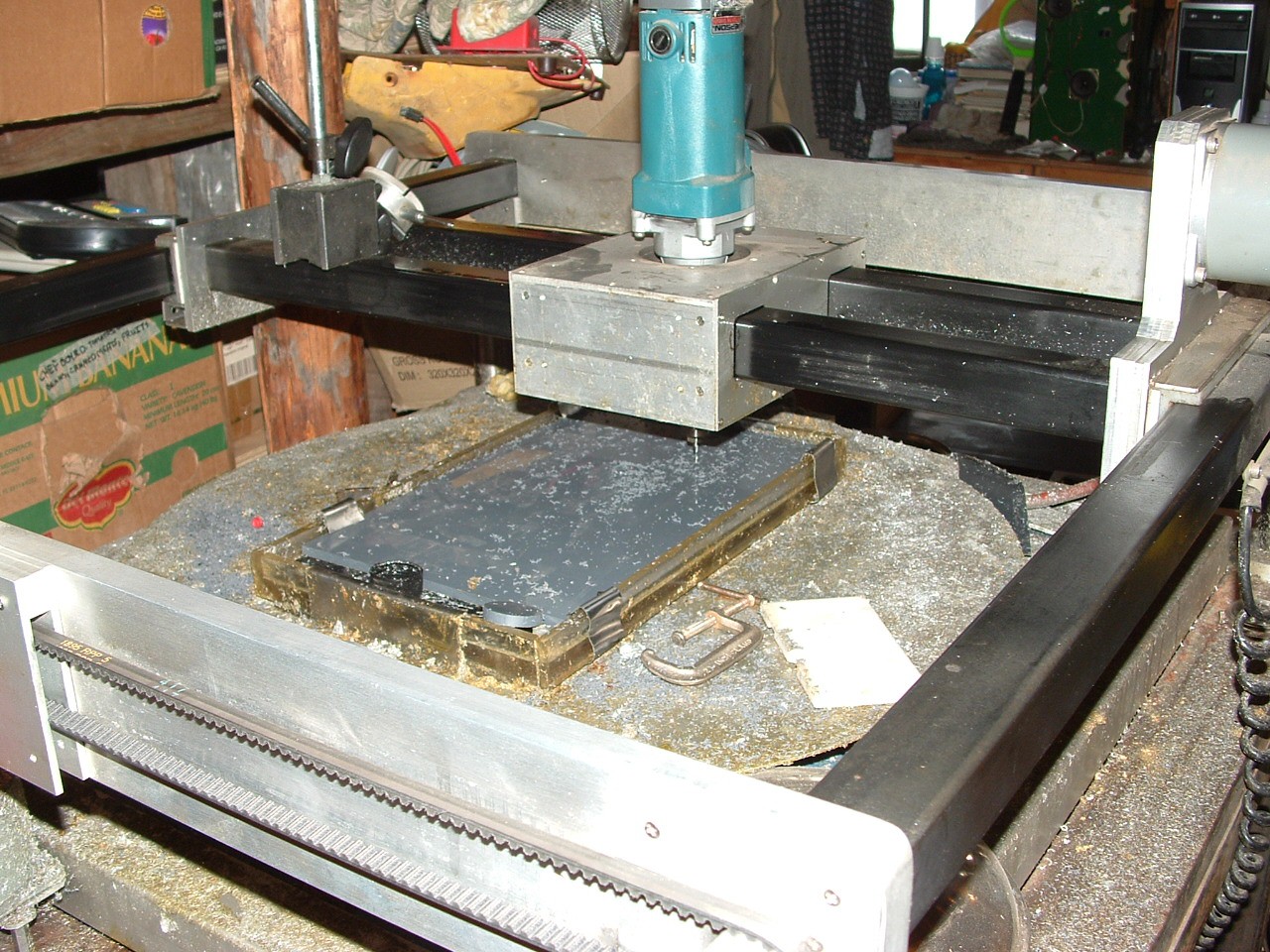
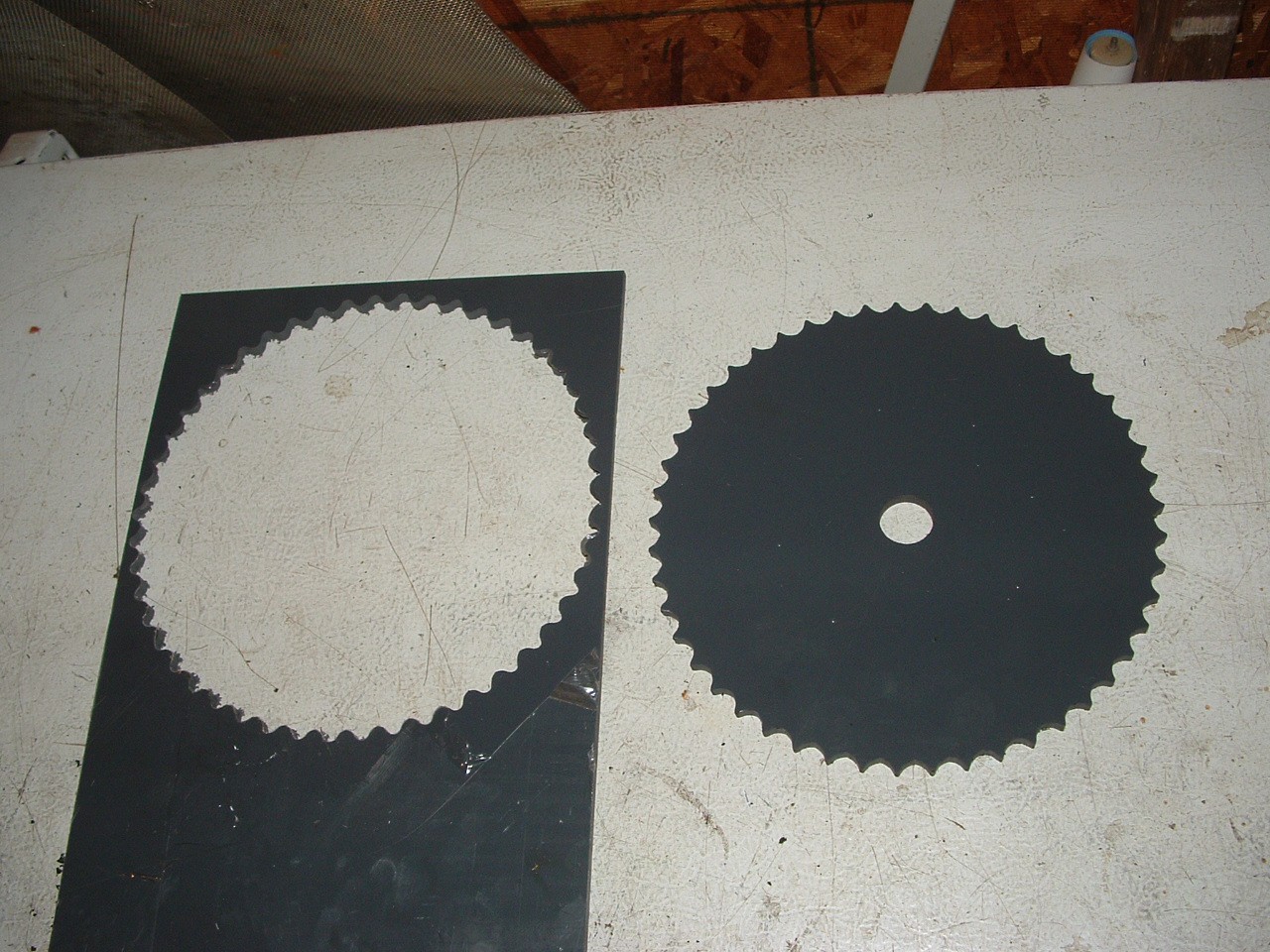
The drive motors will be connected to the main gear by a 15.9 to 1 reduction. Here is the first cut done on my cnc machine.
Here the machine is cutting a 40A49 sprocket from 1/4 " nylatron flat stock. This material is strong and cuts easily at low speed. I am using a 2mil end mill cutter.
![]()
-
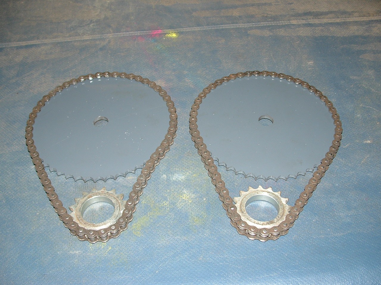
7Step 7
The finished sprocket finished in 23 minutes.
![]()
Two sprockets and I move on.
![]()
-
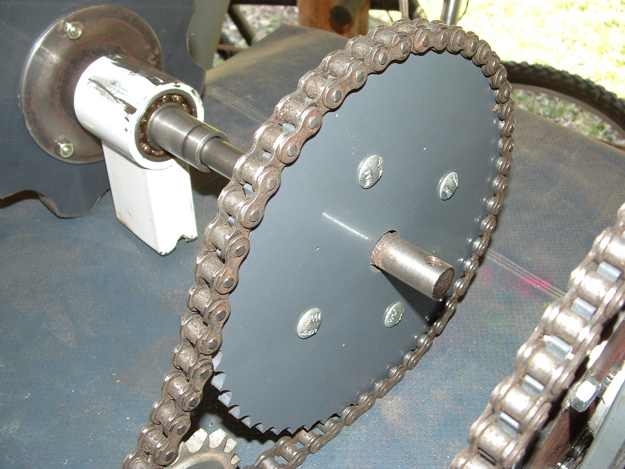
8Step 8
The are the hubs partially assembled.
![]()
-
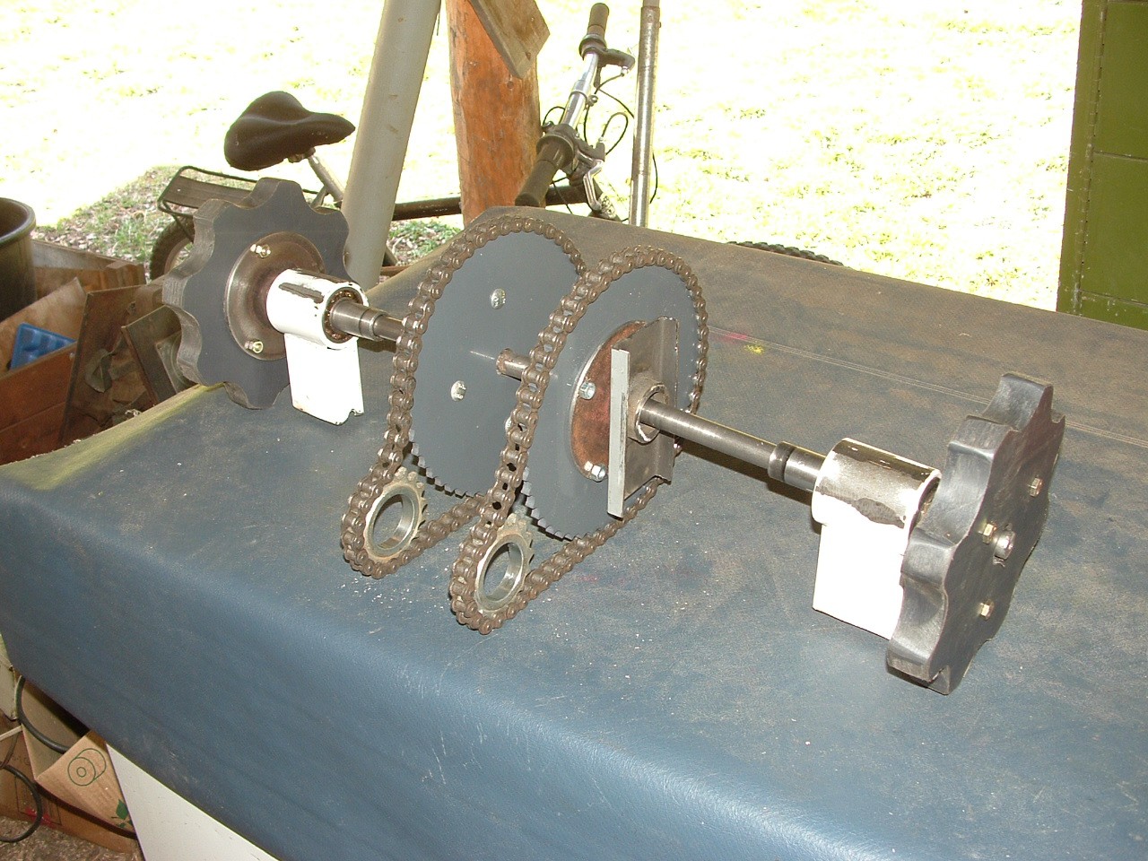
9Step 9
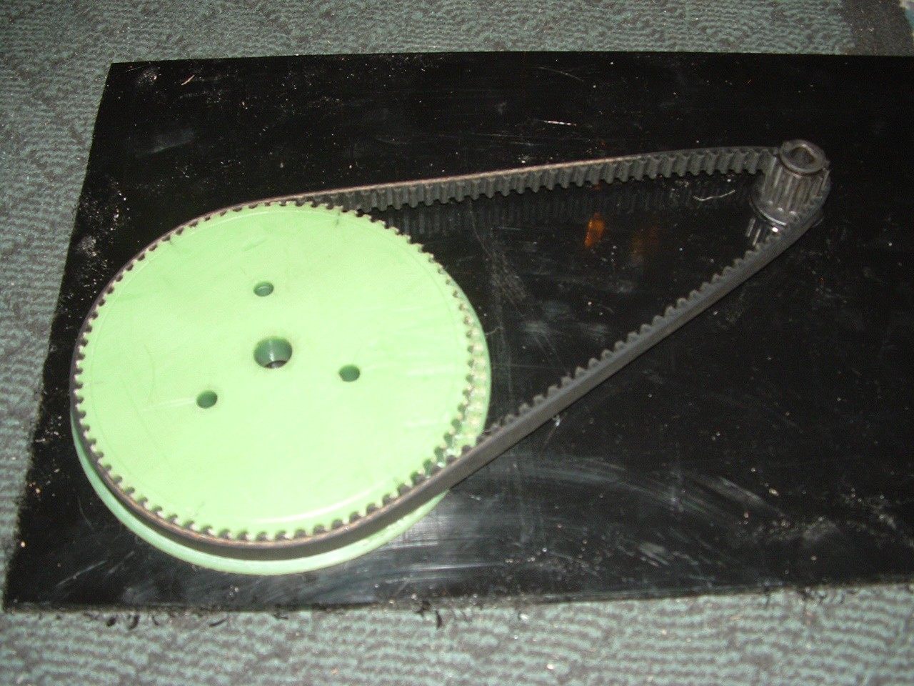
![]()
Here is the second reduction gear assembly. The motor pinion has 13 teeth and the green nylatron has 72 teeth. This reduction is ~ 5.54. Total 5.54 X 2.88 = 15.9 : 1 .
![]()
-
10Step 10
Track Mover Speed Estimated:
0 to 7.386 MPH
6200 Motor RPM / 15.9 gear reduction = 390 RPM Main Drive Cog.
390 RPM / 60 = 6.5 RPS
6.5 RPS X 20 " Cog diameter = 130 Inches per second
130 inches per second of the track = 7.386 MPH
Average walking speed = 3 MPH
Track mover
This project will use old arctic cat parts to evolve into a personal tracked mover..

Discussions
Become a Hackaday.io Member
Create an account to leave a comment. Already have an account? Log In.