Crypto [Neo]
-
29hrs - Complete!
05/17/2015 at 09:12 • 0 comments![]()
So I'm calling this project complete! I've met all my goals, I have all the gerber files and a BOM which I could post online if I wanted. This PIC18F65F94 is really an amazing piece of work, I used the 64-pin variant and I'm glad I chose that one because I ended up using EVERY pin on the thing for this project; and being able to simply map the functions to the requisite pin made setting up everything a breeze! Here's a list of the features:
- PIC18F65F94 @ 48Mhz
- USB Programmable and charged
- PCB mounted breadboard for easy prototyping
- 20 remappable pins for use in your projects!
- 128x16 pixel LCD screen.
- MEMS Speaker and Microphone
- Infrared Proximity and Ambient Light detector
- Infrared Transmitter & Receiver
- 4 Super Bright LEDs and a RGB Led
- 2 Resistive Touch Buttons
- MicroSD Card Slot
I think I remembered everything there :)
I had just enough pins to add 4 LEDS and 2 Resistive Touch buttons at the very end. I'm going to add a header to access the main I2C and SPI buses, that's the only immediate improvement for Erzielboard that I can think of.
If you like Erzielboard let me know! Leave a comment and let us know what you think!
-
25hrs - PCB Finalization
05/17/2015 at 05:47 • 0 comments![]()
First, do you have a feature you'd like to see on Erzielboard that would make it PERFECT for you? Leave a comment and let us know! Alright, now that I've said that...
the PCB is done! I'm verifying everything right now to be sure it'll be functional, I've made extensive use of Microchips remappable peripherals on this device, this allows me to really have the freedom to attach any device nearly anywhere I want! I may start using this device more in the future just for this reason.
I haven't priced the device yet but it shouldn't be too expensive. The most expensive part is the LCD which is $13-15. I doubt it'll cost too much. I'm having to stop myself from adding all sorts of goodies additional like an IMU and Environmental sensor as these should be added yourself by the philosophy of the design. It's supposed to be a protoboard/devkit combination so it shouldn't have tons of stuff.
That being said, I wanted to add some commonly sought after things like a microphone/speaker, MicroSD card reader, and LCD screen because these normally take up quite a bit of protoboard/breadboard space when prototyping.
Basically this dog is done, I actually slacked off a LOT during this one...so until the challenge ends I'm going to be refining the design as much as possible, and possibly adding new things.
-
20hr Update - PCB Routing
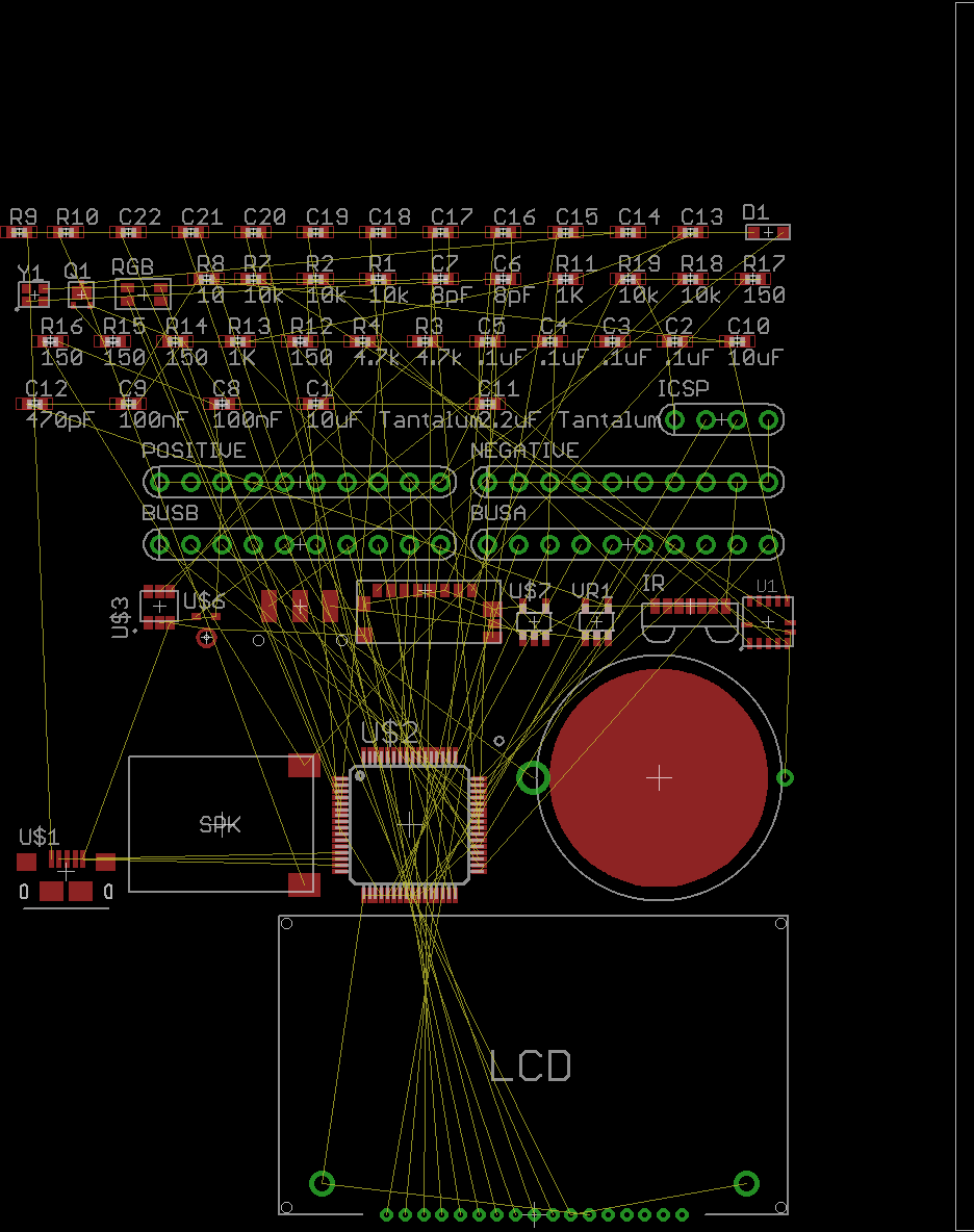
05/16/2015 at 23:54 • 0 commentsSo I'm about 98% done with the PCB routing, I took a lot of time to experiment with different routings for the bus lines to find a design that would allow me the most possible space for the rest of the components. I started with a ratsnest like this
![]()
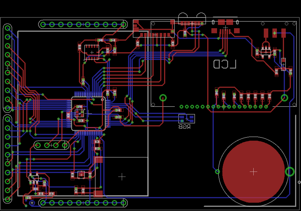
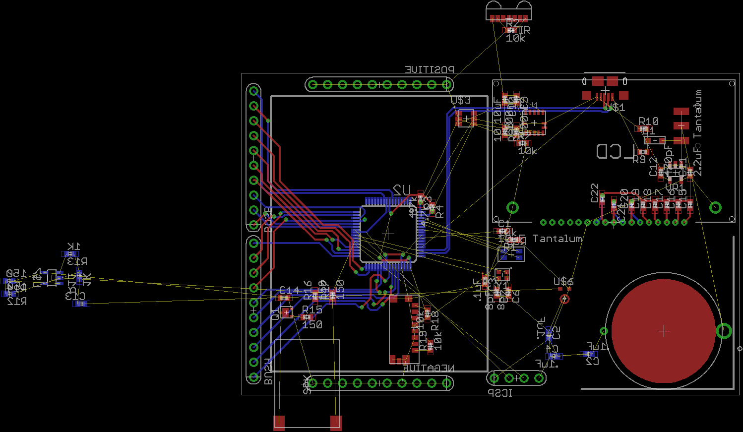
And reorganized components and the bus lines into a nice configuration that groups the ICs with their resistors and capacitors. At this point in the design I'd found the bus line configuration that I was happy with:
![]()
Timestamp: ~`18hrs in
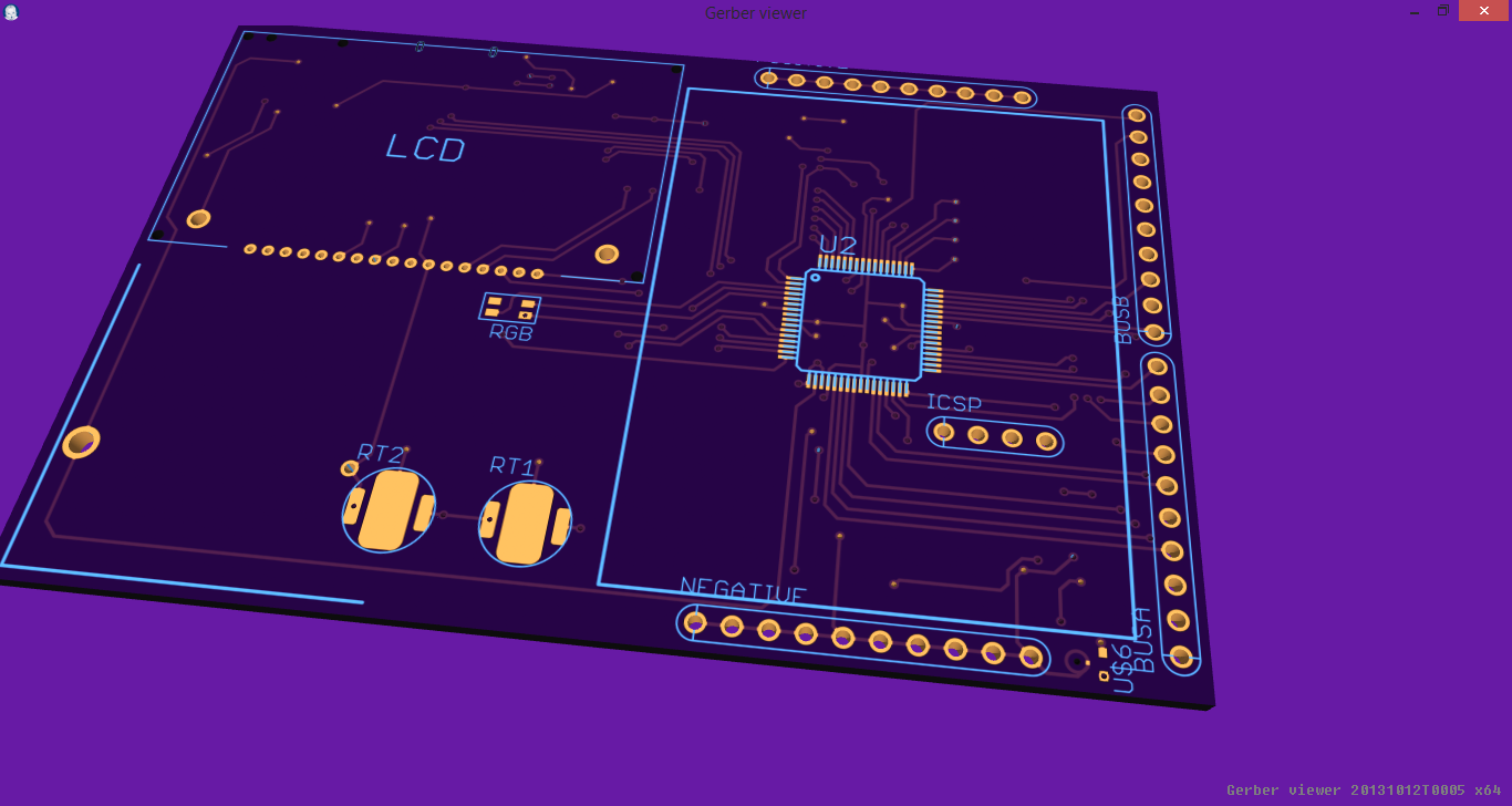
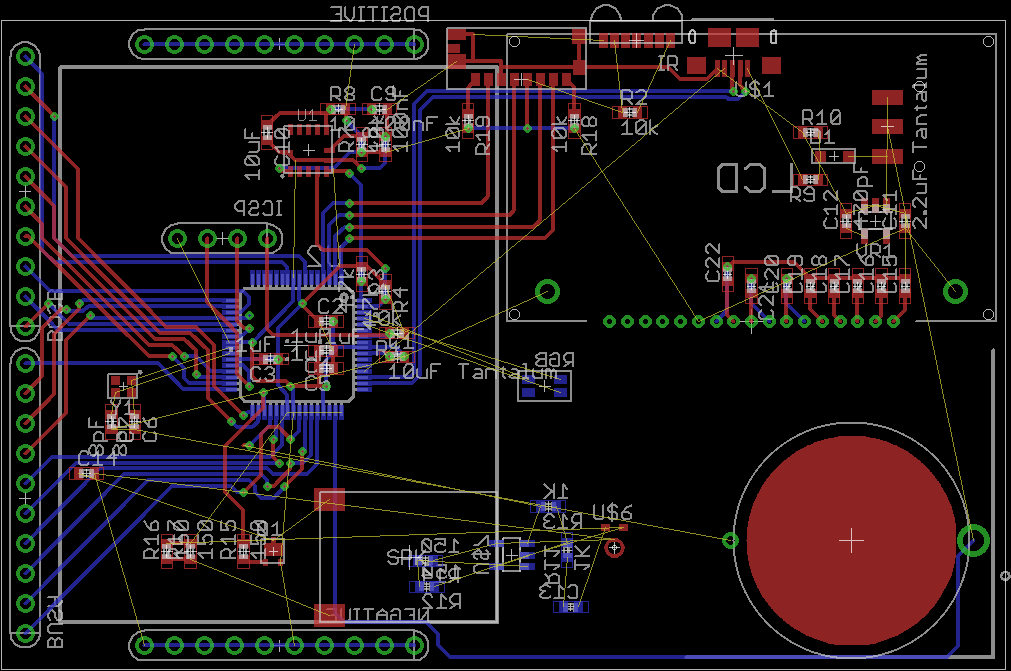
And finally routing everything else into place. The fun thing is that usually during this process stuff gets moved around into even better configurations. Once the initial routing is complete we can go back over it and compact everything a bit.
![]()
TImestamp: ~20hrs in
This was actually a nice challenge to route because I have so much damn space to work with!! I'm so used to be space constrained that actually having so much freedom is actually a hindrance!
Anyways, it's break time for dinner. I haven't be able to really focus on this thing today, which is why the updates have been so sporadic (and why the PCB isn't done yet!) but afterwards I'll be able to actually get some real work done :D I'll be really surprised if the PCB isn't finished by midnight. Then I can focus on adding a few things I'd like to see, and actually keeping tabs on my progress.
-
Peripheral Bus Pinout
05/16/2015 at 16:43 • 0 commentsI think this should be the final pinout for the 20-pin expansion bus on the Erzielboard.
Bus Pin Common Port Remappable Port 1 RA0 RP0 2 RA1 RP1 3 RA2 RP2 4 RA3 RP3 5 RA4 RP4 6 RA5 RP5 7 RB3 RP7 8 RB0 RP8 9 RB1 RP9 10 RC2 RP11 11 RB4 RP12 12 RB5 RP13 13 RB2 RP14 14 RC3 RP15 15 RC5 RP16 16 RC4 RP17 17 RC6 RP18 18 RC7 RP19 19 RD0 RP20 20 RD1 RP21 -
11hr Update
05/16/2015 at 15:15 • 0 commentso we're almost 12 hours into our challenge and I've been slacking on the updates, sorry about that! The Schematic is (mostly) complete, I made extensive use of eagleCADs features to make this quick and painless. It's still a mess, so I'm going to refrain from posting any pictures of the schematic currently.
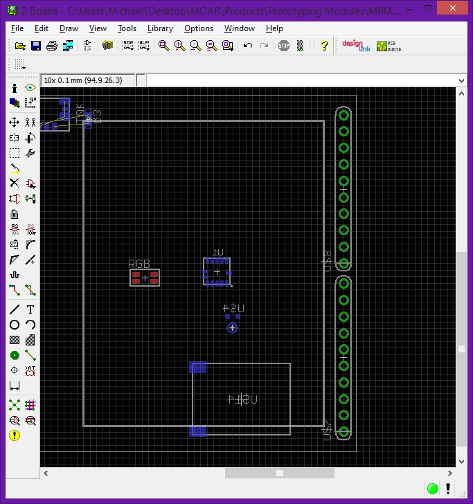
Routing on the PCB side is going smoothly as well, it's quite a difference to work with such a large space compared to PICxie from last weekend. I'm having a lot of fun with it. For this project we decided to use the PIC18F65J94 which is AWESOME! It has a lot of remappable pins, which I'm making full use off by expanding them out into some headers placed near the breadboard.
![]()
These are all going to be routed to remappable pins so it'll be easy to route any of those functions to the breadboard without having to use DIP switches are jumpers!
-
4th hour Progress
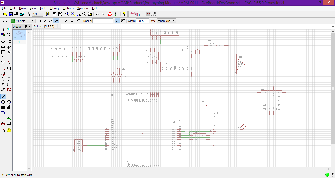
05/16/2015 at 07:47 • 0 commentsSo we've finished selecting the parts mostly, we shouldn't have any problems adding a few here and there. The library has been updated with the new parts. I really need to get one of the guys to go in there and clean it up though. Then we can merge it back into our main branch for our eagleCAD libraries.
![]()
The schematic is coming along. I'm about at the same point I was at last weekend in terms of that. Although this weekend I'm adding less parts onto a larger space so it will be a lot easier to route it I think.
Now time for a nap, and tomorrow I'll finish up the schematic and hopefully the PCB.
-
48hrs and counting!
05/16/2015 at 04:01 • 0 commentsErzielboard is officially go! This isn't much of an update, but now the work can actually begin! See you in a few!
-
T-Minus: 00:30:00
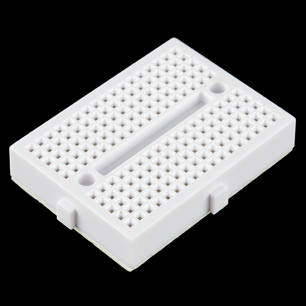
05/16/2015 at 03:39 • 0 commentsOnly about 30 minutes until the start of this weekends challenge. Like I said I've been doing research and I stumbled across a this little guy.
![]()
I was planning on just making up a breadboard area using some headers and the PCB itself. But this tiny breadboard is the perfect size as well as allowing us full use of the space beneath it save the mounting holes
Erzielboard
Erzielboard is a business card sized breadboard/development kit combination that's perfect for your next project!