 C. Prichard
Living Off-Grid in Wales UK - (inverter overloading confirmed)
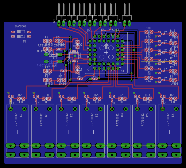
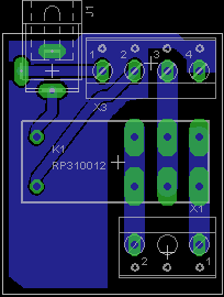
LAST UPDATE: 3-21-16 ATF1500A logic infusion. Resistor arrays? Open area is for DC supply components. Compare to the picture at the bottom.
Achieved WINCUPL compilations of three PAL devices. ATF1500T allows consolidation desired for concise design, reprogrammable, configurable, easily manufactured. Am now working to consolidate this effort to include the WINCUPL output for the ATF1500T, and other components, associated EAGLE components, and LTSpice simulations.
WINCUPL ATF1500T logic (below)
Improved logic integration resulted from attempt to design the board for testing the time base. I realized the logic gates can be added to the programmable logic array device. I need to port this part of the project out, but it makes the build much better for manufacture.
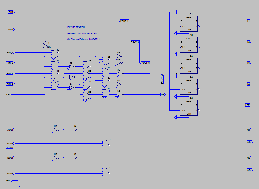
Result is a simpler-looking design. I decided the time base is not easily implemented using OTS parts. When seen this way (below) it looks pretty good.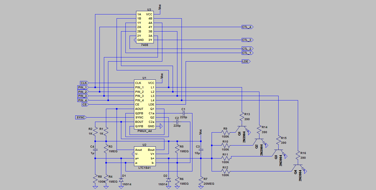 I'm looking for someone to program the logic.
BTW: A nice feature of the Inductive Load Center device is that it becomes practical to then disable the controlled devices, favoring use of power tools without interruption from a pump or other load. Just a flip of a switch can eliminate inconvenience, and resetting the inverter.
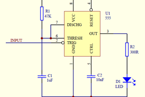
1-22-16 Progress at an implemtation of the retriggerable, free-running 2-phase monostable. (I could not get a 555 simulation to retrigger. I had to try.) Thus, I simplified my implementation, consolidating, using two LT1841 comparators. There can be modes: free-running retriggerable (VLFO), gated retriggering, synchronized mode, and single shot mode. I created a simulation using a short 10ms sync pulse with ten second duty pulse. For the model to work as intended, the incoming sync pulse must be debounced, and less than 10ms. This is not a bad building block, a variation of the 555, easy to use, and probably capable of doing a few things for which the 555 is not well suited.
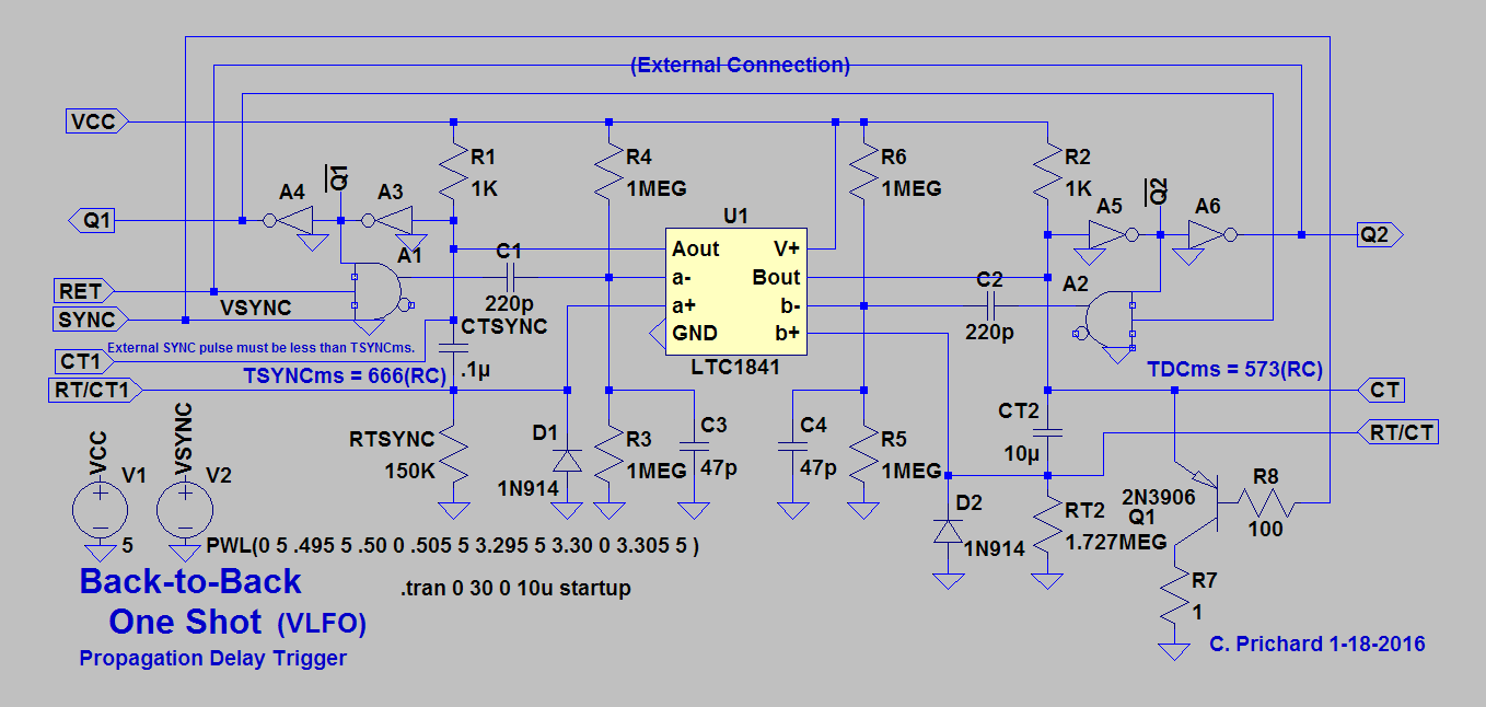
BTB1S Drawing is of an implementable version. Propagation delay puts a trigger on inverting input, driving comparator to runaway. Output charges timing capacito. Not sure how it discharges... this can actually be implemented.
ILC PROTO SOURCE CODE I added a software implementation of the DUMMY CARD feature. This code compiles, and will allow me to create a tool for tinkering with user interface with simple LED's and buttons. It will be possible to implement a program mode to adjust delays. Am thinking to try thumb-wheel resistor setup... I will add some comments, and document the DUMMY implementation.
Am looking at software implementation of the DUMMY CARD for Arduino.
Briefly, it presents a user interface problem. Looks like a solution begs for an adjustable analog input value for each activated DUMMIED sensor. Is easy to call DCPRQ_update to update PRQ status if the delay is expired. This call would be in an if-else that determines if the DC option is in use. The function will require external values, and simply use them to return a result for each installed DC option. This is to determine downtime delay between PRQ requests. Example, it could be twenty minutes for the sensorless septic pump. The delay value could be adjusted with a voltage on one of the analog inputs.
In the function below, DC_ltime is read when a new DC_PRQ delay is begun. The time value is stored with the desired delay_PRQ value and are passed into the function to be used and compared with present time. Result is HIGH or LOW, and used to update the associated PRQ_State value.
int DCPRQ_update(unsigned long DC_ltime, long delay_PRQ ) {

	unsigned long ptime = 0;
	long Timer = 0;

	ptime = millis();
	Timer = ptime - DC_ltime;

	if (Timer >= delay_PRQ){return HIGH;}

	return LOW;

}
Another possibility is to provide the hardware DC option based on a 555 timer implementation. I worried that it might be difficult to implement the retriggerable 1SHOT, but a 555 can be used, retriggerable after the delay is expired....
Read more »


 andyhull
 Jamie
Jamie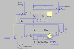
7-29-15 If anyone wants to contribute to this topic, I think this project merits being divided into two projects. One, simply offers the SPDT exclusivity to prevent two loads from being switched concurrently. The spin-off project is the prioritizing, or Inductive Load Center with the patentable hardware design using the PMUX in a PAL, and the back-to-back re-triggerable monostable concoction, as simulated. Another part of this project is to present a programmable development piece of hardware which can function as the Inductive Load Center, as well as other programmed devices, controlling any type of device.
Prioritization offers a way to allocate power to prevent overloading, The PMUX may be reprogrammed to provide other logic. Benefit of all this is that once understood, the device can be leveraged to work in combination with solar power, batteries, and inverters to provide adequate solutions to off-grid power systems that may include several inductive loads.
Option to implement the simple hardware solution, or to include processing and sensing of other input may interest a developer that sees potential to profit from production of a line of these devices, aimed initially at preventing concurrent switching, and overloading.
Once the spin-off project is created, it will receive more attention as it will include Arduino for the stated benefit to development of new applications...