 vysocan76
-
Realy nodes
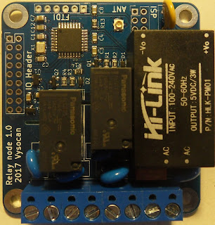
08/29/2017 at 08:15 • 0 commentsAfter some testing I have finished new relay node. As all nodes it is Arduino compatible board with ATmega 328P clocked at 16MHz@3.3V.
![]()
- Size 6.1 x 5.6 cm.
- On-board AC/DC power supply. Input 100-240VAC, 50-60Hz. Output 5V/3. Fused with TVS on input with slow blow 0.5A fuse.
- 2x Japanese(Panasonic) power relays with COM, NC and NO inputs. With TVS on both.
- It has more powerful RFM69HW soldered on back with IPX connector.
- Temperature sensor to indicate overheating based on MCP7900A on ADC6. It is mounted under AC/DC power supply.
- IO header, rest of pins are taken out. As well as +5V and +3V3 to add another relays or sensors.
- Programmable via standard FTDI 6 pin 3V3 programmer.
It is available in my online store. Schematic is in my shared folder, and example sketch is placed on GitHub.
Link to blog: http://openhomesecurity.blogspot.cz/2017/08/realy-nodes.html
-
SIM800 vs. SIM900
06/03/2017 at 07:55 • 0 commentsWell it actually looks like there are some differences in SIM800 comparing to SIM900. Echo and command routines are working just fine, but reply to SMS send function is different. SMS is actually sent, but the function is not able detect successful sent. There seems to be two reasons. First, the the rely looks little different. That is the echo of SMS text is not preceded with empty line and "> ", but there is simply one line with echo. Second, the reply time of SIM800 is significantly slower then SIM900. It looks like "CMGS:#", the acknowledgement of SMS, comes after the SMS is delivered to actual number.
First problem is relatively easy to solve, on beginning we cn ask GSM modem for the version and then branch the SMS send function depending on model. But the second must be investigated. I've seen some command that can make difference in how the SMS sending is handled, but the setting in SIM800 looks right., interesting :).
http://openhomesecurity.blogspot.cz/2017/06/sim800-vs-sim900.html
-
Blue gateway 1.7C
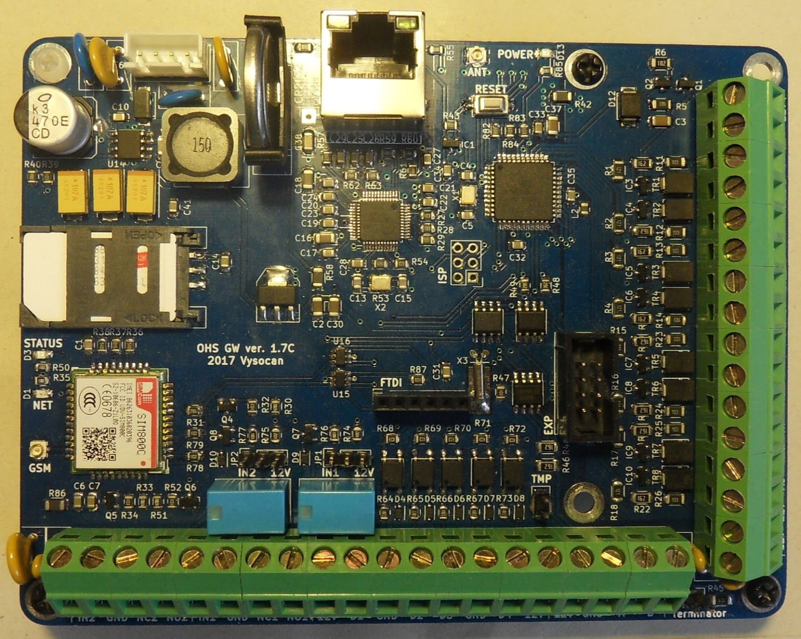
05/27/2017 at 19:12 • 0 commentsA picture is worth a thousand words. Here is new OHS gateway officially named 1.7C. Major difference comparing to 1.7. is 2G modem SIM800C. With four bands GSM support it can be deployed worldwide. And just one remark to relays, I have switched from black Chinese made Omron to blue one's made in Japan. They are slightly more expensive, but somehow cute and blue :). Link to blog.
![]()
-
Nodes
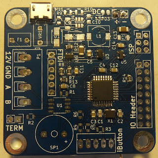
05/27/2017 at 05:26 • 0 commentsNew nodes now come with blue PCB and as option with USB charger. Here on picture you can see
![]() battery powered node with USB charging and temperature sensor. On back there is RFM69HW module, also available as option, and 720mAh Li-on battery. Such batteries can be found on ebay. They are sold for quadrocopter toys, and event they are labelled as 25C RC, they have build in protection circuit.
battery powered node with USB charging and temperature sensor. On back there is RFM69HW module, also available as option, and 720mAh Li-on battery. Such batteries can be found on ebay. They are sold for quadrocopter toys, and event they are labelled as 25C RC, they have build in protection circuit.Further more I will, or I can, equip all battery powered nodes with 8MHz crystal oscillator instead of 16MHz. This reduce the power consumption even more. The whole setup on picture has following consumption:
ATmega328P@8MHz sleeping 33.2~33.6uA
ATmega328P@8MHz running ~4mA![]()
Just to ones that are curious what are the missing components. This board can be either battery or DC powered, and also can communicate over radio(RFM69HW) or RS485.Link to blog.
-
Blue gateways
05/18/2017 at 10:20 • 0 commentsThe life of components in electronics can also come to an end. So is true about SIM900 GSM modem that is part of GW version 1.7. Although it is still available online, officially it is not recommended for new development, and local distributors have no longer any in stock. The decision had come to choose new GSM module. As SIMCom modules have proven to be reliable at good price, I had in mind to switch over to some of their new model. Put it simple SIM800C was chosen to be a replacement. It is still 2G modem with four band GSM support and can be deployed worldwide. Fortunately there is no difference in AT command set that is used by gateway firmware, so the new boards are interchangeable in terms of code. There seems to be interest in 3G modem of OHS gateway users that are located in U.S.A., but for now we stay at 2G (3G module is 4x expensive then 2G, and 3G band are varying across regions. But if there will be interest, I will design new version of gateway with possibility to mount 3G or 2G module).
New boards have also same footprint and connectors location have not changed, except for SIM card holder and GSM antenna connector. They are named 1.7C and come in blue colour with round edges similar to new nodes.
P.S. Picture will come soon :)
Link to blog.
-
Turning off gateway.
03/19/2017 at 21:05 • 0 comments![]() Some weeks ago I have decided to turn off older version of gateway (version 1.5) and replace it with new version 1.7. It was running for over a year and a half. Also it was not so easy as it used RFM12B radio module and all radio nodes need to be replaced as well. Well it is always at some cost to do upgrade, whether it is making of new nodes or time to put it together. But the time is here and I do not even remember how many changes and small fixes I done in transition to version 1.6. and later 1.7. But the old gateway has guarded my property good enough, with only one alarm, thankfully a false one. Caused simply by open window ventilation and hot summer wind. And as you can see on the picture on right the last update of firmware and accompanied reset was almost a year ago. Since then it was running and working without me noticing. I must once again thank NilRTOS for its stability. I have made a screenshot of the debug window, and there is clearly visible that the stack is rock solid.
Some weeks ago I have decided to turn off older version of gateway (version 1.5) and replace it with new version 1.7. It was running for over a year and a half. Also it was not so easy as it used RFM12B radio module and all radio nodes need to be replaced as well. Well it is always at some cost to do upgrade, whether it is making of new nodes or time to put it together. But the time is here and I do not even remember how many changes and small fixes I done in transition to version 1.6. and later 1.7. But the old gateway has guarded my property good enough, with only one alarm, thankfully a false one. Caused simply by open window ventilation and hot summer wind. And as you can see on the picture on right the last update of firmware and accompanied reset was almost a year ago. Since then it was running and working without me noticing. I must once again thank NilRTOS for its stability. I have made a screenshot of the debug window, and there is clearly visible that the stack is rock solid.![]()
Thank you and R.I.P. :)
Link to blog.
-
Battery node with USB charging
03/19/2017 at 15:55 • 0 commentsShortly after introducing rearranged PCB layout for nodes, I realized that I use LiPo batteries in all my battery powered nodes. That is making no use of the step up capabilities of the DC to DC converter. When designing it I was wanting to have possibility to run the nodes from variety of batteries. But it was never happened. In fact I have ordered some $3 to $5 LiPo batteries from eBay that supposed to be used for quadrocopters. These, although labelled RC 25C batteries, have battery protection electronic mounted on them (DW01+FS8205). My first happiness soon faded when I checked it does not stop the battery from under voltage. It will probably need some more investigation. Never the less, for the price, they seems like a nice choice for compact (43mm x 24mm x 9.5mm) power source and claiming ~720mAh of capacity (it really depends on supplier, ranging from 600 to 700mAh).
This led me to consolidation of what I use in case of LiPo powered node, and I ended up with new design of battery power circuit. I have taken out the DC to DC part and added low drop out linear regulator. MCP1700 with excellent quiescent current and drop voltage less then 200mV. I would lost the step up capability, but LiPo operate best in ranges of 4.2V to 3.4V as shown on the picture. Perfect match for such use. Taking a calculator in hand and the datasheet it revels, that the difference in terms of efficiency for LiPo battery is negligible. And in fact as the LiPo discharge it is more convenient to use liner regulator instead of switching, making it more energy efficient! Then single look on quiescent current makes the choice inevitable, linear consumes ~2uA while switching consumes ~80uA. That is 3 times more to what my ATmega328P@16MHz consumes while sleeping.
While having battery type set, it is much easier to choose charger circuity. Looking for easy solution I found MCP 73832 a single cell Li-Ion/Li-Po charge management controller. It is small footprint linear charger with charge current programmable by single resistor from 15 mA to 500 mA. Again datasheet stated very low standby current, and it seems to be used in many designs as Google reveals.
![]()
I ended up with new version of PCB and called simply node version 1.4. It has micro USB connector for power or charging and charge current set to ~450mA. With a rule of thumb of 1C charging current, it allow use of any Li-Ion or Li-Po battery with capacity bigger then 450mAh. It has no load sharing, but sleeping ATmega is not a problem. I have switched to blue solder mask colour and it is alrady tested and available for sale in my online shop.
I have measured power consumption in various stages to see how it behaves. Where there is range present it is difference between 3.5 and 4.2 input voltage.
... more on blog.
-
Relay nodes
02/10/2017 at 15:01 • 0 commentsLately I started prepare mains powered relay board. It will sports 100-240VAC switching power supply delivering 3W at 5V. Then two 10A relays, rest will be as usual ATMega328P with RFM69 receiver. PCB design is almost ready and as soon as I get all parts I send it for fabrication. Size will increase to 56*58mm to accommodate all new components. There will be possibility to have onboard thermometer and switching power supply monitor to detect overloading.
![]() Link to blog.
Link to blog. -
Loose antenna connector
02/08/2017 at 15:00 • 0 commentsDoing some experiment on my testing gateway I have put new pigtail on. I like to leave the SMA connector little loose, as it sits on table and is able to lay down completely when I move it. Staring gateway up, I was not able get response from nodes located further away. And I started to check if automated power level feature implemented in RFM69 library is working properly. ... It ended up that I have added new sensor type in gateway as well as the example sketches for radio nodes called TX Power. It shows the current TX power setting out if possible 32 levels present in RFM69 chips, and translate them into 3-100% float value transmitted to gateway. I did not put 0-100% as 0% made me little worried :) Bellow is picture presenting data from my testing meteo node, now with TX Power level.
More on blog...
-
New nodes
01/22/2017 at 11:00 • 0 commentsThere is now new board available called Node 1.3. It is small evolution of previous version 1.2. Mainly there are changes in IO Header pinout and possibility to add thermometer based on MCP7900A. MC7900A is linear active thermistor IC. That is analogue temperature sensor that converts temperature to analogue voltage. It’s a low-power sensor consuming 6 μA (typical operating current). And with little bit of calibration at room temperature it can provide ±0.5°C from 0°C to +70°C accuracy. Other then that some labelling was added and footprint of RS485 connector have changed.
![]()
Home security
Home security project based on atmega and ardunio. MQTT gateway for data gathering.
 battery powered node with USB charging and temperature sensor. On back there is RFM69HW module, also available as option, and 720mAh Li-on battery. Such batteries can be found on ebay. They are sold for quadrocopter toys, and event they are labelled as 25C RC, they have build in protection circuit.
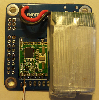


 Link to