Rui Rex
-
It's working!
08/26/2015 at 14:29 • 0 commentsI've assembled the last bits and it's working! :)
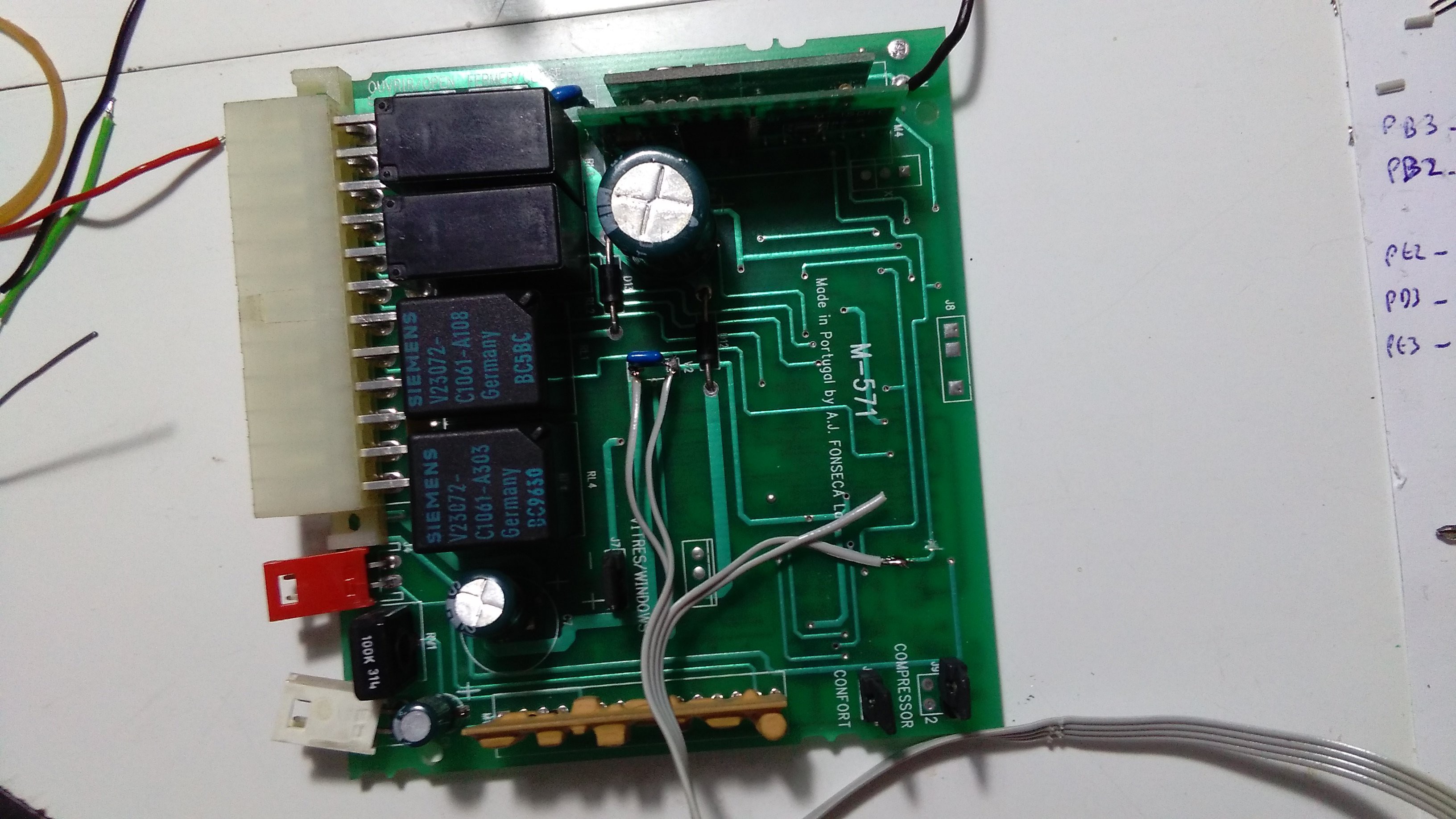
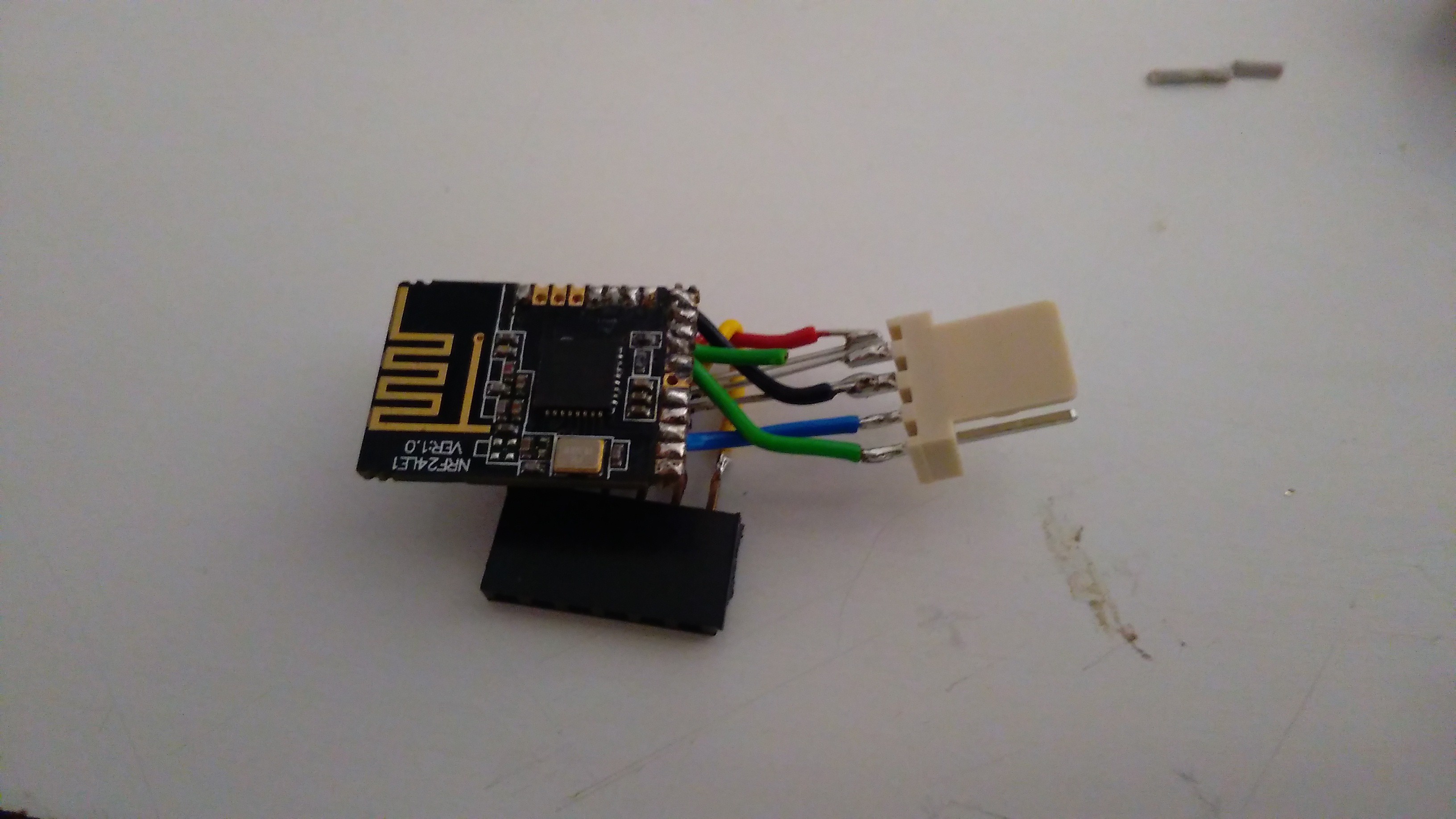
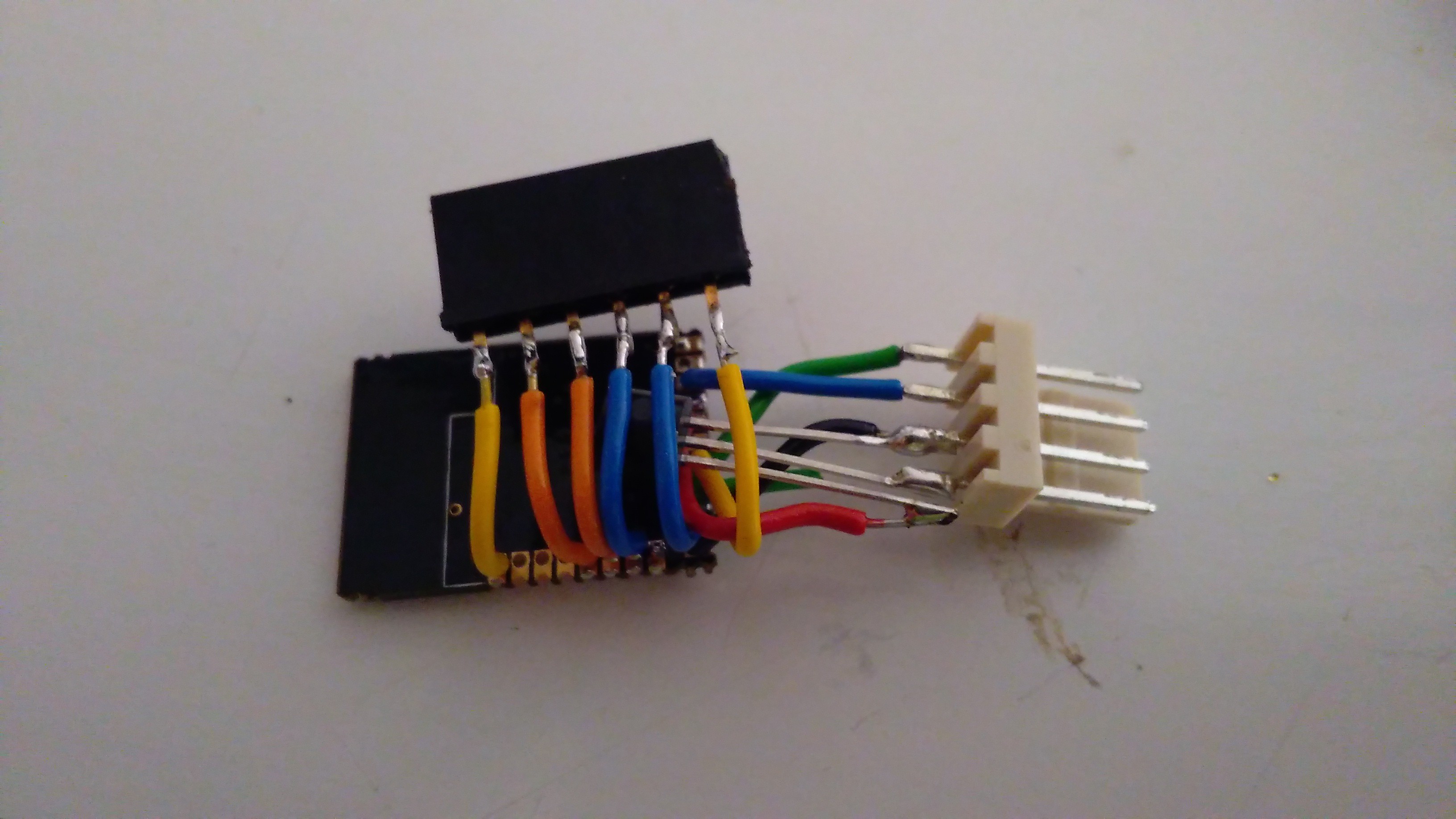
First I've cut the power and data lines on the RF module of the alarm so it won't draw unnecessary current and to allow the new module to drive the microcontroller input pin.
Then soldered the Groung, +5V and data wires to the corresponding places. The power pins on the capacitor at the output of the regulator and the data on a via near the PIC.
Lastly I've glued the wires to the board with hot glue so they wont get easily disconnected.
![]()
After this I assembled it on the car and voila! It works.
But then I found that only one of the signalling light output relay is working! Forgot that this gone bad just before the RF module gave away. And worst, it's the driver side that gone bad so it's harder to see when it received the command signal. I'll address this later.
The main issue that I found (and I was sort of expecting this but hoping it won't be an issue) is that the range s#cks! It's 1, 2 or at best 3 meters, depending on the angle horizontally and vertically. This is because the receiver sits inside the dashboard and the doors shield the signal. Because the cable is a bit short I can't rise it more (my fault!) but I'll get an extension or solder a new one. I'll try to put it on top of the cluster, this way I'll get a clear view of it from almost all angles and maybe this will solve the problem. Must make some tests.
I'm evaluating the possibility of discarding the microcontroller on the alarm board and all the remaining circuitry (ultrasound drivers, etc) and connect the Nrf pins to the relay driver and implement the alarm functions on it. This because the standby current is about 20mA! This is way too much for me. I suspect that replacing the 7805 for a more efficient DC/DC converter will make this better but if I get the PIC out it would be even better :)
P.S. 1 Lacks a video of it working. I'll address that soon...
P.S. 2 The key fob has arrived! Must have a look at it.
-
Until the new key fob arrives...
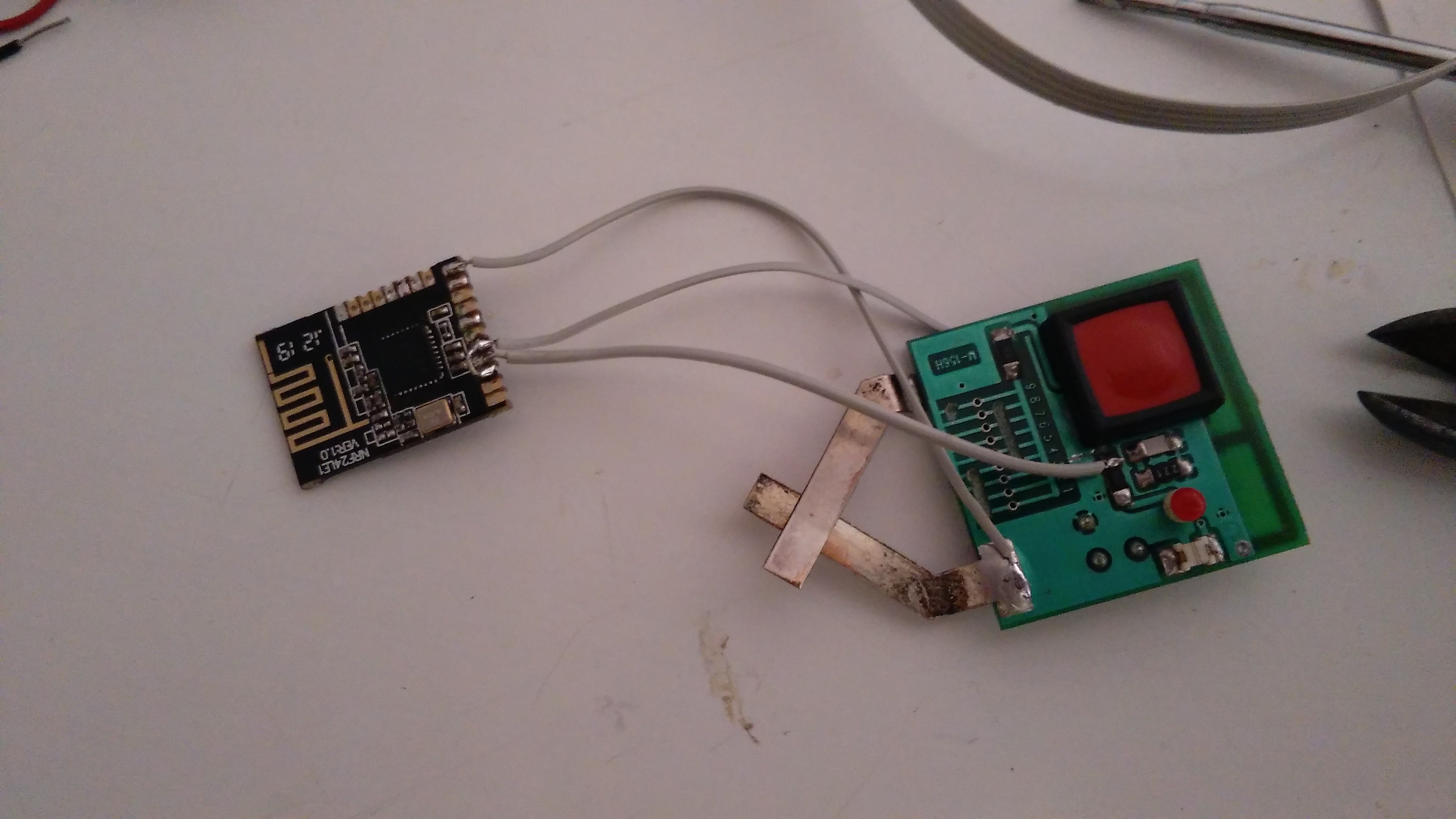
08/19/2015 at 09:18 • 0 commentsUntil the new key fob arrives I assembled the receiver and managed to get the transmitter board inside the old remote.
I've repurposed the existing button and the led to make the remote work.
![]()
The original setup uses 2 CR2032 lithium bateries. As I only need one, I removed the other and tighten up the contacts and found enough room to fit the Nrf24LE1 board! Yes!
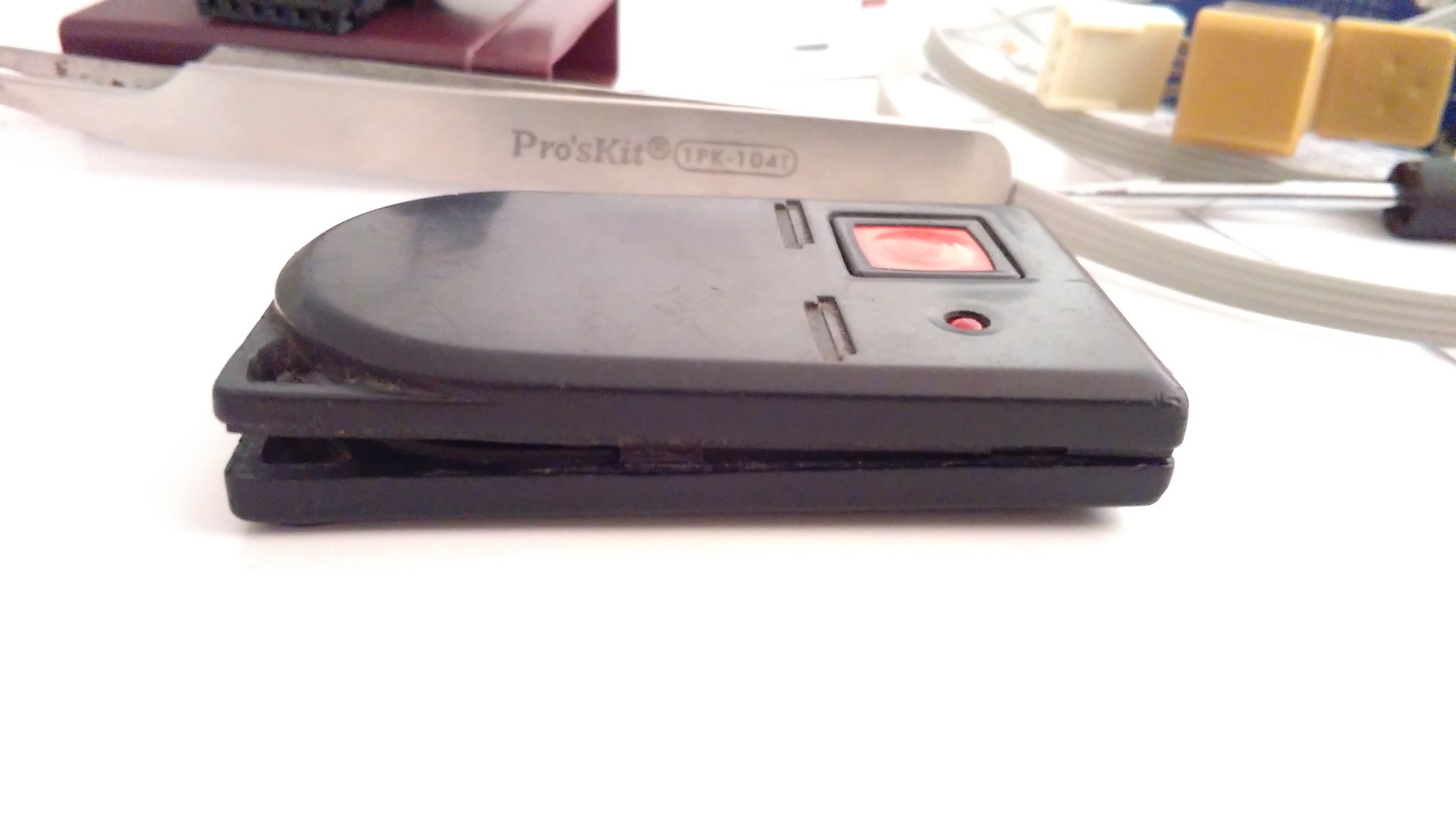
It's a (very) tight fit but it holds :)
![]()
I've made a simple test with the receiver and it works. Now I have to connect it to the alarm. It's a more sensitive operation as I use the car almost every day and can't mess this up or the car wont start :).
![]()
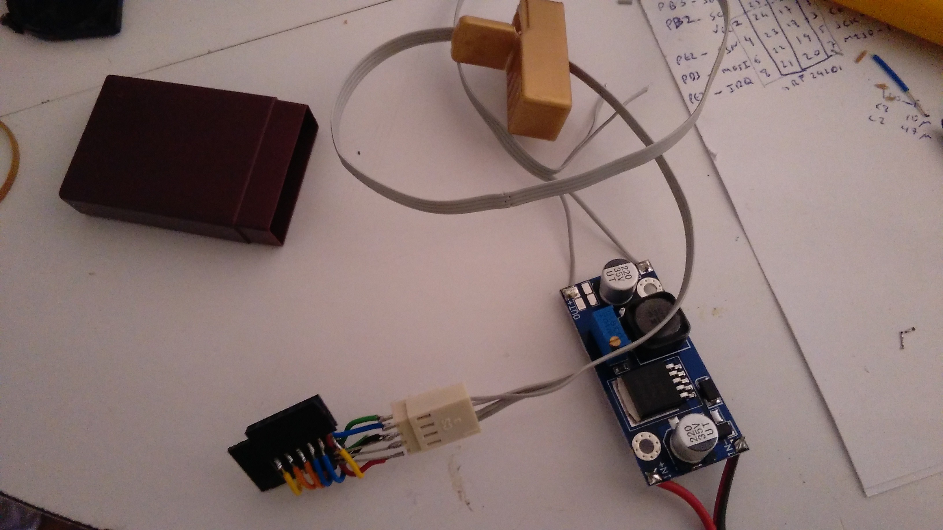
Added two connector ports, one for normal use and one for programming in case I want to make a firmware upgrade :)
![]()
![]()
-
New Key Fob
07/23/2015 at 13:19 • 0 commentsI was navigating through ebay and I remembered that there are a replacement key fobs that are really cheap and would be perfect for my project!
This way I didn't need to design a new box or fit the electronics on the old remotes!
And more! I can make a copy of the ignition key and get a identical setup to the more modern versions!
Here's a photo of it:
![]()
I don't need the 3 buttons but I'll find a use for the trunk one :) panic button maybe?!?
My setup uses only one button as the alarm only uses one signal line for the open and close command. Maybe later I'll change the alarm microcontroller and make my own version... but for now this is the way :)
-
Power considerations part 2
07/08/2015 at 09:13 • 0 commentsMy estimates (by thumb rule) where a bit pessimist.
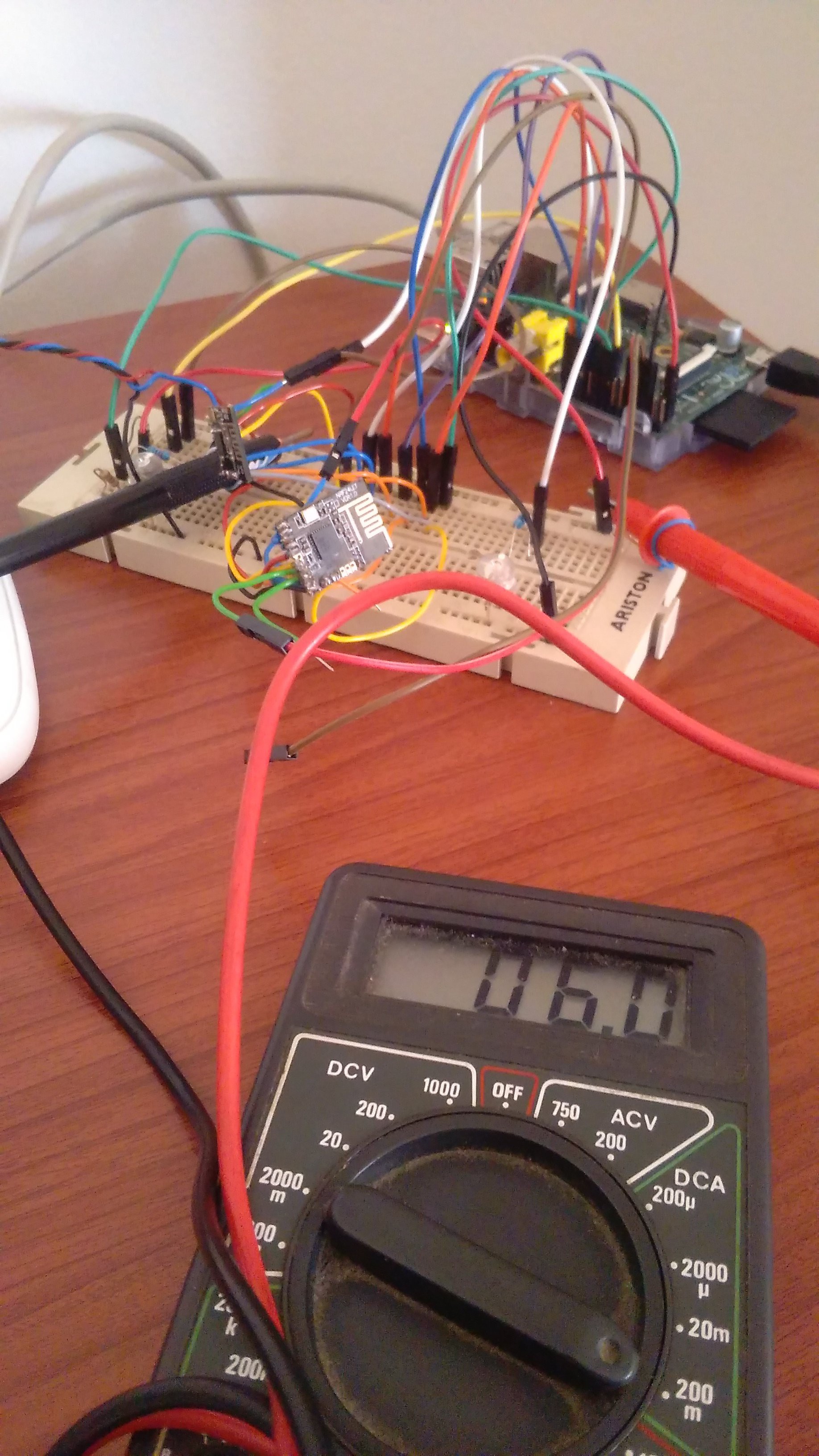
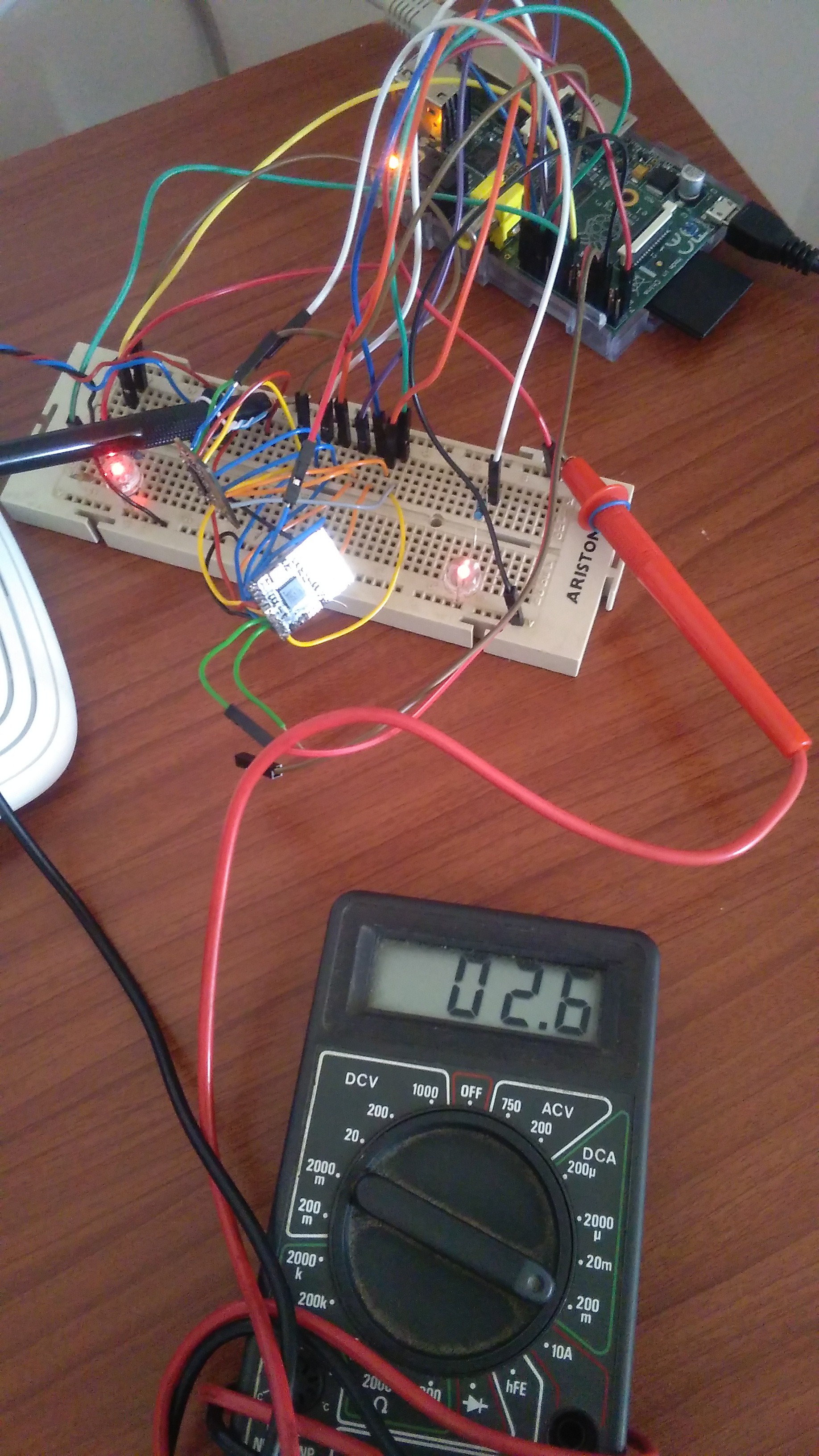
So, I got an average of 6mA standby current on the receiver module and only 2.6mA active current on the transmitter! This enables a much longer battery life!
The receiver standby current:
![]()
The transmitter active current:
![]()
P.S. don't mind the dusty multimeter :) It's been a while since he was last used.
-
All about power...
07/01/2015 at 08:29 • 0 commentsRunning the modules at full speed (16MHz) and adding the current consumption of the radio blocks on the TX and RX modules I noticed that the receiving will cause a lot of battery drain:
RX: ~13mA (radio) + ~9mA CPU = ~22mA
TX: ~11mA (radio) + ~9mA CPU = ~20mA
So I've dropped the CPU frequency to 1MHz and "PWMed" the radio block disabling it for a period of time (around 150ms) and enabling it for a short period (~50ms). This will enable a power saving around 75% on the radio alone. The CPU will drop to around 1mA making the total current of :
RX: ~4mA (radio) + ~1mA CPU = ~5mA
This is more acceptable.
The 12V rail current drain will be even lower as the switch mode power supply will draw less than that from the 12V.
I'm going to make some real measurements and post them here.
On the TX side I've also applied this power saving scheme but I had to apply less "off time" to avoid having to press the button a long time for the receiver to acknowledge the signal. It's about 33% off time. but I'll also try to lower the TX power so I can get aditional savings.
TX: ~8mA (radio) + ~1mA CPU = ~9mA
A CR2032 battery has around 240mAh of capacity so this results in 26hours of remote module autonomy.
Assuming a average button press of around 3 seconds (will be lower than that but still) this gives an autonomy of 31200 button presses.
No problem here, I gess :)
-
Houston, we have touchdown
06/15/2015 at 12:19 • 0 commentsBased on the code used on the key fobs from this site: http://store.diyembedded.com/index.php?main_page=product_info&products_id=31
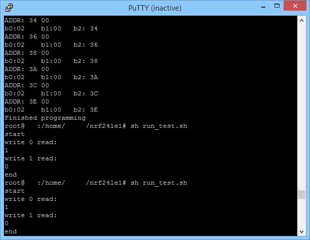
I've compiled the code, sent it to the modules and voilá! I can decode the keys sent.
![]()
The keys are emulated by the Pi's GPIO's. I've used one pin as output for the transmiter and one as input for the receiver. This way I can change the state of the tx pin and see if the rx pin changed as well. This way I can check remotely if the code and the modules are running as planned.
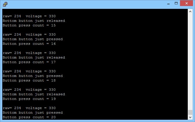
Also, I'm sending the battery voltage on the data frame. This way I can get a warning from the car when the voltage gets too low.
![]()
-
First step (part two)
05/26/2015 at 08:21 • 0 commentsNow connect the two modules to the Raspberry Pi.
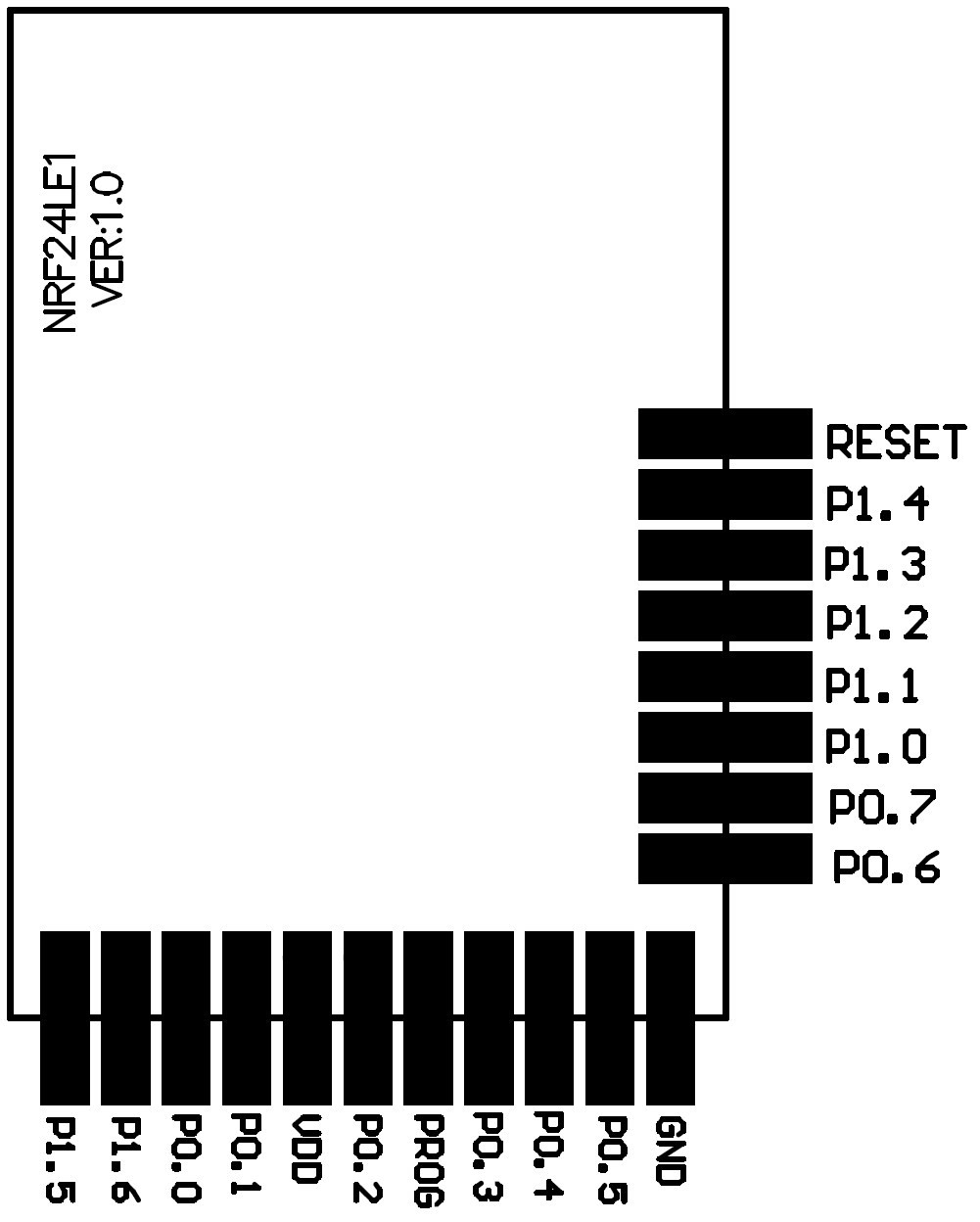
I'll make a diagram of the connections but meanwhile I'll leave the list of connected pins (this module uses the 32 pin version):
nRF24 - Raspberry GPIO
FCSN (P1.1) - 8
FMISO (P1.0) - 9
FMOSI (P0.7) - 10
FSCK (P0.5) - 11
PROG - 24
RESET - 25
Finally, the GND and 3.3v and that's it.
![]()
Also, on the Raspberry, download the necessary libraries, SDK and some examples:
This page has the necessary information although some bits are not quite well explained but you can get the big picture:
http://sysmagazine.com/posts/210974/
Also has a code example "led_delay" that will blink a led on pin P0.0. This helps to test the programmer and then compilation platform.
-
First step: Building a test platform.
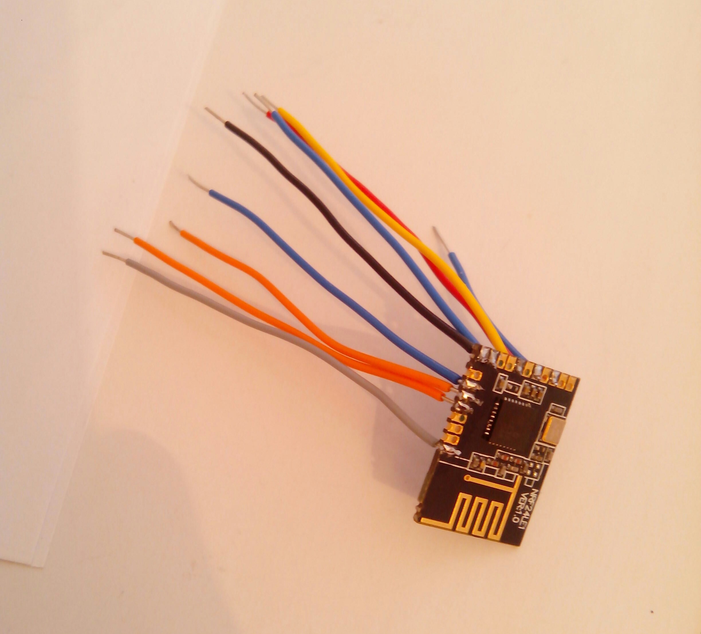
05/25/2015 at 10:59 • 0 commentsSolder some wires to the modules so that I can connect them to the Raspberry Pi to upload some magic code!
(having some issues with image upload...)
![]()
Car alarm secure remote with nRF24LE1
My car's alarm remote went dead. Now is the opportunity to implement a safer and more reliable remote for it using nRF24LE1.