shlonkin
-
Final result - it is complete
04/27/2014 at 14:33 • 0 commentsI hope that at this point you have read enough description in the project logs that I don't have to go into too much detail here. Rather, I want to show you a video of the complete stargate in action. In this video there are two ends of the wormhole, one in Utah and one in Japan. On one end is the stargate and it's remote dialer. On the other end is a dialing computer simulator. First in the video the gate end dials and the simulator receives, then the other way around. The motion/animation and sounds occur simultaneously on both ends, but due to video editing issues, things may not sync well in the video.
Here it is: http://youtu.be/ZCM7bWPBwMM
With this result we have accomplished what we set out to do, though it would have been nice if we had time to build a second gate for the other end. Each of the three team members contributed a vital portion of the project as follows.
Brando - extracted and processed the sounds from stargate videos
dkopta - wrote all of the software running on the computers
shlonkin - built the physical stargate and electronicsAlso, we have tried to share all files, schematics and build details, but if you find something missing, or if you want some specific info, please leave a comment and I'll do what I can.
Thanks
-
Software - first contact and all the files
04/27/2014 at 14:26 • 1 commentThanks to team member dkopta the stargate has now established a connection across the vastness of space... er, I mean the internet, to a computer on the other side of the world. On the other end was an awesome stargate simulator, or rather a dialing computer simulator, made by dkopta. We also need to thank a new team member, Brando the audio technician, who extracted the audio from some SG-1 videos to acquire some high quality gate sounds. We really wanted to have a second gate on the other end, but there was no way it could be completed in time for the contest. At this point the only data transmitted has been the dialed address itself so that the receiving end can simultaneously move and play sounds. Dialing and receiving can go both ways, so I can feel the fear of an incoming wormhole with no iris on the gate. Fortunately no goa'uld have come through the gate yet.
Anyway, on to the details. There are actually several bits of software in use.- The microcontroller code written in Arduino
- Processing sketches that interface the serial connection from the mcu to the internet
- a dialing computer simulator on the other end(because we didn't have time to build a second gate)
- and a server that acts as a hub between connecting computers.
First, the arduino code, which can be found here:The ATMega328 listens for input from a serial connection as well as an IR receiver. If there is IR input, it enters dialing mode in which it receives an address from the remote dialer(described in a previous log) and sends the corresponding data to the computer. That data includes the indices of the glyphs being dialed and the number of glyphs that must be rotated to get there, which is used to determine timing for the sounds. Those numbers are both sent to the receiving computer so that sounds and such can occur simultaneously on both ends.
If there is serial input, the gate enters receiving mode in which it receives glyph indices and sends the timing info described above. In both modes the mcu controls the stepper motor rotating the ring as well as the chevron LEDs.
Second, the Processing code on the gate end, which can be found here:There are separate programs for dialing and receiving, though it would not be too difficult to combine them into one. These programs are responsible for connecting the mcu to the internet and playing sounds. They get sound timing info from the gate(serial) and piece together rotation startup, rotation, and chevron engaging sound files that can be found here:
Third, the dialing computer simulator, which can be found here:
Since there was not enough time to make a gate for the other end of the connection, dkopta put together this nice animated simulator. Rather than a lengthy, unclear description of it just go watch the video of it in action, which is included in the final result log. It works for both dialing, by clicking the symbols, and for receiving.
Fourth, the server code, which can be found here:This was set up on another computer for convenience and testing. It basically manages the connection and relays data.
-
Hardware - remote dialer
04/25/2014 at 13:33 • 0 commentsThe contest is coming down to the last few days and the stargate is nearly complete. The gate itself is fully functional and is embedded in a stand. The software being written by dkopta now works, but needs a little more debugging. dkopta has also finished the audio part of the project(i.e. it plays sounds when the gate rotates and when chevrons engage). I will post another log tomorrow showing the nearly finished state of things and hopefully a short video of it in action. The code will also be available once it is finalized.
I have also put together a remote dialer, which I introduced way back at the beginning. It's based on this wireless 10-key:
![]()
It looks pretty much the same, but I painted the front bezel to match the gate and cover the label. Unfortunately, the electronics inside were not functional, so I gutted it and stuck in an ATMega328 microcontroller to read the keypad and control an IR LED. Here is an annoyingly small version of the schematic.
![]()
Here is the code:
https://drive.google.com/file/d/0B0-PE-lARnk1WWwyUGUydGx2S2c/edit?usp=sharing
-
Hardware - light and motion test
04/19/2014 at 10:29 • 2 commentsHere is a short video showing the current state of the gate.
https://www.youtube.com/watch?v=JfeqSvm70j0
(Can I embed videos somehow?)
and a picture
![]()
As you can see, the internal ring is turning alright, but it does sometimes get momentarily stuck on a poorly shaped tooth and skips a few steps. This messes up the symbol alignment, but it's not devastating. In the video it is simply turning back and forth with increasing angle.
The lights look great. They came out better than I was expecting. The light is nicely diffused by going through a couple layers of textured translucent plastic. I just scraped the paint off where I wanted the light to come through.
The smd LEDs were soldered to thin enameled wire salvaged from a motor. The wires were routed around the edge of the gate and hot glued in place. Here is the rats nest of soldered up LEDs followed by a much more orderly picture of them attached.
![]()
![]()
You can see the breadboarded circuit in the top picture. Here is a rough schematic. I wish I could put a larger version here.
![]() Of course I will post the code here when it is finalized. The next steps include setting up the IR communication with the remote dialer, putting it in a proper stand that conceals all the stuff on the bottom, and getting some software made for the internetting side side of the project. Team member dkopta is working on the software, but it is not ready yet.
Of course I will post the code here when it is finalized. The next steps include setting up the IR communication with the remote dialer, putting it in a proper stand that conceals all the stuff on the bottom, and getting some software made for the internetting side side of the project. Team member dkopta is working on the software, but it is not ready yet. -
Hardware - Moving parts are moving
04/17/2014 at 13:48 • 0 commentsFor the last couple weeks I have been doing battle with the rotating ring. I was expecting it to be a challenge, and it sure is, but it's finally coming together. At this point the internal ring does rotate and the chevrons light up.
The internal ring has to rotate precisely and reliably to put the right symbols in the right place. This means either a stepper or a servo. I chose a stepper because I have a box of salvaged ones waiting to be used and I am more familiar with them. But then I have to figure out how to couple the motor to the ring. The following picture shows my solution.
![]() Yes, those teeth were cut by hand with a utility knife. There are hundreds of teeth. It was a painful and maddening process. There are a couple places where the teeth were just slightly too big and the motor does not mesh well, but tests have shown that it still still rotates without much skipping.
Yes, those teeth were cut by hand with a utility knife. There are hundreds of teeth. It was a painful and maddening process. There are a couple places where the teeth were just slightly too big and the motor does not mesh well, but tests have shown that it still still rotates without much skipping.I then needed a way to keep the motor in contact with the ring. The obvious answer was to remake the gate so that the motor could be mounted directly to it. This cutting board was chopped up to make a new back layer with a tab for mounting the motor.
![]() I then wanted to improve the bearing surface against which the rotating ring will press. I tossed the inner spacer and made a new one in a very different way. First I used scissors cut thin strips(3mm and 7.5mm) of 1.2mm polypropylene. I then wrapped them into circle placing the ends together like so.
I then wanted to improve the bearing surface against which the rotating ring will press. I tossed the inner spacer and made a new one in a very different way. First I used scissors cut thin strips(3mm and 7.5mm) of 1.2mm polypropylene. I then wrapped them into circle placing the ends together like so.![]() Then I used my handy homemade foam cutter to melt the ends together, welding them. This produced a very smooth, round ring for the rotating ring to press against.
Then I used my handy homemade foam cutter to melt the ends together, welding them. This produced a very smooth, round ring for the rotating ring to press against.![]() Oh, and here's the foam cutter if you wanted to see it. I had to go beyond the foam cutting settings to get hot enough for this plastic.
Oh, and here's the foam cutter if you wanted to see it. I had to go beyond the foam cutting settings to get hot enough for this plastic.![]() Once I had the pieces all made, I stuck them together and fought with it for a few days to get it moving. Here it is without the front layers attached. Notice that the rotating ring is painted.
Once I had the pieces all made, I stuck them together and fought with it for a few days to get it moving. Here it is without the front layers attached. Notice that the rotating ring is painted.![]()
![]() To keep the gears meshed nicely, a spring pulls the motor up and one of the mounting screws rides in a slot.
To keep the gears meshed nicely, a spring pulls the motor up and one of the mounting screws rides in a slot.![]()
Well, that wraps up this log. I know I mentioned that the lights are working, but I have to go to bed, so you will have to wait a day or two for that update.
-
Hardware - all layers cut, test fitting
04/05/2014 at 13:16 • 0 commentsIt's finally starting to look like a stargate. I finished cutting out all the plastic pieces, like these chevrons here:
![]()
I then tried fitting everything together. Of course nothing was perfect the first try, so I carefully shaved down the imperfections till the rotating ring moved freely. Here is a rough diagram of the assembly. It consists of four layers stacked like so. You can see that the back is closed and undecorated, but hey, that's how they made the actual prop in SG-1. They never show the back of the Earth gate for a reason.
![]() And here are some pictures of the layers just sitting on each other, not attached. Trust me, it will look a lot better when it is cleaned up, painted and illuminated. But before I do that, I will work out the ring moving mechanism. I'll update again after I get things moving.
And here are some pictures of the layers just sitting on each other, not attached. Trust me, it will look a lot better when it is cleaned up, painted and illuminated. But before I do that, I will work out the ring moving mechanism. I'll update again after I get things moving.![]()
![]()
-
Hardware - chevrons, glyphs and other details
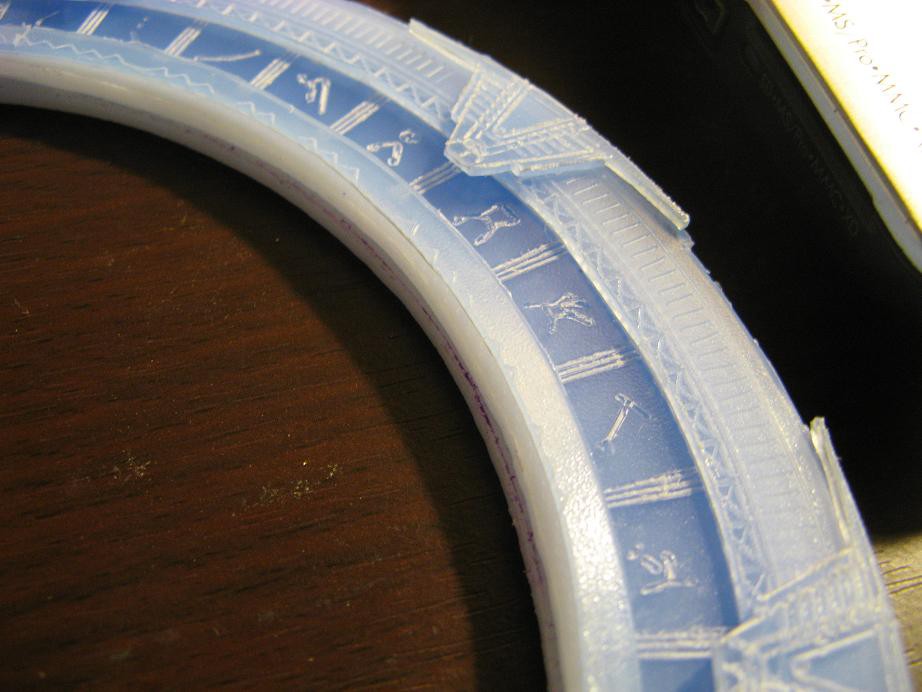
04/01/2014 at 13:56 • 4 commentsI was scratching my head, wondering exactly how I was going to make the fine details like chevrons, glyphs on the rotating ring and other patterns. Then I looked behind me and saw the pcb mill I have been working on. What an obvious solution. I had a 1.2mm thick sheet of polypropylene that fits just great in the mill, so I gave it a try. Here are the results as seen from the front and lit from behind. They need some deburring, but I'm very pleased with the result. Now I just need to cut them out, paint them, and assemble them with the rest of the parts. I will use the same technique for all of the decoration on the other parts, too.
![]()
![]()
And here is a close shot of the Earth glyph
![]()
Here are the .svg files that were used. I made them in Inkscape by tracing over the stargate picture.
- rotating ring
- chevrons
- front layer (may be modified later)
I have also made some changes to the materials used. After making lots of plastic rings and playing around with them, I have decided to use 3mm for a back layer, 3mm for the middle spacers, two pieces of 1.2mm(thus 2.4mm) for the rotating ring, 1.2mm for the front layer, and 1.2mm for the chevrons. All pieces are polypropylene.
-
Hardware - materials
03/29/2014 at 14:03 • 4 commentsIt's been a slow beginning, but I'm finally finding some time to start making the physical gate. Here are some basic specs:
- Outer diameter is 19cm
- Material is HDPE and polypropylene
- It is built in four layers: back, spacer/rotating ring, front, chevrons
- It does not exactly match the shape of a real gate because I do not have the tools or time to make such a perfect replica. But I will do my best to match the appearance.
The basic material, the plastic, is sourced from dollar store cutting boards... Wait, don't walk away just yet. It's a perfectly reasonable source of flat plastic sheets, and hey, it makes the project a better educational example for young(or poor) hackers who don't have 3D printers or money.
Anyway, I was planning on just using HDPE because it is so easy to cut smoothly and I've had good experiences with it. I ended up getting some polypropylene boards too because they were the thickness I wanted. It is also pretty nice to work with, but a little more brittle. That means if I put too much pressure on a knife cutting a delicate piece, the plastic might suddenly break and destroy the piece.
Here are the boards. One is already in the process of being cut. Their thicknesses are 3mm, 4mm, 6mm.
![]()
The design is based on an image from the wikipedia page. I used Gimp to make some rough guides for cutting then printed the image so that the outer diameter is 19cm.
The cutting began with the spacer layer, which is 6mm thick. I just need two simple rings, but they are thin and need to be pretty accurate. I glued the printed image to the board, carefully cut the paper into ring shaped stencils, then used a black crayon to color the plastic to be removed around the rings. Using this a a guide, I cut the board as carefully as possible with a jigsaw. Here it is partially cut. The thing I'm holding is one of the paper stencils.
![]()
I also made some first attempts at the much more intricate chevron pieces. They will certainly take some patience and I don't have any useful result to show yet. I'm thinking of investing in a rotary hand tool like a Dremel.
As a side note, I'd like to make a remote dialing computer. I won't make a DHD(dial home device) replica because of time constraints, but the Earth gate that I'm copying didn't have a DHD anyway. Stargate command used a dialing computer. It will be based on this awesome garbage find, a wireless 10-key.
![]()
- Outer diameter is 19cm
A functional Stargate
It won't transport me, but it will transport something across vast distances


 Of course I will post the code here when it is finalized. The next steps include setting up the IR communication with the remote dialer, putting it in a proper stand that conceals all the stuff on the bottom, and getting some software made for the internetting side side of the project. Team member dkopta is working on the software, but it is not ready yet.
 Yes, those teeth were cut by hand with a utility knife. There are hundreds of teeth. It was a painful and maddening process. There are a couple places where the teeth were just slightly too big and the motor does not mesh well, but tests have shown that it still still rotates without much skipping.
 I then wanted to improve the bearing surface against which the rotating ring will press. I tossed the inner spacer and made a new one in a very different way. First I used scissors cut thin strips(3mm and 7.5mm) of 1.2mm polypropylene. I then wrapped them into circle placing the ends together like so.
 Then I used my handy homemade foam cutter to melt the ends together, welding them. This produced a very smooth, round ring for the rotating ring to press against.
 Oh, and here's the foam cutter if you wanted to see it. I had to go beyond the foam cutting settings to get hot enough for this plastic.
 Once I had the pieces all made, I stuck them together and fought with it for a few days to get it moving. Here it is without the front layers attached. Notice that the rotating ring is painted.
 To keep the gears meshed nicely, a spring pulls the motor up and one of the mounting screws rides in a slot.

 And here are some pictures of the layers just sitting on each other, not attached. Trust me, it will look a lot better when it is cleaned up, painted and illuminated. But before I do that, I will work out the ring moving mechanism. I'll update again after I get things moving.