-
Board Revision Planning
06/30/2015 at 02:22 • 0 commentsSo I'm currently trying to decide what to do next with this project. I have a few other projects floating around that have taken priority (such as collaborating with someone who's building something based on my ESP-01/03 Breakout), and work and travel have gotten in the way recently.
My current thought is to fork my effort, and create two simultaneous layouts with different timeframes:
- Minor revision: only change the footprint of the blasted PCM2706 that gave me such soldering adventures last time. This will be an easy fix, but I run the risk of the board still not working because I haven't isolated the problem.
- Major revision: complete redesign. Reexamine all the circuit components, layout, and logic, to confirm that everything is wired right, and that there are no better parts for the job that could reduce my circuit complexity.
- For example, a high quality USB DAC chip that could output great signal straight from the chip itself (would replace both PCM2706 & PCM1794).
However, forking will greatly increase cost, as each current run of boards will cost $30 at OSH Park (2"x3" board = $5*(2*3)=$30 for 3), and the parts in the BOM costs roughly $60 each, running to $90 for each iteration of the board (assuming I don't retrieve parts off the outdated boards, which is hard without a hot air gun).
The better solution would be to order a set of parts that I think I will use, and a bunch of SMD to breadboard breakouts, and try to wire everything up in a breadboard to confirm that it will actually work before I layout & order the board. This has the advantage of enabling troubleshooting & reconfiguring of the circuit, but at the expense of complexity, a large breadboard needed, and
My least favorite option, but maybe the best to fit within my life, is to simplify the board, and just use the first-stage PCM2706 into the opamp. This would prove that the opamp and PCM2706 are working, and have a higher chance of success. It would also be simpler, which will allow me a quicker turnaround time and to fit it between my other projects.
If anyone has any opinions, please let me know! I'm currently leaning towards cutting features and getting the PCM2706/opamp combo working on a smaller board, and then trying to get the PCM1794 added in after that's working.
-
Schematic v1.0
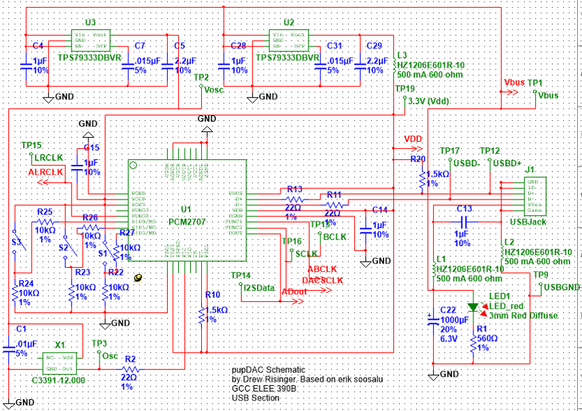
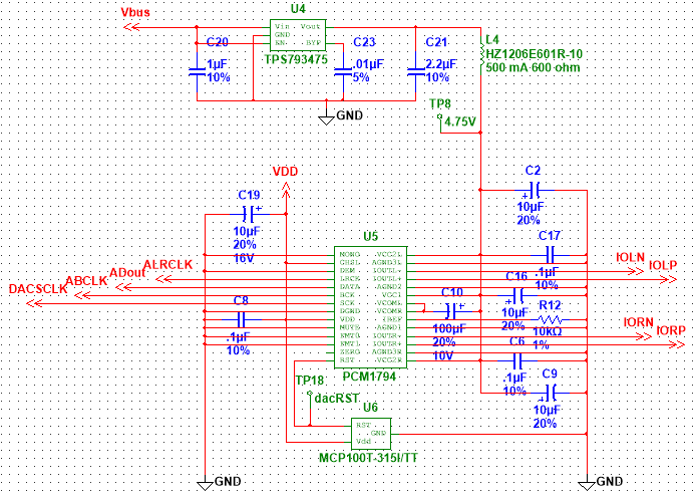
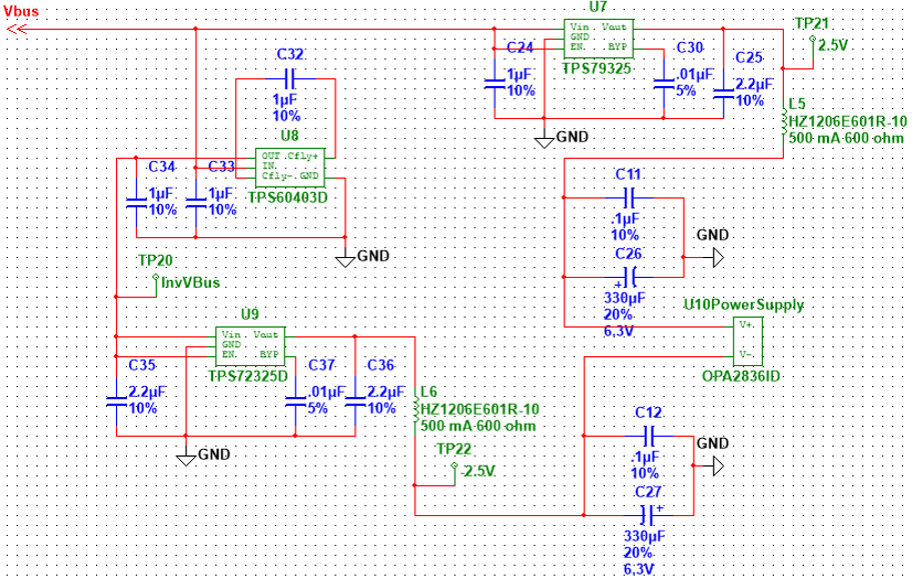
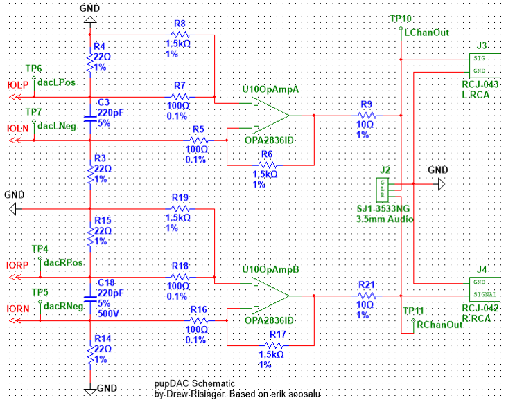
05/28/2015 at 05:44 • 0 commentsThis is the schematic that corresponds to version 1.0 of my design. It's divided into 4 sections: the USB section (which takes USB signals in, and outputs I2S Data), the I2S DAC (which outputs a balanced audio signal), the output opamp power supply section, and the opamp circuit itself, which provides the output.
USB Section
![]()
I2S DAC
![]()
Opamp Power Supply
![]()
Opamp Audio Output
![]()
-
Constructing the Case
05/28/2015 at 05:25 • 0 commentsI was really fortunate to have access to my school's manufacturing equipment in constructing my case, even though I'm an Electrical Engineering major.
I was able to construct a case in two parts, with some assistance on the CAD side.
![]()
Bottom Part
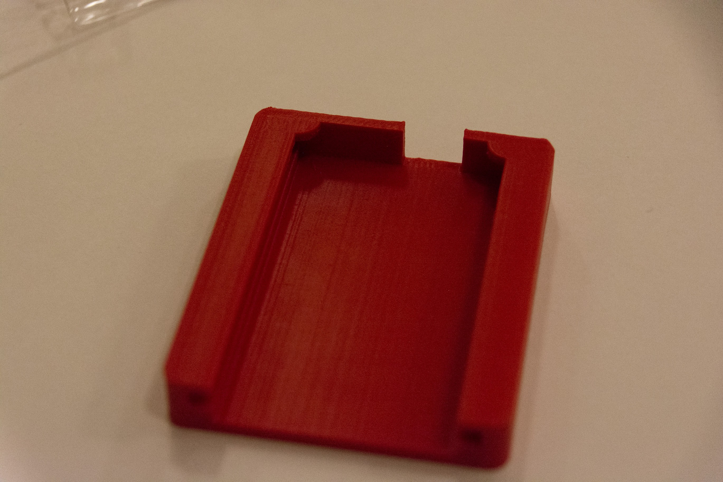
The 3D printed bottom.
![]()
This is a fairly simple part, just printed on a 3D printer. The circuit board slides into a slot beneath the top edge, and there's an opening on the back edge for the USB port. While the tolerance for the height of the circuit board opening could've been lower, it wasn't bad for a rev 1.0
Top Layer
The top layer was made from vacuum-formed plastic (or thermoformed, depending on who you ask).
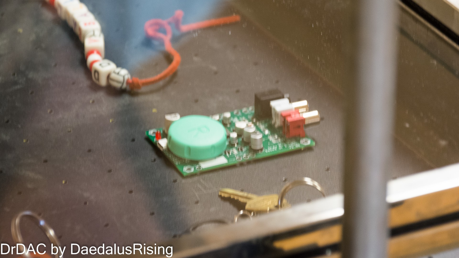
![]() The bubble on the right was made by a contact lens cover, which served to protect the delicate soldering work of my problem IC from being destroyed in the vacuum-forming process.
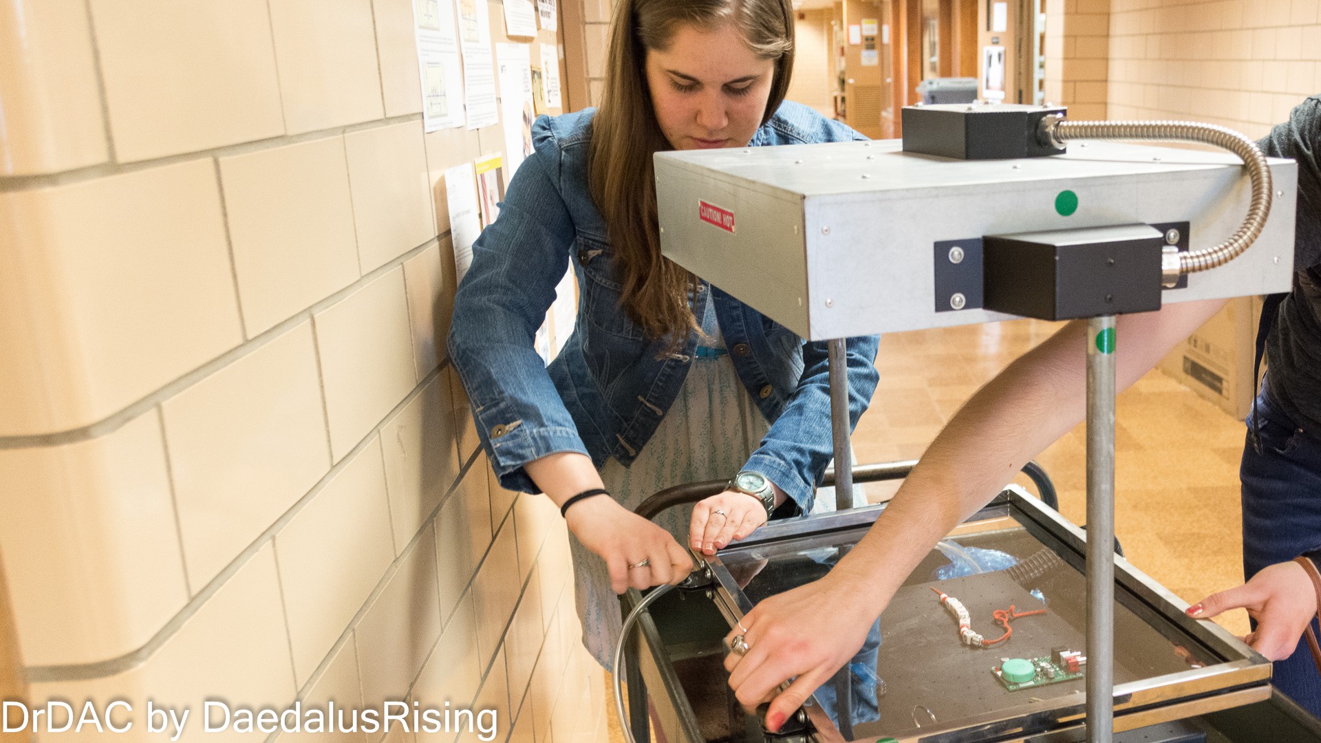
The bubble on the right was made by a contact lens cover, which served to protect the delicate soldering work of my problem IC from being destroyed in the vacuum-forming process.Learning to use the Thermoforming Machine (from the mechanical engineers):
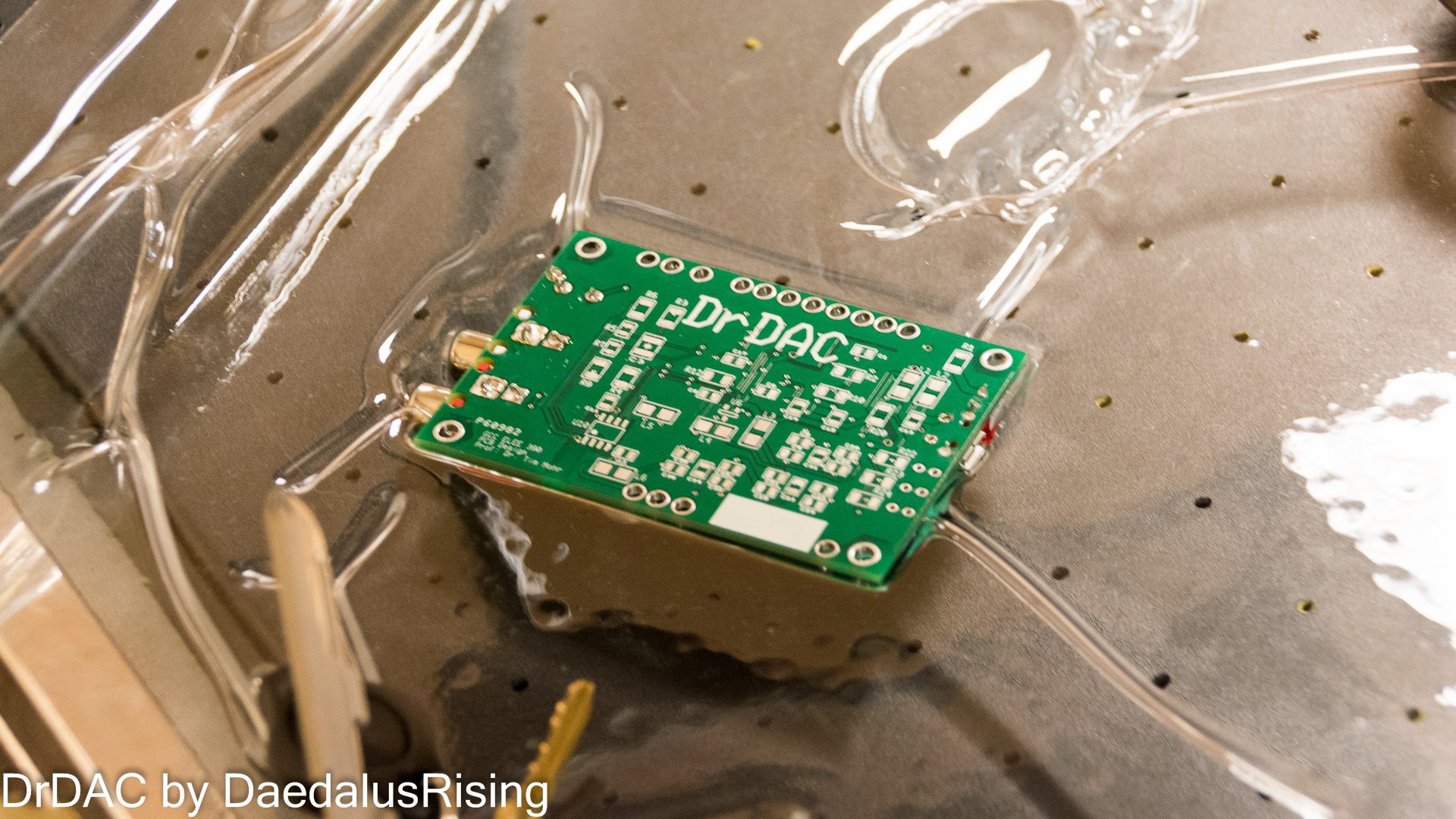
DrDAC about to be Thermoformed![]()
![]() Post-thermoformed
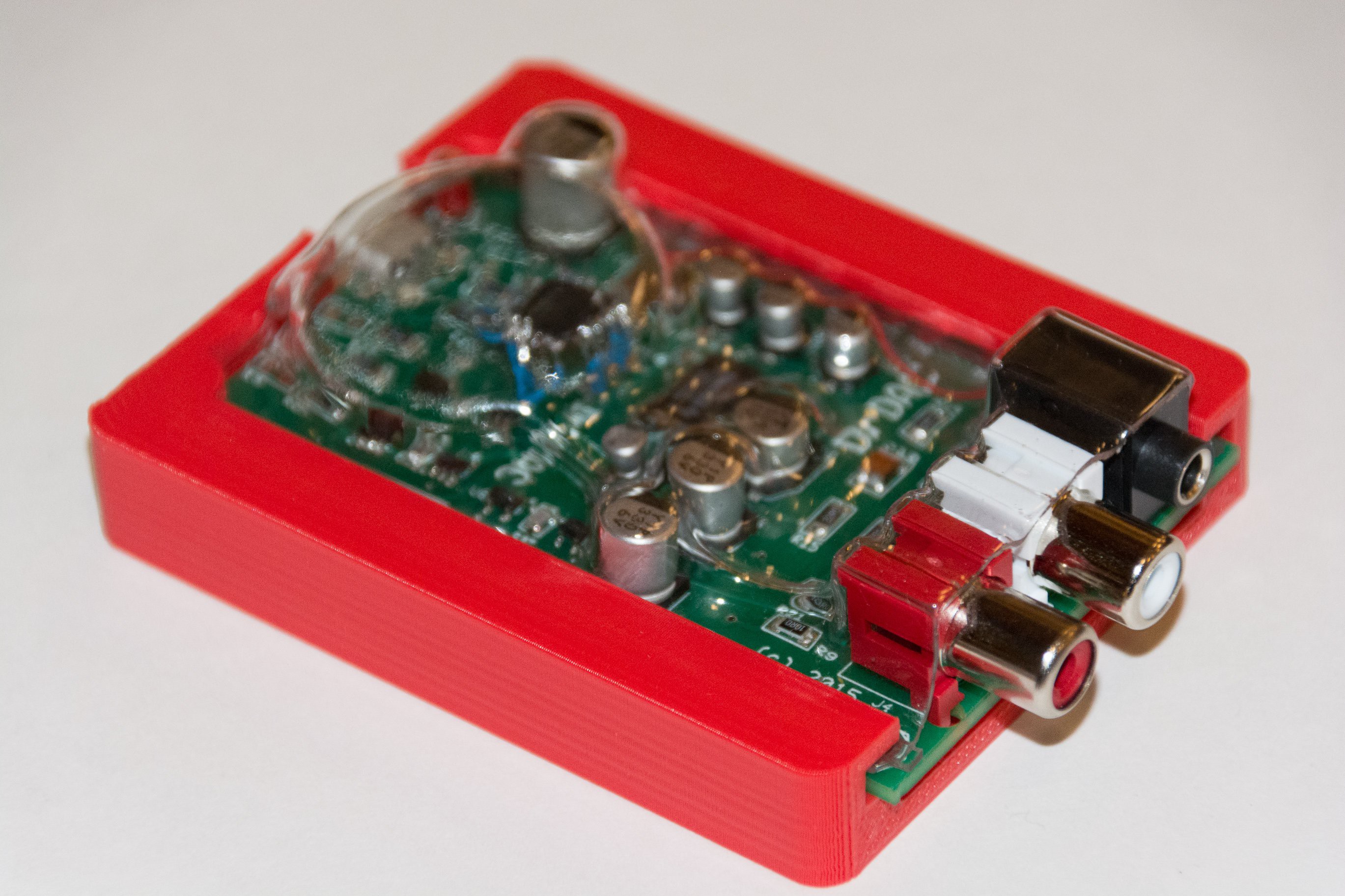
Post-thermoformed![]() With just a little bit of cutting, I had a sweet custom-fit case to protect my components!
With just a little bit of cutting, I had a sweet custom-fit case to protect my components! -
Coming Soon:
05/28/2015 at 05:08 • 0 commentsThis here is version 1.0 of my circuit board & layout. I'm hoping to add in some posts on the design of the circuit, as well as future revisions as I work towards a 2.0 version that addresses the many problems I had with this board (such as it not outputting audio, which is only a minor problem ;)
 drewrisinger
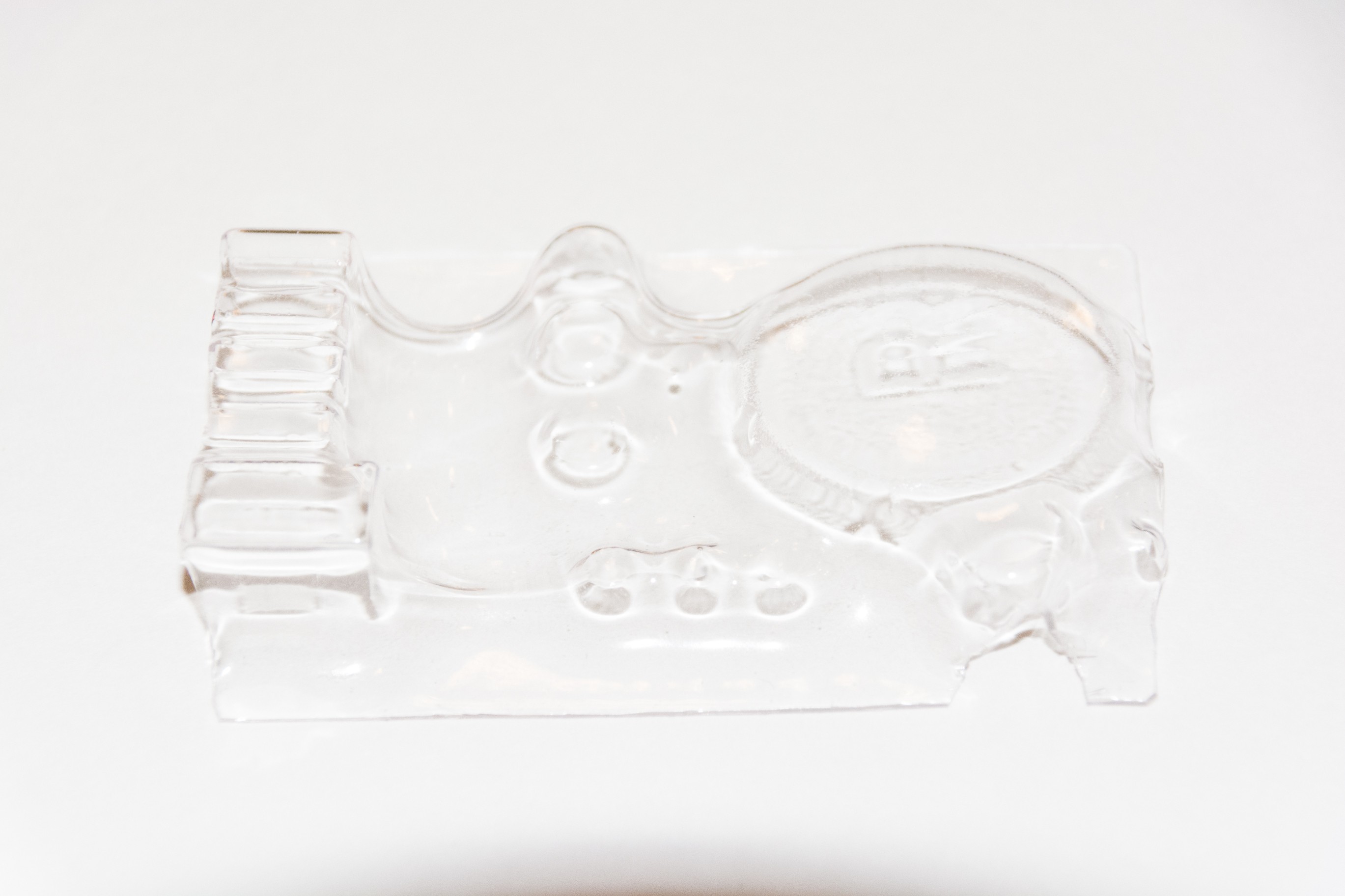 The bubble on the right was made by a contact lens cover, which served to protect the delicate soldering work of my problem IC from being destroyed in the vacuum-forming process.
 Post-thermoformed
 With just a little bit of cutting, I had a sweet custom-fit case to protect my components!