deʃhipu
-
Weight Lifting
09/04/2015 at 12:57 • 0 commentsI've been recently asked how much weight can Tote carry. So far I had to give a honest answer, that I don't know. The heaviest I had it carry was a pack of 4 AA batteries. So I decided to make a few tests.
Note, that this is a version of Tote that uses four SG92R servos for its knees, and eight SG90 servos for all the other joints. The SG92R servos are a little more expensive than SG90, but considerably stronger. Otherwise, they have exactly the same shape, so can be a drop-in replacement. Oh, and the plastic horns they come with are black, which makes the robot look much cooler!
![]()
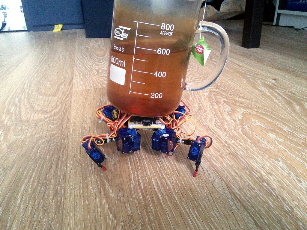
This is Tote under load of about 800g. As you can see, there is 600ml of tea, plus the beaker and teabag, which themselves weight around 200g. With this load the robot shows visible effort and the battery alarm will occasionally go off (but the robot doesn't shut down, it has to have low battery for longer time to shut down), but it holds. The battery life probably isn't too great, and I wouldn't bet on it getting through rough terrain with that load, but still quite impressive.
Another question is, considering that Tote's gait is statically stable, can it just stop at any moment and wait for its batteries to recharge? Will the servos collapse under the weight if they are un-powered? Let's try and see!
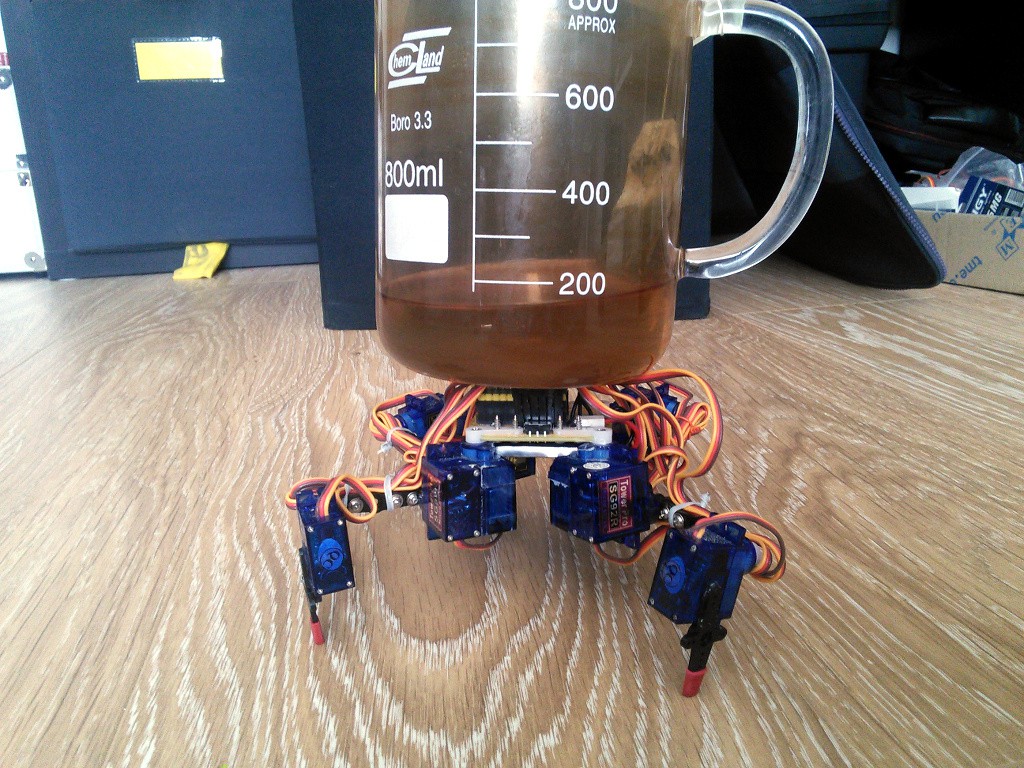
This is the robot powered off, all legs on the ground. As you can see, it's about 400g of load, and it stands. So yes, it would probably be possible to have it make several steps, then stop to recharge the batteries, then continue.![]()
-
Making Tote without a PCB
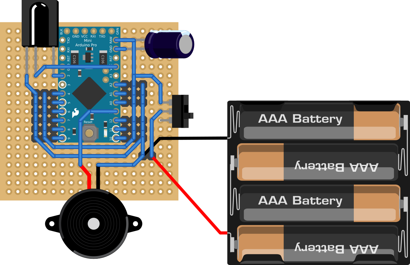
09/03/2015 at 16:42 • 0 commentsSeeing how most of robots based on or inspired by Tote don't actually use the original printed circuit board, I conclude that ordering one is the main pain point. I don't really see why, because it's not very expensive and the waiting time is about the same as with ordering the servos and all the other parts. And it's not like you won't find a use for the other 9 boards, as they are pretty much generic servo breakout boards. They are just shaped in a way that makes it easy to attach the legs. Anyways, I decided to explain how you can build Tote with just a proto-board, like #Tote in the Wild and #Micropython Quadruped Robot. Let's start with the connections (note that the connections for your IR sensor may be different):
![]()
As you can see, it's not overly complicated. The board needs to be 19x19 holes to keep the original dimensions of Tote -- if you change that, you will need to change the BASE variable in the code, so that the robot knows how big it is. If you don't like to make so many connections with wires, you can also use a strip board and cut some of the strips.
Note one trick though. The pin 13 of the Pro Mini is not used for a servo -- there is a gap in there. That's because it has a LED on it, and we want to be able to use it for signaling.
I also skipped the battery voltage monitoring circuit, so you will have to comment that section in the code, or your robot will keep on shutting down randomly for no reason.
Next comes the mechanical part. You need to drill (or otherwise make) the holes for mounting the servos. You can use an electric drill, a dremel (like me), or even simply a metal file. I made a handy template that you can print out and glue to your board to get the holes right, but it's really quite simple. Four 7mm holes in the corners, and eight small holes for the screws:
And that's pretty much it. Solder all the headers and parts, make the connections, check with a multi-meter for short circuits, and you are ready to go.![]()
You can also easily adapt for other microcontroller boards than the Pro Mini, of course.
-
Totes in the Wild
08/28/2015 at 17:27 • 4 commentsThe main goal of all this work I'm doing on Tote is to make people build their own robots. The idea is that they can start with Tote (or the elements of Tote that they like), and grow from there. Unfortunately, so far nobody that I know of decided to try it. Until recently.
I got e-mails from at least two people who are now working on their robots more or less based on Tote.
The first one is #Micropython Quadruped Robot built by @wagner. He used a permaboard instead of a PCB for the body, and translated the walking code from C++ into Micropython, to use with his pyBoard. Last time I heard from him he still had some problems with the code, but I hope he will get them resolved.
The second robot, #Tote in the Wild, made by @Over.Unity, also uses a permaboard for its body, but uses a Pro Mini just like Tote. I got permission to show you a gallery of photos of the robot. It walks around pretty well now!
I've also seen some comments under the post on Hackaday.com from people thinking about building their robots, but I've never heard from them again. If you are building a robot based on or even just inspired by Tote, please let me know! I'd love to hear about it, and see photos and videos of it.
Update: #Tote in the Wild has its project page now and is finished.
-
Out of the Prize
08/24/2015 at 23:04 • 5 commentsThis project is not one of the 100 projects that qualified to the semifinals of the Hackaday Prize 2015. And no wonder, with 900 of great projects that entered, the chances were slim. It was still great fun to participate and I won some very nice swag in the process! Keep on tracking the contest, as it will only get more interesting with time.
Of course that doesn't mean anything bad for this project. I would have worked on it exactly the same (well, maybe I wouldn't put wheels on the robot or make a dedicated controller) if there was no prize whatsoever. The real goal is to make it easier for people to get started with a walking robot and to finally get those robots into our homes.
If you like this project and its goals, there is a similar one that qualified, that you can track and support: #The Kasei Initiative. It's on a little earlier stage, but the goals are even more ambitious!
There are also other robotics projects:
- #3D Printable Robot Arm
- #Affordable, Programmable Robot Arm
- #BowlerStudio: A robotics development platform
- #Health Maintenance Robot
- #Lazy Cleaner 9000
- #MeArm - Your Robot
- #OSCAR: Omni Service Cooperative Assistant Robot
- #Project R
- #Rapidly Deployable Automation System
I will be watching them through the rest of the contest and keeping my fingers crossed for them. Good luck, and make those robots better for all of us!
-
Proprioception Revisited: Touch
08/15/2015 at 15:38 • 0 commentsSensing the positions of limbs and the forces acting on them is just part of the proprioception, there is also the sense of touch and the inner ear. Today we will do touch.
I spent a really long time looking for the right touch sensor for the robot's feet. Everything I tried was either too imprecise, too hard to trigger, too unreliable or too hard to build. I needed something off-the shelf that I could put on the end of the leg and that would tell me whether it's touching the ground or not. Seems easy.
The obvious first choice is microswitch pushbuttons, similar to that reset switch on the Pro Mini. Small, light, easy to install, simple, reliable. Except the force you have to use to make one "click" is way too large for Tote's mass. It can basically stand on them and still have them off.
Second, endstop switches. The ones with a lever. Turns out that they have pretty large travel, and that it's hard to attach them such that the lever is at the right angle. And if you remove the lever to make the travel smaller, they become too hard to trigger, like the pushbuttons.
Then came a lot of more exotic solutions. Force sensors from kitchen scales are way too expensive and too large. Bend sensors are too unreliable, and would require an opamp to actually detect the difference with Arduino's ADC. I had some limited success with a whisker in a metal tube, but that was definitely too hard to make for regular people. I even tried an optical sensor, but that only worked on flat surfaces, which kinda misses the whole point.
Finally, someone pointed me to a website of an electronics parts store where you can search the switches by the force required to switch them, and turns out there are switches that only require 0.3N! They are not pushbuttons or endstops, though. They are used for detecting whether a card is inserted into a slot. Once I knew that, I easily found and ordered those babies:
![]()
They are perfect for mounting at the tips of the robot's legs. See those plastic studs? They fit perfectly into the holes on that servo horn! And they are super-sensitive!
So add some wires, glue the switches to the legs, connect them all in series and attach to a free pin on the Arduino (since at most one leg is in the air at any given time, I only need one pin), and voila, a robot with a sense of touch:
![]()
Of course we also need software to make use of those sensors. For now I went with something really simple -- just keep lowering the leg slowly until it touches the ground. You can see the code in the "switches" branch. And the effect? See for yourself:
If you look closely you will notice, that even after the robot extends the leg far down because it didn't find the floor, it moves it back to its default position anyways -- that's why the robot's body stays at the same height even several steps, despite the imprecision of the switches. To make this actually useful, one would need to modify the gait code to keep the body at constant height relative to the average of the heights of all the legs. I will leave that as an exercise for the reader, though (or a future experiment log).
-
Hackaday Prize Quaterfinals Video
08/15/2015 at 09:14 • 2 commentsI decided to make it a bloopers video, showing the stages of development of this robot and how it reached the current form. Enjoy!
-
Version 4 of PCB Documented
08/14/2015 at 22:02 • 0 commentsAfter building two prototypes and testing them, I decided to make the version 4 of the PCB the default in the documentation. There are also updated assembly instructions with lots of photos. Don't worry, the instructions for the old boards are still there.
-
Licenses
08/14/2015 at 12:24 • 0 commentsTo be eligible for the Hackaday Prize, I have to explicitly document the licenses for everything. So here it goes.
- All the work I did myself, including the guide at http://tote.rtfd.org, the source code for the base and all the experiments, and the PCB designs, is licensed under a Creative Commons Attribution-NonCommercial 4.0 International License. See http://creativecommons.org/licenses/by-nc/4.0/ for details.
- The Arduino libraries which I depend upon are licensed under the LGPL license.
- The IRLRemote library by Nicohood, which I use for remote control, is licensed under MIT license.
- There is no other copyright-able material, that I know of, included in this project.
-
System Diagram
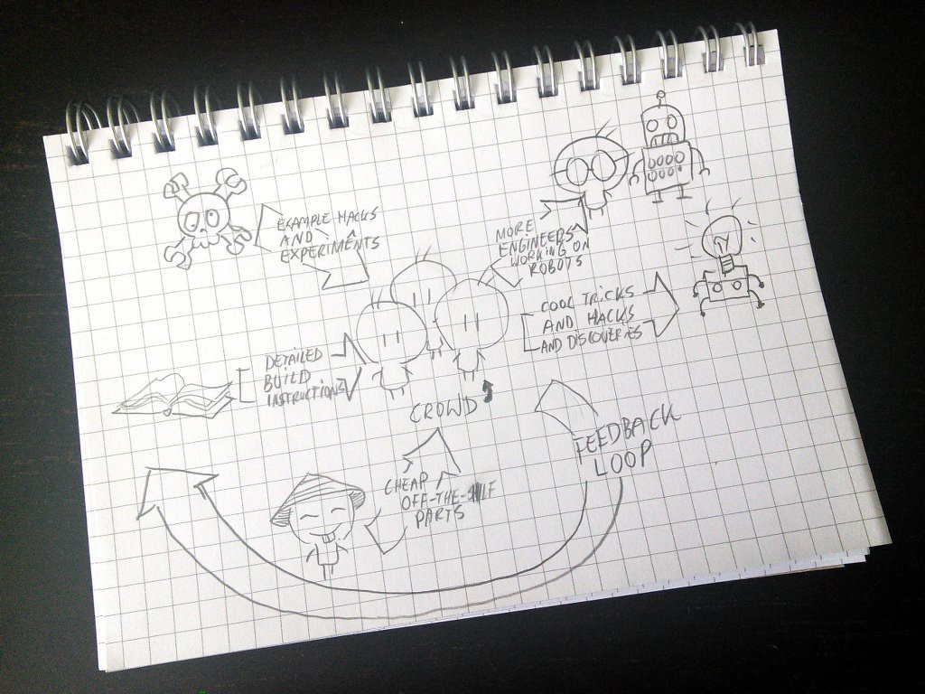
08/14/2015 at 10:55 • 0 commentsThis is the diagram of my plan to improve the worldwide robot situation:
![]()
I couldn't find a napkin, so instead I sketched it on a block of paper. Anyways, there are three "input" components. First are the detailed build instructions for the robot, that account for most of the hurdles and traps waiting for a beginner roboticist. I'm working on them at http://tote.rtfd.org and I keep improving them. Then there are the example experiments and hacks that I publish here at Hackaday.io, that are supposed to inspire and get people started. And finally we also need a source of affordable parts, that part is mostly covered by China, but on our side I need to test and document them too. The expected results are also three-fold. First, we will see an increase in people who want to work on robots professionally and make it their career choice. Second, if enough people are experimenting with this, there are bound to pop up some discoveries on how to build use those robots. Finally, part of the energy will come back and improve the project itself, making it even more effective at those goals.
-
New New Board in the Wild
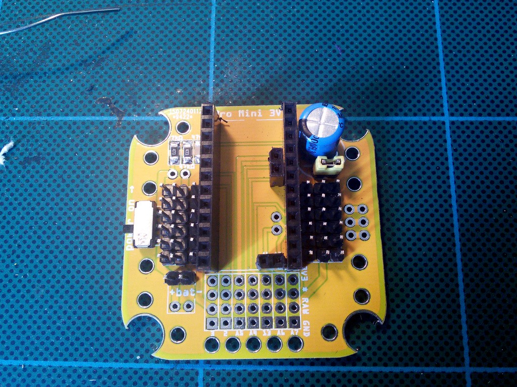
08/12/2015 at 11:02 • 0 commentsSo the version 4 printed circuit boards arrived a few days ago (no, that's not super-fast shipping from China, I just waited several weeks before even writing about them). I'm almost perfectly happy with them, so far I only came up with two small things I want to change. Probably not enough to make another version.
![]()
This time the board is bigger and the servo horns are not attached diagonally -- they fit within the board. The holes for the horns should be a little bit larger (depends on what servos you get, some of them fit perfectly) and not metalized, but that's something you can fix easily with a file. The board on the photo has all the parts soldered on one side of the board -- because I want to have the Pro Mini pluggable there. It's possible to also put the servo sockets and capacitor below, and have the top of the robot almost flat, then make use of all those mounting holes.
![]()
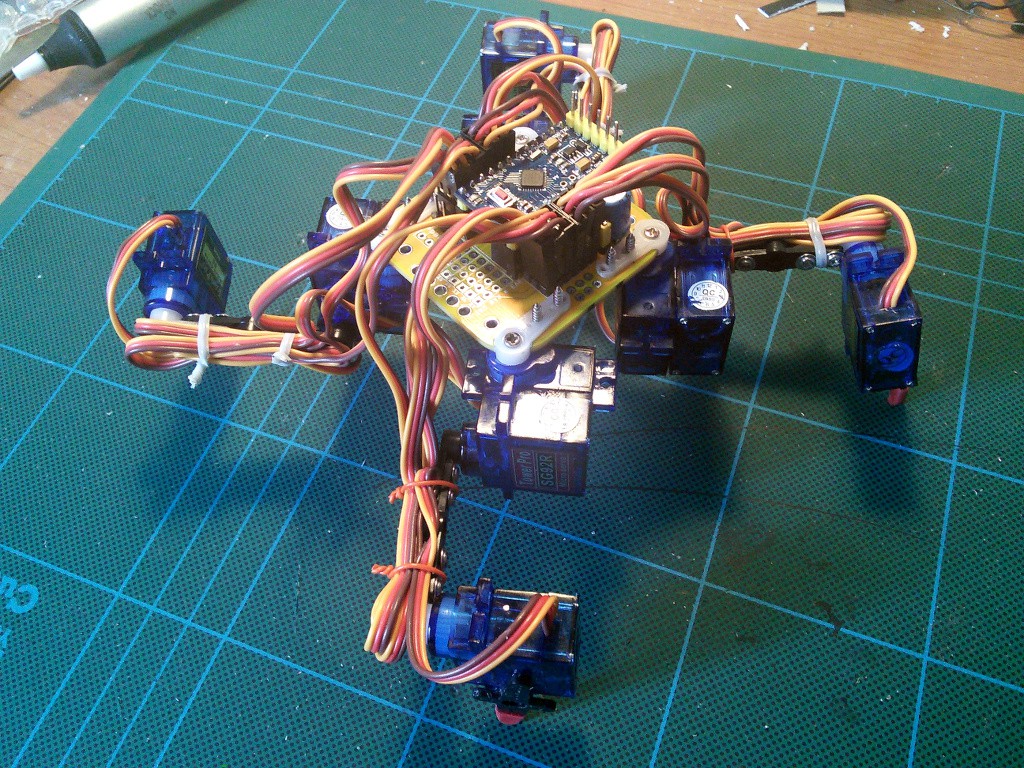
The finished robot is quite nice, and it's sturdier than the previous versions. Also much easier to assemble. I still need to fine-tune the leg positions on this one, and add the IR sensor.