 deʃhipu
-
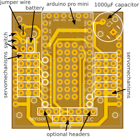
PCB Redesign
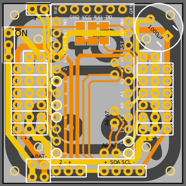
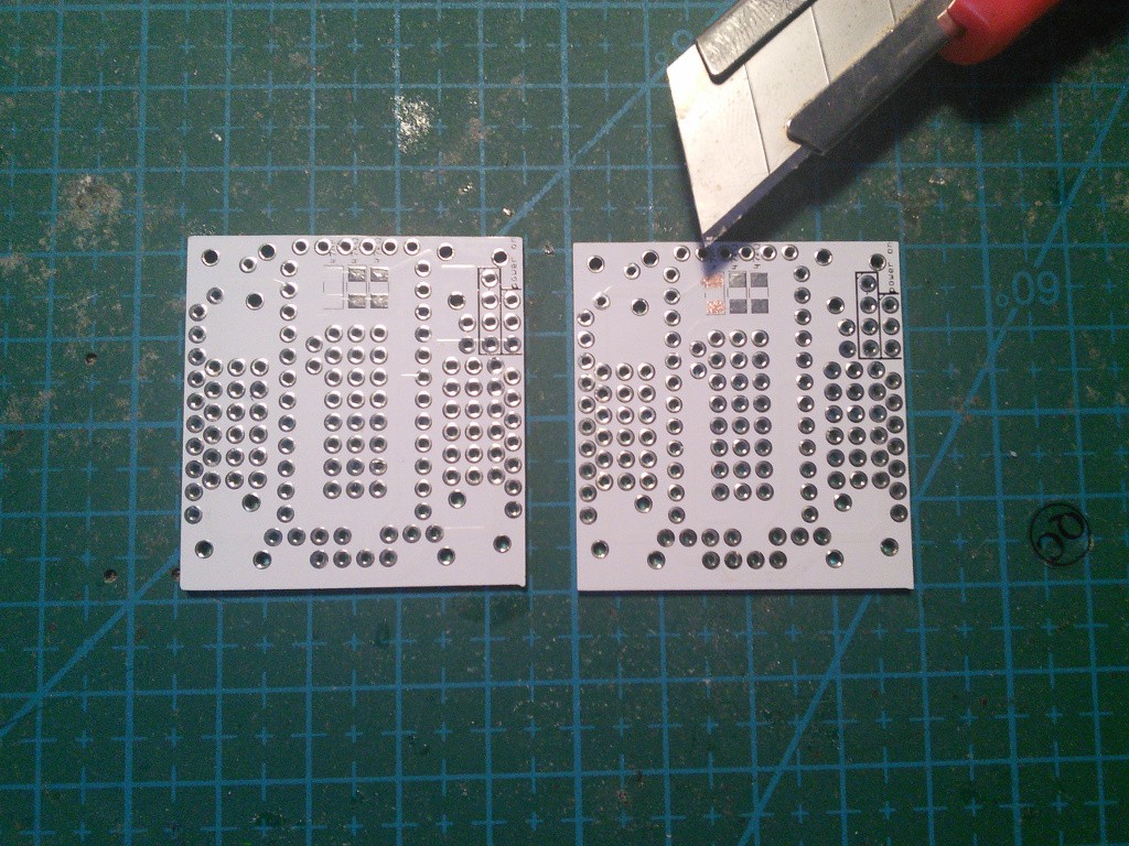
06/26/2015 at 11:39 • 0 commentsAfter the recent failures and after using the Tote's PCB in a couple of different projects, I decided that some changes are needed to the design. Here is the new PCB:
![]()
There are several changes compared to the previous one:
- a nice logo on the silkscreen,
- the board is square again,
- removed the additional holes,
- the servo connectors are moved slightly, to make more room for screws,
- battery connector moved to the front edge of the board,
- removed the HC-SR04 sensor header, since it doesn't work reliably,
- reordered the IR sensor pins to match the pinouts of my sensors,
- added a header for connecting a piezo speaker, for making noises,
- added pins for A6 and A7 gpios of the Pro Mini, for both 3.3V and 5V versions,
- you no longer need to add a jumper, that place has a connection by default, and you can cut the trace if you want to connect a voltage regulator,
- there is another trace you can cut to be able to disconnect power to the servos, but still have the Pro Mini and all the sensors powered.
Don't worry, the old board will not stop working, and I will still support it. The changes are not that big anyways -- I made sure that I don't change any pin numbers or anything similar, which would make the software incompatible.
I haven't ordered the new boards yet, so there is no link for ordering them. I will wait a couple more days for ideas for more improvements, and then order them.
-
Failure: HC-SR04 Distance Sensor
06/23/2015 at 11:00 • 0 commentsWhat is a robot without sensors? Just a remote-controlled toy! It's time to add some external sensors to Tote.
If you looked at the PCB, you probably noticed the four pins broken out at the bottom. Yes, they match the pinout of a cheap HC-SR04 ultrasonic range finder. It should be a great way to add some obstacle avoidance or person following capabilities to Tote, just like its older brother µKubik has.
So let's do it. The trigger pin is connected to pin 3 on the Arduino, and the echo is on pin 13 -- yes, I ran out of pins and had to reuse the LED pin for this. As a side effect, the LED blinks every time we read the distance. A quick sketch to test the sensor:
#define TRIG_PIN 3
#define ECHO_PIN 13


void setup() {
  Serial.begin(115200);
  pinMode(TRIG_PIN, OUTPUT);
  pinMode(ECHO_PIN, INPUT);
}


void loop() {
  unsigned long int duration, distance;

  digitalWrite(TRIG_PIN, LOW);
  delayMicroseconds(2);
  digitalWrite(TRIG_PIN, HIGH);
  delayMicroseconds(10);
  digitalWrite(TRIG_PIN, LOW);
  duration = pulseIn(ECHO_PIN, HIGH);
  distance = duration / 58.2;
  Serial.print(distance);
  Serial.println(" cm");
  delay(500);
}
And lo and behold, proper readings:Yay, so that's it, right? Now just add some basic logic to the code to make the robot stop when there is an obstacle in front, and we are ready to go, right? Wrong.
For some reason, the robot stop immediately after the first step. What's happening?
OK, let's connect the serial and see. The distance readings are all 0. Why? Disconnect the battery, connect the Pro Mini to the USB and look again. Readings are all connect. Disconnect the USB power and run it from battery -- 0 again. Argh.
Wait a minute. The Pro Mini actually has VCC at 5V while it's being powered from the USB cable, and 3.3V when it runs from the battery... What were the power requirements of that HC-SR04 sensor again? Where is the datasheet...
Right, working voltage 5V. Sigh. Of curse I did check that before when I was designing the board, but back then I still wanted to use a 5V Pro Mini, and a voltage regulator. I later switched to 3.3V and completely forgot about the sensor. So what can be done?
Well, looking at what I have lying around I took a 5V Pro Mini, a 2S LiPo battery and a 5V voltage regulator, and quickly replaced Tote's guts. Warning: the 5V Pro Mini doesn't have the RAW pin separated from the VCC pin like the 3.3V version does, so don't connect it to the USB2TTL while it's in the robot -- the power draw will quickly fry the power regulator in Pro Mini. You have to remove it for programming.
You can see that now it kinda works, except for random times when the sensor returns completely weird values. Maybe the sensor is broken? Replacing the sensor didn't help much. Taking three readings in a quick succession and taking maximum of them didn't help either -- it seems, that the sensor just has some moments when the readings are consistently bad. I can't think of a solution.
While this is a failure, I thought that I will publish it anyways, as even the failures give us something to learn from -- often even more than the successes. And speaking of failures, remember how I promised to connect a Raspberry Pi to Tote? That's too cancelled for the moment -- my A+ RPI suddenly stopped working, the power LED won't shine, the activity LED shines weakly when powered from USB, and not at all when powered through the pins. I guess I have a streak of bad luck. Oh well.
-
Remote control with ESP8266 and Micropython
06/17/2015 at 08:35 • 0 commentsSince some time I was planning to write a log about how to extend Tote with additional boards. I was planning to show examples of connecting the Raspberry Pi, Teensy 3.1, ESP8266 and anything else I could find, all running different kinds of Python. That would also let me score more points in the "mountain of prizes" as those boards use chips from all kinds of manufacturers, and I could claim then that Tote "uses" them. But reality as always interferes.
Raspberry Pi now requires at least 3GB SD card for its system image, and turns out I don't have any that big around.
The Micropython port for Teensy 3.1 doesn't yet support UART (even though the module with all the functions is there, they just do nothing).
The Micropython port for ESP8266 doesn't have enough room for my Python code for controlling the robot.
So I had to settle down to just showing how to do remote control over something else than a TV remote. I'm still using the ESP8266 with Micropython on it, except instead of controlling the motions of the whole robot with it, as I planned, I'm just passing the keypresses from the computer, and the Arduino still takes care of moving the legs. Oh well. It still took me several hours of debugging to get working.
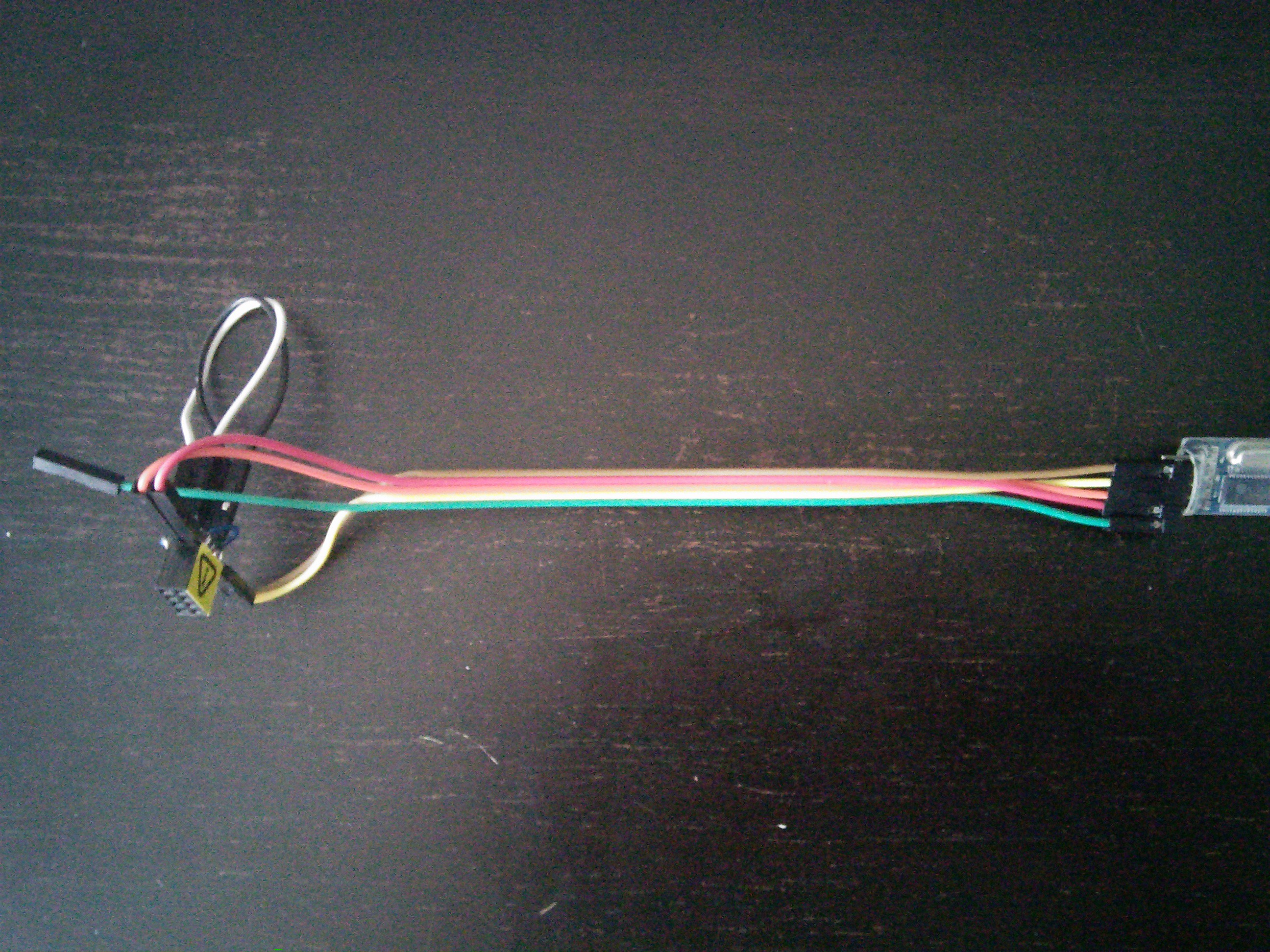
Let's start with a very simple thing -- controlling the robot over a serial cable, connected directly to an USB2TTL module stuck in your computer's USB port. You need three wires: GND, TX and RX. You connect them to the FTDI header on the Pro Mini, and to the USB2TTL in following way:
- GND ↔ GND
- RX ↔ TX
- TX ↔ RX
By the way, this is also an excellent way of debugging the robot -- you can print stuff to the serial console and verify that the program does what you think it should. Anyways, you will need some extra code on your Pro Mini too. There are two ways to go about this.
You can just have a very simple servo controller on the Arduino side, and feed it servo positions every frame from the Python code for the gaits. That's exactly what the #µKubik quadruped robot does, except instead of a serial cable it uses serial over Bluetooth. But the code is the same. This gives you a lot of control on the Python side.
The other way is to leave all the Arduino code from original Tote, but replace the TV remote part with code that simply reads the key presses from the serial. That's the route we are going to take, and it looks like this:
Now, let's replace that cable with something a little bit more modern. ESP8266 is all the rage these days, and there is a highly experimental port of Micropython for it, so why not? Those ESP-01 boards are not too useful anyways, because they have hardly any pins broken out, but they are enough for our purpose, as the RX and TX pins are there. I began by making a simple rig for programming them:
![]()
Then I followed the excellent Adafruit tutorial on flashing Micropython to ESP8266 and got a working console. Yay! Now, diving into recently added documentation, I figured out how to write a simple "repeater" server:
import esp
import sys

def recv(socket, data):
    sys.stdout.write(data)

socket = esp.socket()
socket.onconnect(lambda s: s.onrecv(recv))
socket.bind(('0.0.0.0', 2323))
socket.listen(1)
It just prints on the console anything it gets on port 2323. I saved that as esp8266/scripts/main.py and recompiled -- the ESP9266 port of Micropython doesn't yet have filesystem support, so you have to add all files to the firmware itself. Then restart, get to the console with USB2TTL, and make it connect to the WiFi:
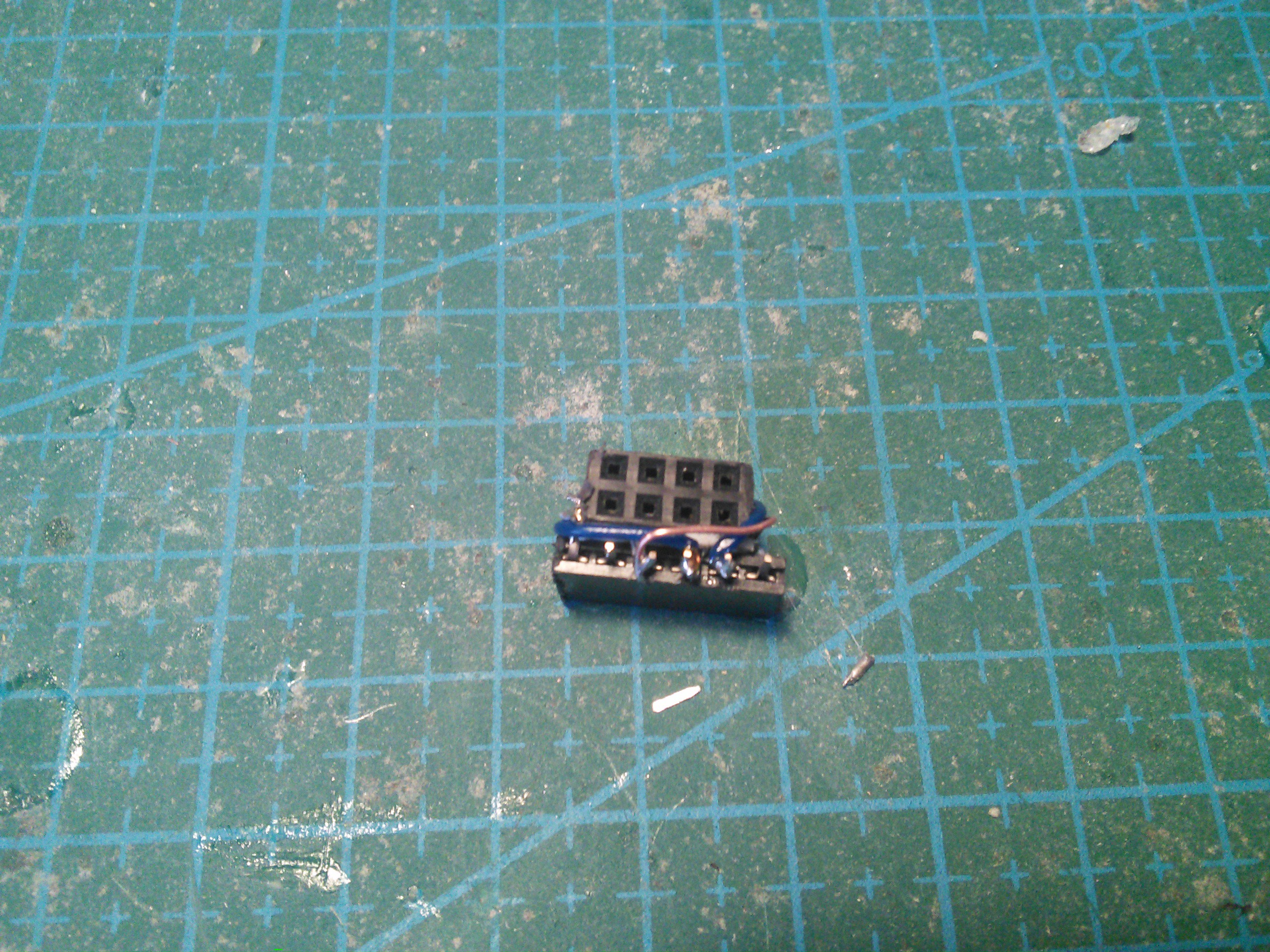
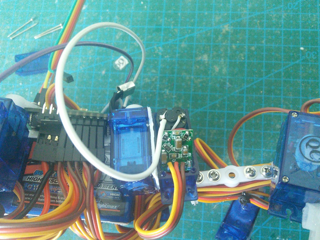
import network
network.connect('your ssid', 'your password')
That gets remembered, so you don't have to do it every time. Quick test of the server using netcat:$ nc 192.168.0.13 2323 xxx h ddddd xAnd we are finished on this side. Or so I thought. But we will get to that.Now, for the robot side, I flashed that "serial control" version of the Tote code to the Pro Mini, and made a simple connector for the ESP8266 using some female headers, two-sided tape and a bunch of wires:
![]()
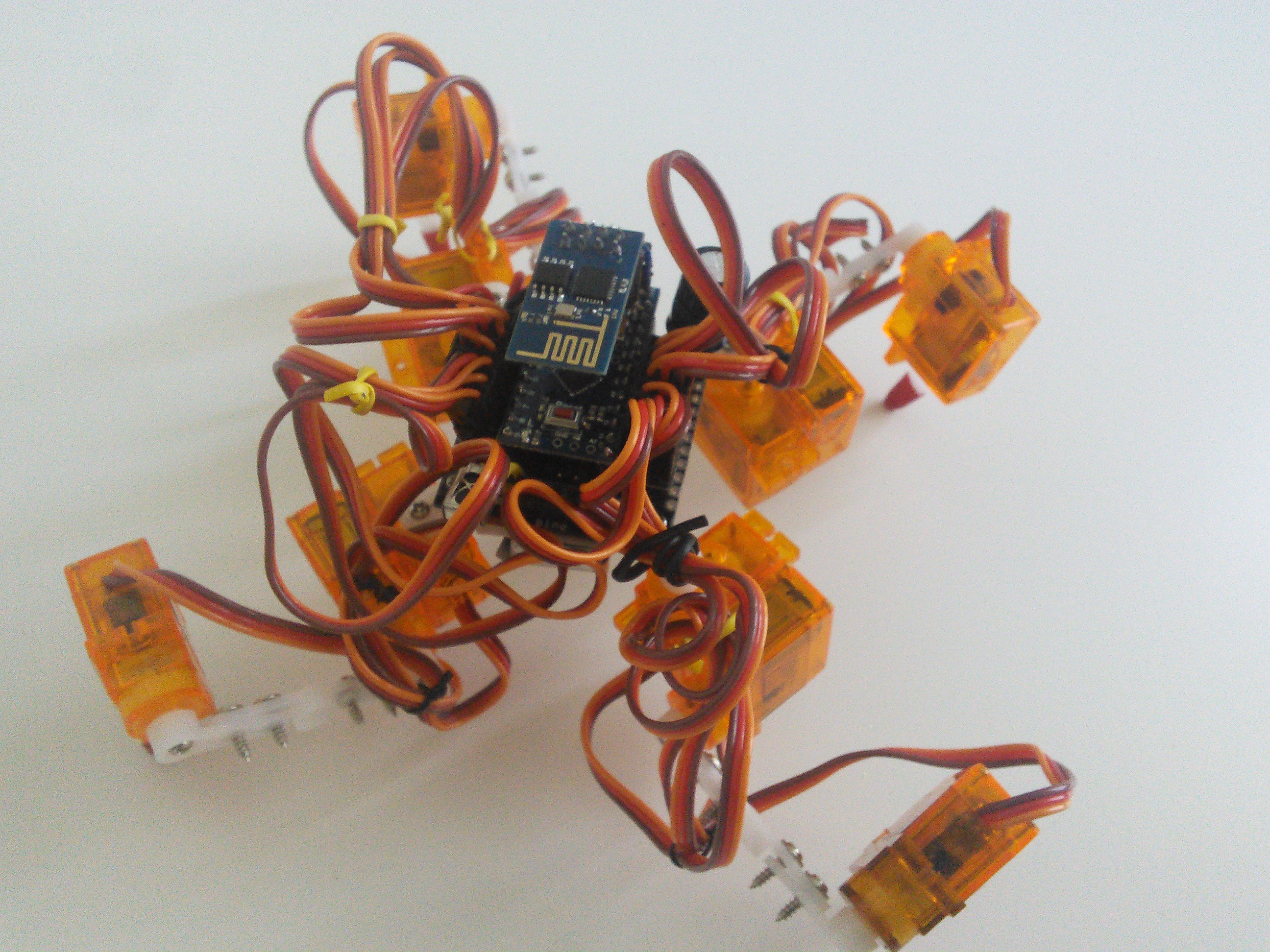
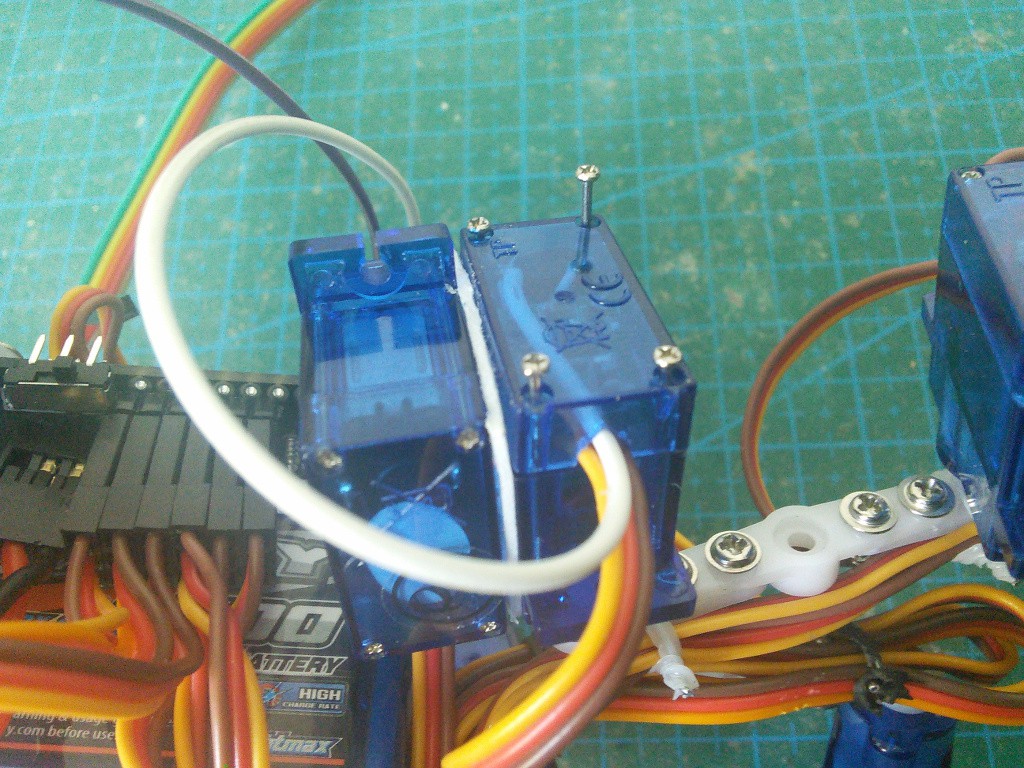
It fits nicely on the FTDI connector on top of the robot:
![]()
Now let's test it. I made it so that after powering on, the robot does nothing and waits for "xx" on the serial -- that's because many boards will print random stuff to serial while booting, and you don't want that to be interpreted as commands. So I switch the robot on, send "xx" and... nothing. What?
Fast forward four hours. I'm up to my ears in debugging. Tried 3 different ESP8266 boards and 3 different Pro Minis, debugged it using SoftwareSerial and by connecting the RX pin to the ESP and the TX one to the USB2TTL, one exceptionally helpful fellow on the #arduino IRC channel even wrote a serial-forwarding code for me in low-level AVR C. The outcome? Both the Pro Mini and ESP8266 work perfectly fine when connected to the computer through USB2TTL. But as soon as you connect them to each other and try to transmit serial data at 115200 baud rate, half the data gets corrupted. That's over a 4mm long wire. Adding pullups, pulldowns, capacitors, etc. doesn't help. I sat over this until the small hours of the night, but didn't figure out a solution. I guess I will need to start saving for an osciloscpe.
After a night's sleep, I went back to that Micropython code, grepped for "115200", and changed it to "9600", recompiled, flashed, changed the speed on the Arduino side and what do you know, it works!
Next I will try to get that SD card for the RPI and show you the more low-level control. Who knows, maybe by this time the picam also arrives, and we can have some OpenCV fun.
-
Using Arduino Pro Micro
06/10/2015 at 13:15 • 0 commentsYou can use Arduino Nano instead of the Pro Mini in Tote, if you prefer to have that USB socket available. Apart from the fact that the Nano has the USB2TTL build into it, there are no differences, so it should all work. However, I don't have a spare Nano around, so I haven't actually tested it. Caveats may appear.
Such caveats appeared when I decided to test it with a Pro Micro instead. Pro Micro is the miniaturized (both in size and price) version of Arduino Leonardo. It uses ATMega32u and has the USB support right on the chip, which makes it easy to program it as a keyboard or mouse. It also has a form factor similar to the Pro Mini, so let's see if we can use it.
First of all, never plug your Pro Micro to the USB while it's in the robot. The power lines are connected, and the servos draw so much current, that it will instantly fry the on-board regulator on the Pro Micro. That means, that you have to go with the socket version of the PCB, not solder the module directly. I am serious here, I fried one poor Pro Micro this way.
Second, the pin numbers and interrupts are different. You will need to edit servos.ino and change the whole right side of the robot, from "12, 11, 10, 14, 15, 16" to "14, 16, 10, A0, A1, A2" so that it corresponds with the pin numbers that are in those places. The LED pin, that used to be 13 on the Pro Mini is 14 on the Pro Micro, and shifted by one in its position -- we can't really do anything about it, the LED will shine all the time due to the servo PWM signal that it gets.
The pin interrupts are different too, so you will need to edit ir.ino. However, changing the interrupt number from 0 to 1 didn't seem to make the IR sensor work again, so there might be some more magic involved, or there is a bug in the IRLremote library that I'm using.
![]()
-
Dirty PCBs are dirty
06/09/2015 at 09:27 • 0 commentsFor everyone who have ordered the PCB for Tote from Dirty PCBs just a quick note. Remember, that it's the cut-throat cheap prototyping boards, and mistakes do happen. They are often simple to work around, but do test your boards for shorts before soldering anything or, especially, connecting a battery to the soldered board. I just had another batch arrive, and there is a small mistake on them:
![]()
The pads for the optional SMD capacitor are covered in soldermask, so you have to scratch them out before soldering the capacitor, if you want to have battery voltage monitoring, that is.
-
Proprioception on the Cheap
06/04/2015 at 09:25 • 11 commentsRemember that time when you sat on your leg for some time, and it got numb, and when you got up, it felt all wooden and walking was like walking on stilts? That's how most walking robots feel. What happened is your nerves got squished and blocked a little, and you lost your sense of proprioception -- the position and forces of your limbs. Now you know why robots that don't have force and position sensors on them have such a hard time walking!
What if we could add this sense to our robot? It would still be blind and deaf, but at least it would have a sense of self. It could feel its way around, knowing if a leg is standing on the floor or floating in the air, knowing if there is something blocking its movement. If we got smart with programming, we could even make it "obedient" and go in the direction you push it, just like this robot:
OK, well, maybe not as well. After all, we have limited budget and time. Plus programming the algorithm that calculates the overall force from the feedback from all the joint could be a challenge...
But at the minimum we could make our robot stop when it arrives at the edge of the table and tries to put one of its legs in the abyss beyond it. Or when we pick it up.
So how do we do it? We could attach additional sensors to the legs -- encoders for the position and pressure sensors for touch and force. I checked the parts -- they are either expensive or problematic to mount on such a robot. But wait, doesn't the hobby servo already know its position? Why not use that?
The first approach was to use an additional wire added to the servo's potentiometer to read its position. I used this excellent guide on modifying the servo. It worked. Kinda. But not as well as I hoped. The problem is that to deduce what force is applied on the leg, I need to calculate the difference between the desired position of the servo and the actual position. This difference is going to be small, because the servo's electronics are working hard to correct it. Turns out that they are smaller than the noise, even if I add filtering capacitors and software filters. Oh well.
Then I realized that the servo's electronics is actually already calculating the force, for its own purposes. Can I somehow plug into that? What if instead of reading the pot's position, I would simply read the voltage that the servo is applying to its motor? Turns out that this works quite well, at least with the SG90 servos that I have. Here's an experiment that I performed to test a "compliant motion" servo:
I soldered an additional wire to the servo's motor, like this:
I also had to make the hole in the cover a little bit larger, to fit the extra wire:![]()
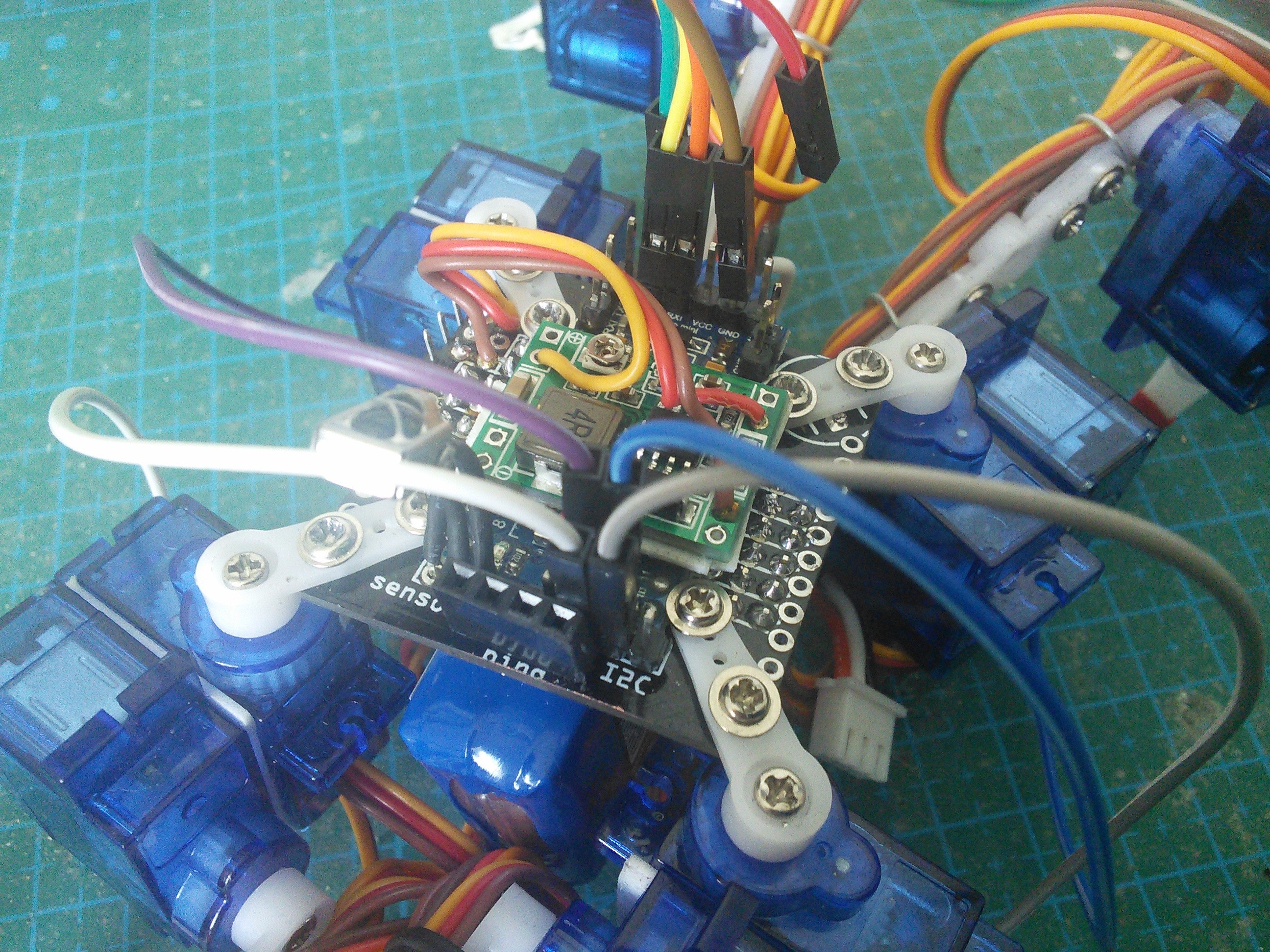
Now, just connect the extra wire to one of the free analog pins on the Pro Mini:![]()
As you can see, the robot also uses a voltage regulator that I described in the previous log. That's because I need the voltage readings from the motors to be consistent, and not depend on how much juice is left in the battery.![]()
Now just a simple addition to the walking algorithm. Every time you put your leg down, wait for the servo to get there, and then read the force from it. If the force is too small, stop. I also made all the other legs move up slightly just before the reading, to shift the weight more to the leg that we are interested in. The result is not very pretty yet, but I'm sure I can tweak it to look better:
With some tricks, I might even be able to make it walk on uneven terrain without additional endstop switches at the ends of the legs.
Update 2015-06-10:
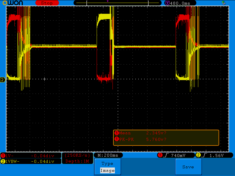
A friend of mine ran some of those servos through an oscilloscope, to see how the voltage on both of the motor wires looks like. Here's the servo going one way, stopping for a moment, and then going the other way:
![]()
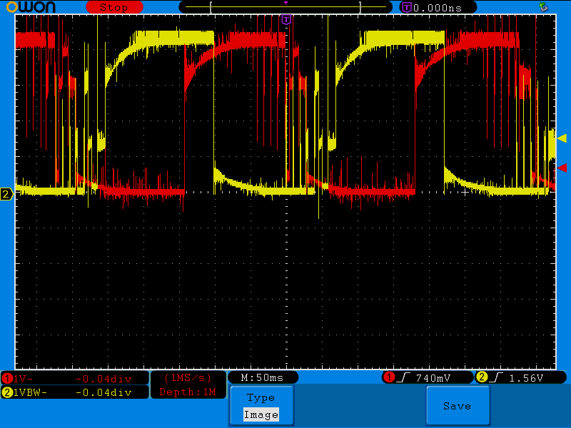
You can see that when stopped, the motor floats at about 2.3V, and goes up to 5.7V or almost to 0V when moving. You can also see that there is quite a lot of oscillating at the end, when it overshoots and corrects:
![]()
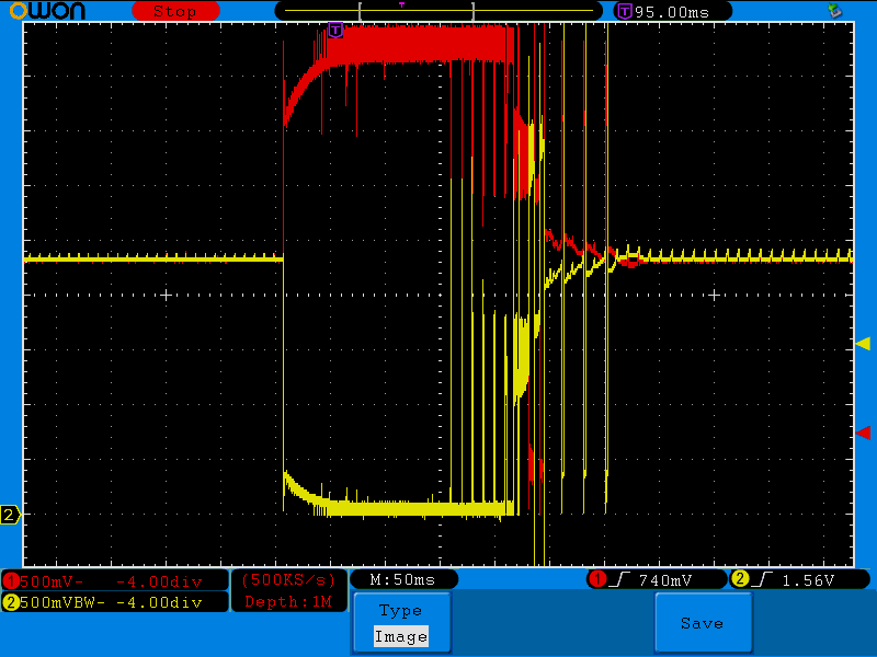
An interesting thing happens when you reverse the direction without stopping:
![]()
One of the motor leads gets high voltage long before the other gets low. Since what drives the motor is the difference, this gives the motor some time to stop and reverse, before applying the full force.
-
Different Power Sources
05/31/2015 at 14:17 • 2 commentsPower source is a hard problem for any walking or flying robots. Unlike the robots that roll on wheels (or tracks), walkers have to carry its own weight, and the battery can be easily the heaviest part of the robot. They also tend to draw quite a lot of current for their many actuators, so that further limits the choices.
For the base Tote, I went with a single-cell LiPo battery, mostly because they have the best weight-to-power ratio, and they are relatively easy to get, either from hobby model shops, from electronics shops, or from discarded cellphones, electric toothbrushes, etc. but there are other possibilities.
Alkaline batteries are well known by the robot experts as absolutely the crappiest batteries you could use for your robot. Not only they are heavy, but also the current you can draw from them is almost nothing, and they will discharge pretty quickly, after which you can simply throw them away. So can Tote be powered with alkaline batteries? Let's find out!
As you can see, you can, but not for very long. But it's nice to see that Tote can actually lift them. That means that I could probably swap them for some NiMH or NiCd rechargeable batteries, and it would be all good. Let's see!
That actually went pretty well! Apart from some weight-shifting problems, I would probably need to find a better way of attaching them. Also, using AAA cells instead of AA would improve the weight, but unfortunately I don't have any AAA rechargeable batteries on me at the moment. Finally, a LiPo battery salvaged from a broken power bank, for comparison.
That huge battery should keep it going whole day.
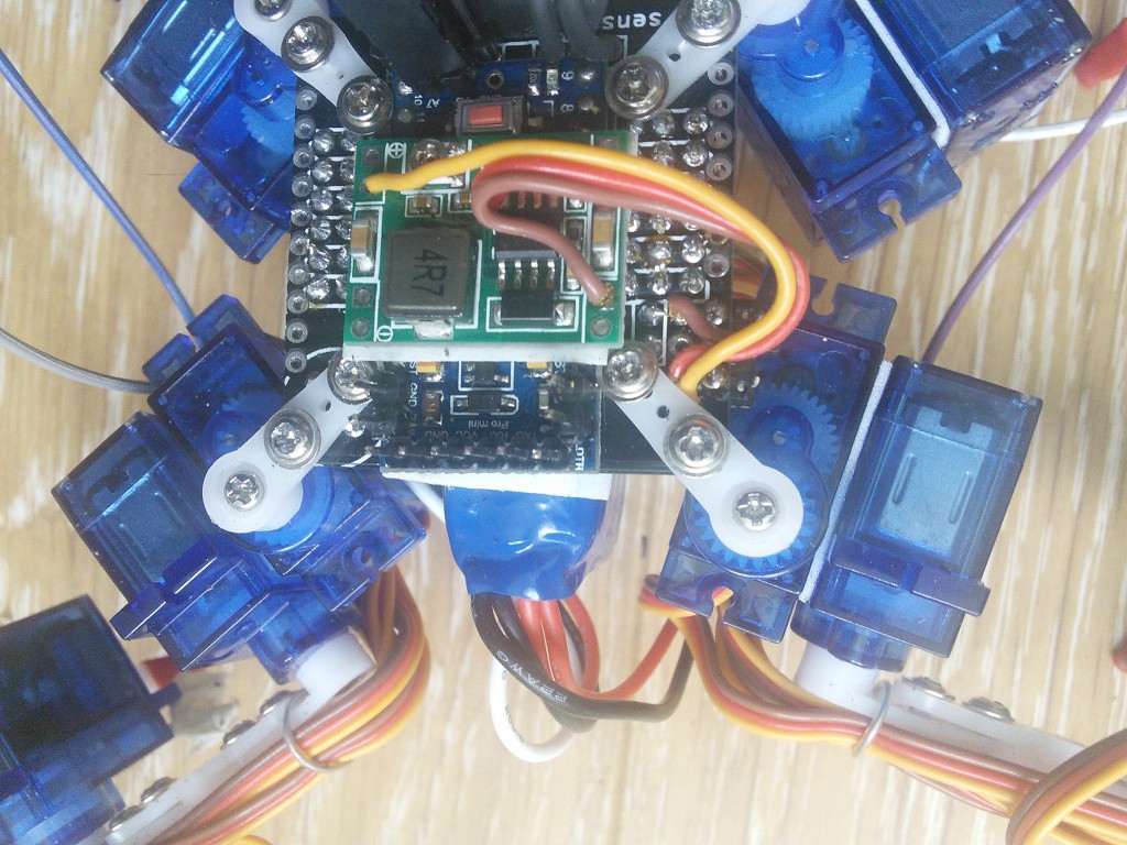
Now, let's look at some more advanced hack. For an experiment with force-sensing servos, that I will describe separately at some point, I needed the voltage given to the servos to be constant, so that I would get consistent readings. The obvious solution is to add a switching voltage regulator (an UBEC), and I actually thought about that when designing Tote's printed circuit board, so there is a place for it:
![]()
It's conveniently located just after the power switch and the voltage-monitoring circuit, so that those two will still work correctly. One problem that I had is that this regulator needs higher voltage to regulate it down to the voltage desired, so I needed to use a battery with higher voltage. So I used a 2S LiFePo4 battery here. What is that? They are all the rage these days among the power flashlight geeks. They are similar to LiPo batteries, except they are much stabler both chemically and electrically, giving pretty good 3.3V voltage and not exploding if you as much as look at them funny. Unfortunately, you need a special charger for them -- the LiPo charging modules are no good.
Of course, for experiments on your desktop, you can always just plug the robot into a bench power supply, and have it drag a cable behind. It's actually more convenient than having to recharge or swap batteries all the time. Unfortunately you can't simply power this robot from your computer's USB. It needs way more power than the 500mA the USB standard specifies.
That concludes my experiments with power sources. As you can see, you have a lot of choices.
-
Hacking on Tote
05/31/2015 at 13:16 • 0 commentsSince Tote evolved from µKubik, I put all updates about it there. But now that it is pretty much ready, I'm going to do some experimenting and extending and hacking on it, and I think it makes sense to have a separate project page for that, and leave the Python-powered µKubik alone.
