-
Hacking JACK proto to become HACK+ proto
01/14/2016 at 11:05 • 0 commentsHi there,
I went to a parts scavenging hunt through some of my old electronics gizmos that were waiting to be torn apart to find a 32.768 KHz crystal.
I found one and I'm going to solder it to PA00-PA01 pins of the ATSAMD21G mcu on JACK in order to make it more like the Arduino Zero and #HACK. In fact, the Arduino Zero core sets the main clock of the SAMD21 to the XOSC32 source. This will make JACK a HACK+ boards, to speak. We'll see what happens.
Cheers,
Mick
-
Semifinals deadline met + some videos
08/16/2015 at 22:07 • 0 commentsHey people,
I just finished uploading some videos, one of them is the Semifinals one (here):
Today I spent most of the time testing various functionalities and documenting them, some of them worked, some of them did not. Let's start with what works:
PWM and Analog inputs:
I2CSAM-BA bootloader (double tap RESET function to run bootloader mode)
I tried SPI with the Sparkfun Micro OLED module and its companion library but it gave me some compiler errors, I tried a quick-and-dirty fix for that but even after that the SPI bus seemed like plain dead, no signal on no pin (MOSI, SCLK, CS). USB is also the main pain , 'cause as seen in the videos as soon as a sketch starts the USB dies. Thanks @Atmel Corporation for implementing the double tap RESET functionality on the SAM-BA bootloader, that saved me here.
I also added the "double tap RESET" video in the details, along with a board diagram and a software diagram that briefly depict what JACK does and how it works.
Now, I'll go get some deserved sleep since the last week was quite low on sleep hours (everybody in the #Hacker Channel knows what I'm talking about!)
Cheers,
Mick
-
Protos shipped + Installation and usage guide
08/13/2015 at 09:55 • 0 commentsHey there,
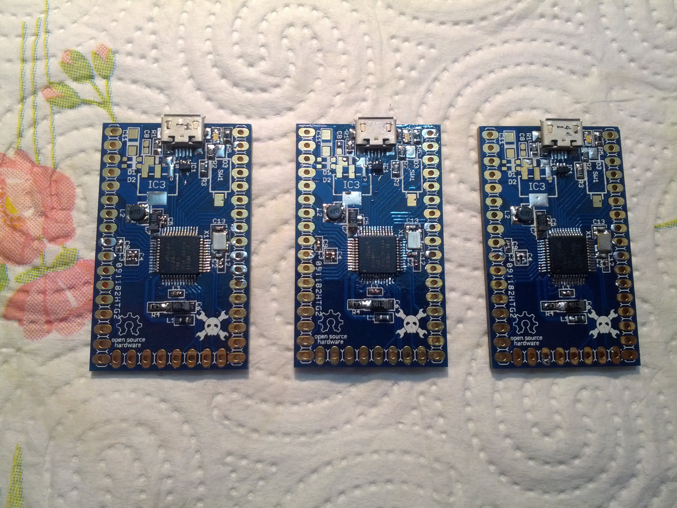
Yesterday I assembled another prototype cause two of the four I made were not working and I needed three to deliver to Supplyframe Inc..
I used a mix of hand soldering (for the TQFP package and nearby crystal/caps/ferrite bead) and reflow soldering (everything else; I placed some solder on all pads, a lot of flux, then I placed the components and reflowed them using an hot air station).
I might say that I'll use reflow soldering a lot from now on, because it was pretty easy and faster than anything I tried on these protos. I had a small issue on the LED that was not working, but I just had to add some solder on its pads and on the 68 Ohm resistor pads and it blinked correctly.
Now, for the guides, please take a look at the details of the project, which I'll update in a few minutes.
Cheers,
Mick
-
First prototypes assembled + tests
08/11/2015 at 09:41 • 0 commentsHey there,
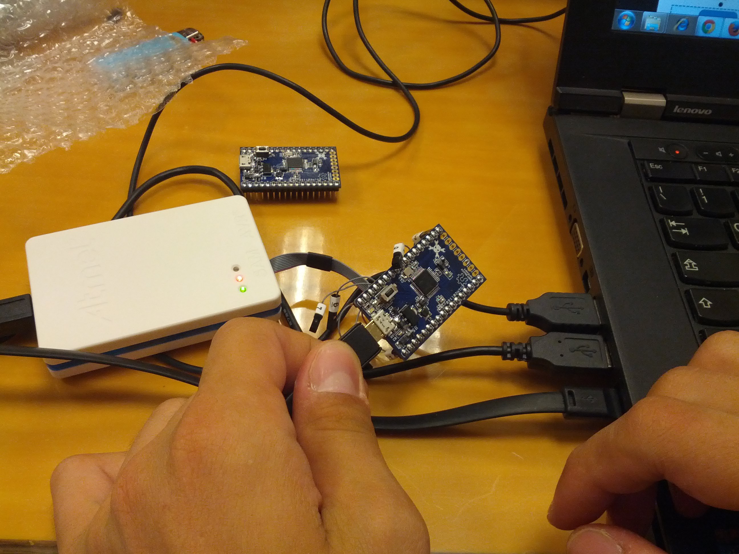
As promised, I came back from holidays last Sunday afternoon, and as soon as I got home I took my soldering iron and started assembling one proto. I had some issues cause I only had 1.2mm solder that slowed me down a lot (it took me 4 hours to get it done), but when I connected it to the Atmel ICE it was promptly recognized. Good.
Programming the bootloader worked too, but then JACK won't enumerate.
Monday morning I had to work, so I took my first proto with me along with the Atmel ICE debugger; I fiddled with the Arduino Zero bootloader first, to switch the bootloader pin to anything diffferent than PA15 which is used on my board as input for the 12.288 MHz crystal, I modded the makefile to point to correct directories, and TADA, I now have a JACK bootloader; I added a JACK board definition in the boards.txt file of the SAMD Arduino devices, opened Arduino, flashed the bootloader and and the device DID enumerate, as an "Arduino Zero bootloader" device (just like what you'd except when connecting a Zero's native USB port, not the EDBG one). I could also flash a Blink sketch, but it won't start automatically and randomly if I touched some pins it would eventually start. I thought that this issue surely is connected to the clock not being the same as the Zero.
Monday afternoon I went home early to start assembly of three others boards (the judges' boards); before that I bought a 0.5mm solder that helped me A LOT during production, it took me in fact 4 hours to make THREE boards (that's 300% faster than Sunday). I had some issues on two boards for the USB transient suppressor chip, on one I messed up 2 of 6 pins of that IC :/ In fact, these boards are still recognized by the Atmel ICE, but one of them won't show up at all as a USB device, the other would report "Unknown device". I'll try to reflow these chips using an hot air gun, if that does not work, I'll take off some parts and solder them on two spare boards
Photos here:
![]() So far so good.
So far so good.![]()
Almost there...
![]()
A pair of finished boards, one connected to the Atmel ICE.
You can also find a video of the device in action (connection to Atmel ICE, bootloader flashing, enumeration as Arduino Zero, programming of Blink sketch, LED blinking):
To solve the issue that I had yesterday I indeed had to change the Clock Generators; the Zero takes the main oscillator from an external 32.768 KHz crystal while I'm using a 12.288 MHz crystal; these crystals have separate pins. I then reconfigured the Zero startup.c file to use XOSC rather than XOSC32K as main source and you can see in the video that as soon as I program the device with the Blink sketch, it loads it.
I still have a software issue, that is when I flash JACK with a sketch it won't enumerate anymore as an "Arduino Zero bootloader" COM port so I cannot program it again. I also enabled an option that if you tap twice the RESET button the bootloader is forced to load again, but it won't show up either.
See you soon for other updates.
Cheers,
Mick
-
Going out for holidays + little mishap on cap C8
07/31/2015 at 15:17 • 0 commentsHello there,
I'm going out for holidays today and I'll come back in Italy Saturday 8th August evening; I'll spend next Saturday night and all Sunday 9th soldering and testing the prototypes to be sent in before the deadline.
I had some spare time to write a little instruction log here, and while looking for the best order to solder the components I noticed that I had a mishap on cap C8, the layout was done with package 0402 but I ordered 0603 parts... I'm sure that won't be a problem but this issue coupled with the JACK logo not being printed on silkscreen, and the fact that a few components could be moved around to improve easiness of mass production (make all passives oriented in the same way) leads me to what I need to change in revision 2.
Stay tuned for next weekend's progress!
-
PCBs delivered! But LDOs are still out in the wild...
07/30/2015 at 09:36 • 0 commentsHello there,
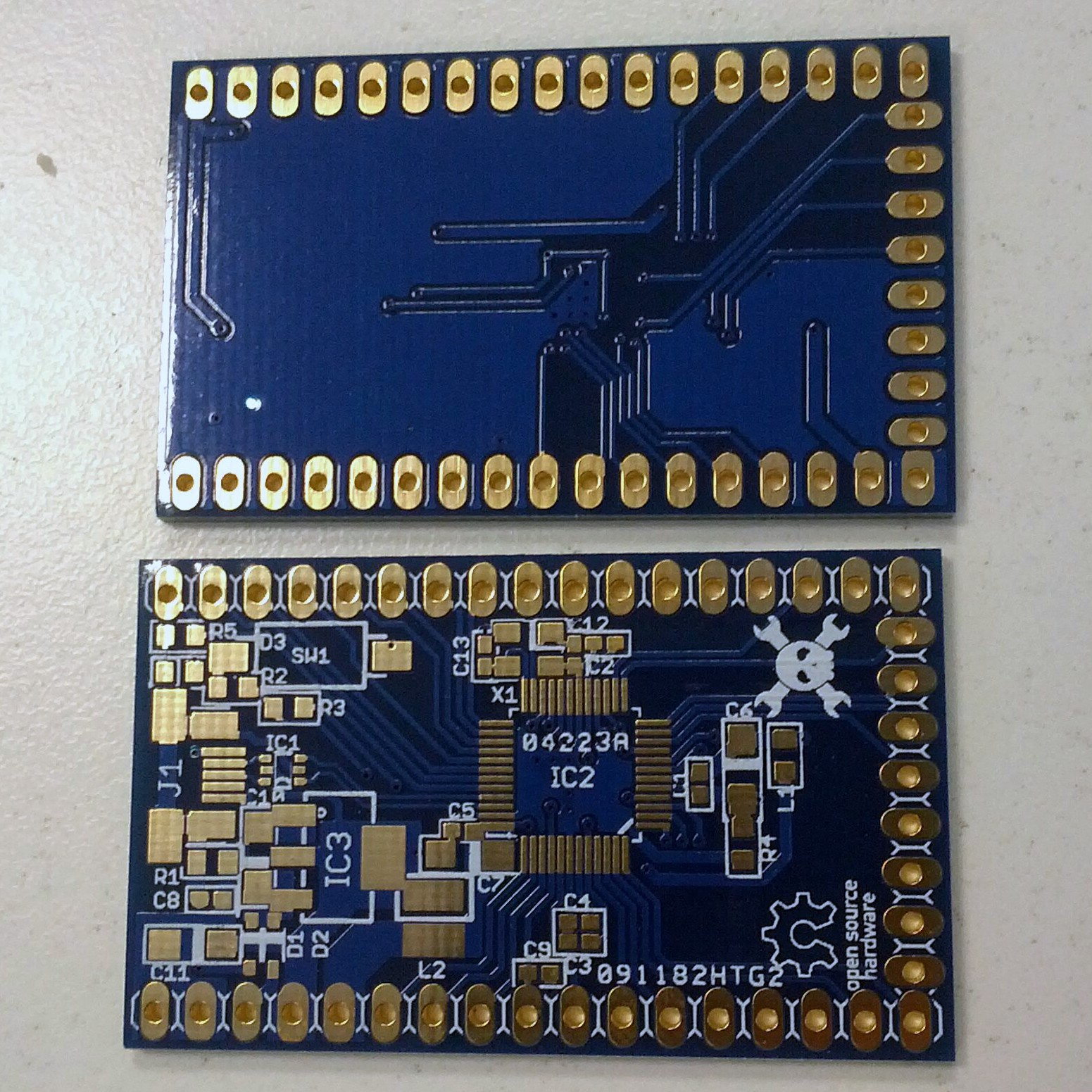
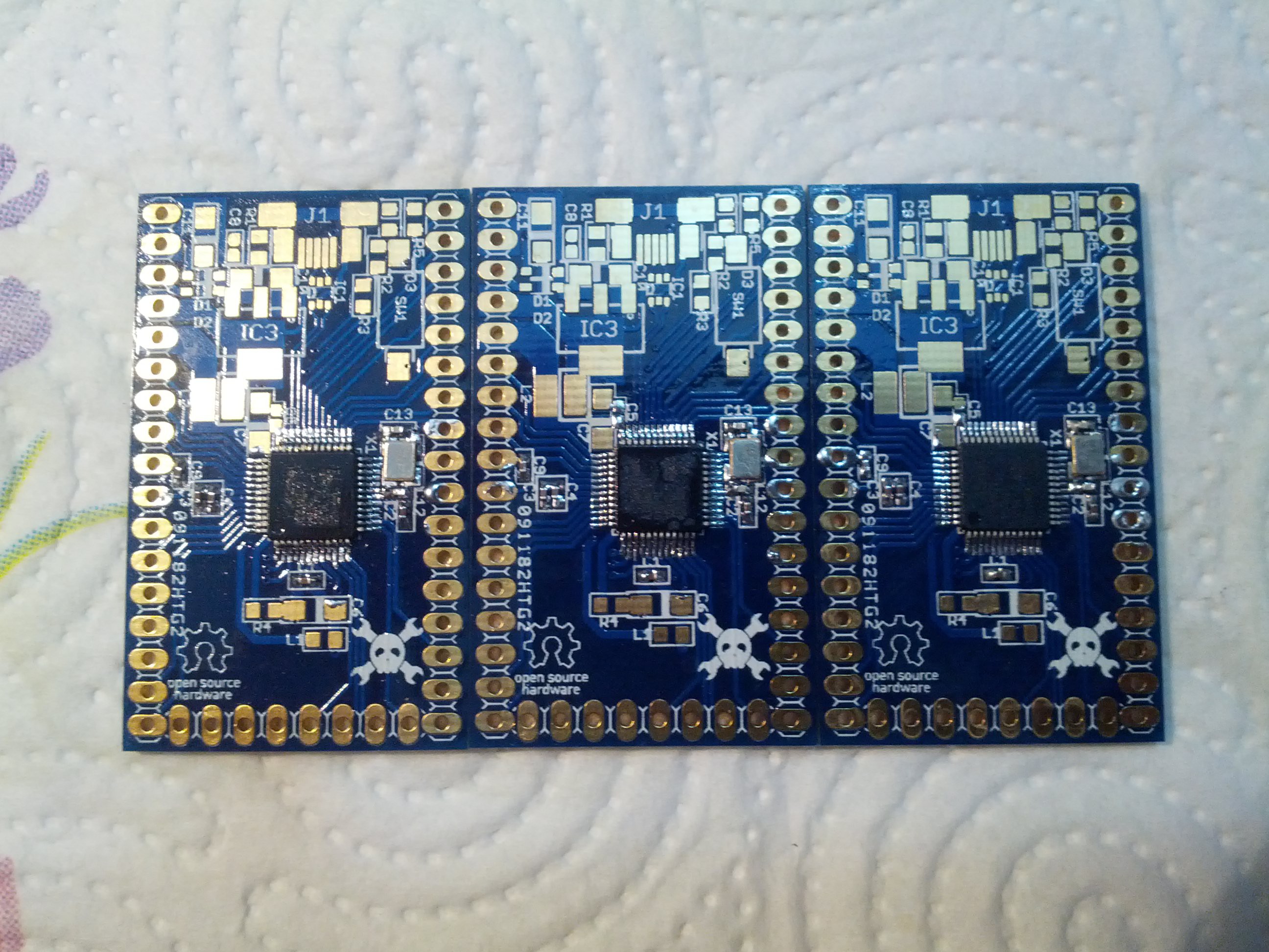
another update: the PCBs have been delivered this morning in all their Blue slik+ENIG finish beauty! Too bad the JACK logo didn't come out on the silk screen :(
Photo attached:
![]()
Lastly, my order from RS Components got split in two for no apparent reason, and I'm therefore short of 20 LDOs. Luckily I remembered to add ONE on my bulk Mouser order, but still, if I don't get these missing LDOs soon I'll be forced to wait to build my test units. Oh well, at least I can flash ONE unit for my tests.
Cheers,
Mick
-
Mouser order + TV-B-Gone shipped!
07/27/2015 at 15:48 • 0 commentsHello there,
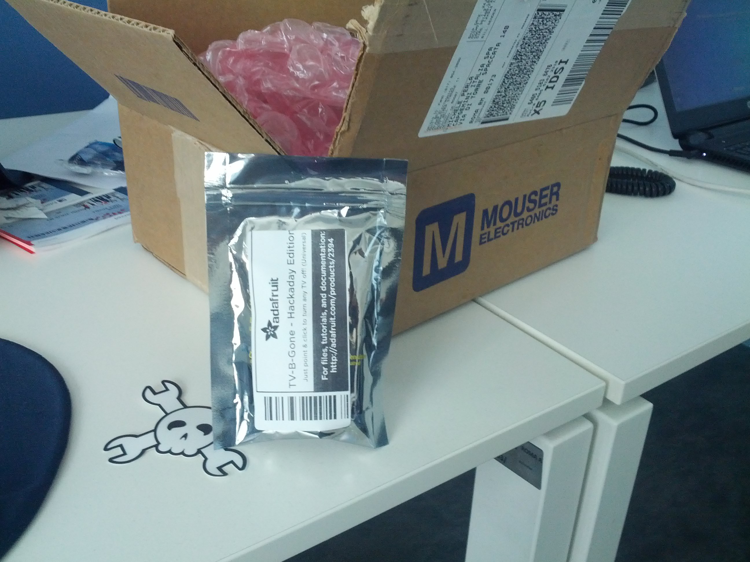
Quick update, I just received the package from Mouser! Ordered Friday at 6 PM and received at 2 PM today, that is FAST.
Little "early-christmas" photo here:
![]()
This thing is getting real...
:D
-
Parts, PCBs and ICE Debugger on their way!
07/27/2015 at 10:28 • 0 commentsHey people,
In the weekend I ordered all the stuff that I need to assembly the test units; the PCBs are coming from Smart Prototyping (http://smart-prototyping.com/), a nice electronics services company based in China, while components and ICE Debugger were ordered from @Mouser Electronics and from RS Components (I forgot to add a few spare components in the big order from Mouser, plus Mouser is not allowed to ship chemicals to Italy and I need a flux cleaner that RS can ship since they have a storage here in Italy). Of course, I went with the expedite options where possible because I'm leaving for holidays this Friday 31st to Croatia and I'll be back in Italy on Saturday 8th August. I hope I'll receive everything within this Thursday, so that I could at least have the time to assemble one board and test it ( I'll do that overnight, of course :D ) before leaving for holidays. I can't wait to see the blinky LED hello world thingy flashed on JACK :D
I'll post an update before my holidays begin.
Cheers, Mick
PS: I'm updating the components list to reflect the real-life components I chose for this project ;)
-
3D Preview (woohoo)
07/23/2015 at 18:07 • 0 commentsHi people,
before proceeding with PCB and components ordering I decided to give a try at 3D modeling of a PCB. I used eagleUp to export from EAGLE to Sketchup, I donwloaded/created some missing models and I could finally see what the board will look like when finished.
The 3D preview is really helpful too to see if there's any misalignment of the actual part or if some part intersects with others.
This project looks really promising. And the blue PCB will be sooo coooooool
Next step will be ordering PCBs from Elecrow and parts from @Mouser Electronics. I'll receive 10 PCBs but I'll populate 5 only, 3 of which are going to @Benchoff , @Mike Szczys, @Adam Fabio and all the Hackaday people to judge. I'll keep one for me, and I'll probably send one away to be reviewed by Dave Jones maybe? That'd be really cool, too.
PS: @Mouser Electronics and @Atmel Corporation, any sample of the parts listed in the Components section will be much appreciated.
PPS: every update is already on github ;)
-
Reduced board size, now well under 3x5 cm^2!
07/15/2015 at 21:29 • 0 commentsHey there, quick update:
I managed to shrink the board to fit in less than 5 cm in lenght, it now sports an 8 pin side header. This way the board can be produced using the cheapest available option from any fabhouse, that is less than 5x5 cm^2.
I'll post updated photos here tomorrow, while Github is already up-to-date.
Cheers
JACK
just another cortex kit - Cortex M0 development kit with an Atmel SAM D21, a USB device port, an LDO, some passives and breakout headers
 Michele Perla
 So far so good.