0%
0%
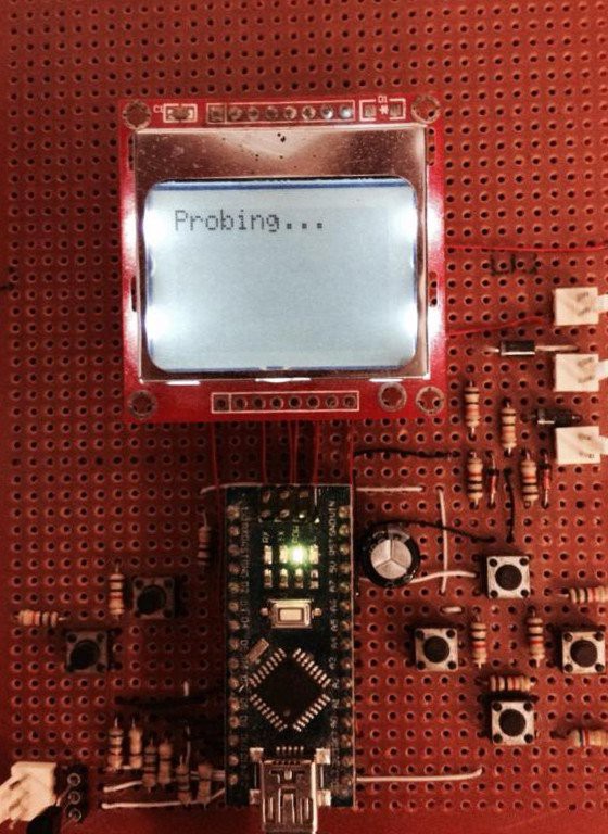
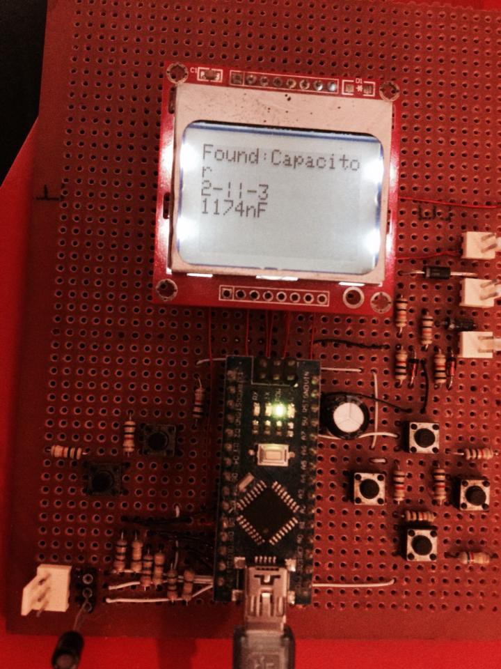
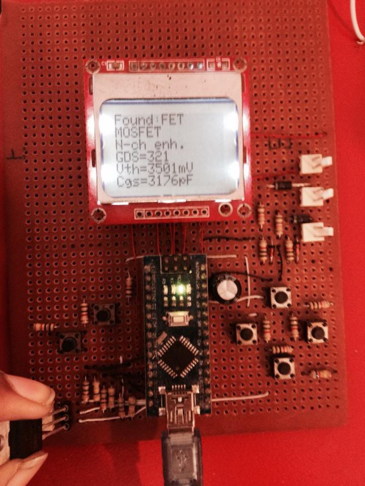
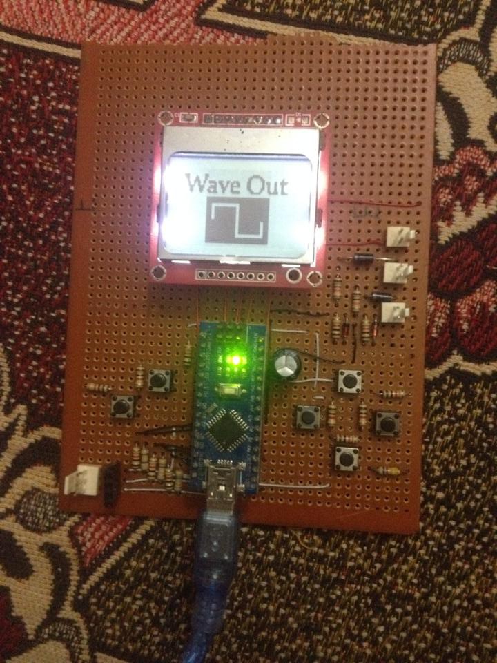
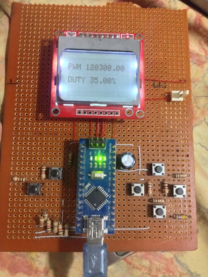
Engineers Multi Tool
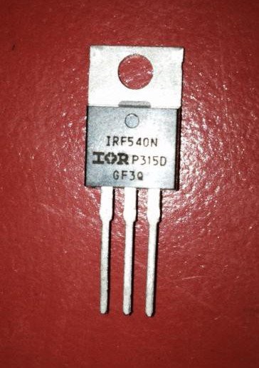
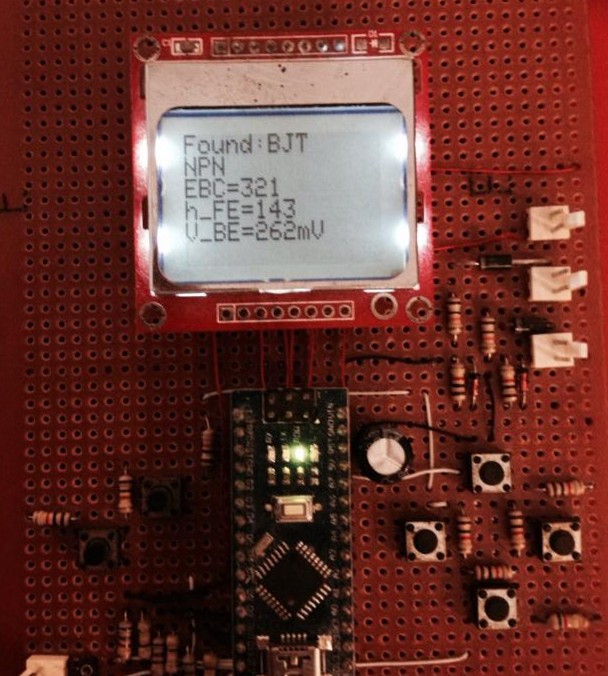
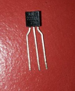
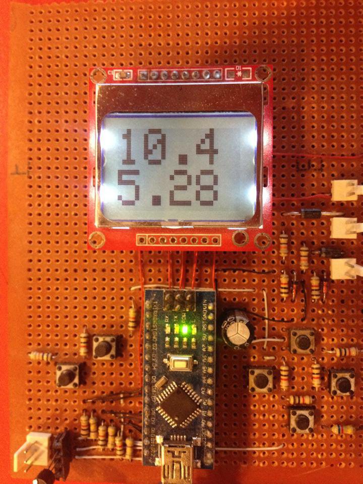
a tool for electronics engineers/students to use - planned to include basic Voltmeter, Ammeter, Component Tester, Serial Terminal etc
 ZaidPirwani
Become a Hackaday.io member
Already have an account? Log in.
Just one more thing
To make the experience fit your profile, pick a username and tell us what interests you.
Pick an awesome username
hackaday.io/
Your profile's URL: hackaday.io/username. Max 25 alphanumeric characters.
Pick a few interests
Projects that share your interests
People that share your interests


 Thatcher Chamberlin
 Andy
Andy
 mircemk
Please, I would like a copy of the schematics if possible. My e-mail is halilcetin54@gmail.com