 Kevin Uhlir
-
1Step 1This project requires DIY assembly and soldering skills. At this time there
is no pre-made board. I've made two of these systems so far, and both of them
are done with proto boards and point to point wiring and assembled in a
water resistant project box. -
2Step 2
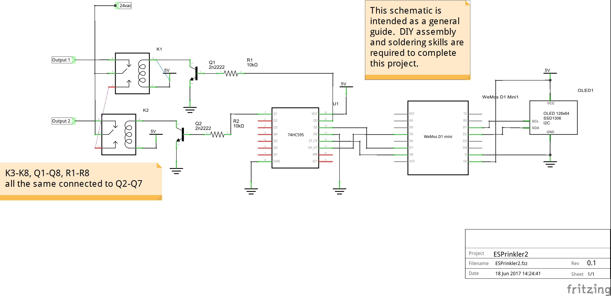
General Hardware Description
An ESP8266 with 4MB (32Mb) of flash is required. The software makes extensiveuse of the flash storage for both OTA updates and spiffs. Generally this is
an ESP-12x, but other models may be used. In my case I used a WeMos D1 Mini
as the ESP8266 board. I had some in the junk box and it has the 3.3v
regulator, and the usb to serial interface built on board. It also includes
a nodemcu type reset and programming circuit.The 8 relays are controlled through a 74HC595 8 bit shift register. This is
simply wired to the SPI interface of the ESP8266 (CS (GPIO15), CLK (GPIO14),
MOSI (GPIO13) connected to Latch, Clock and Data In of the 74HC595).The shift register outputs are then connected via resistors (10k or so) to the
8 NPN transistors acting as relay drivers. In my particular case I had some
quad transistors in a 14 pin dip package in my junk box.These transistors then drive 8 mini 5v relays. The relay contacts connect
24vac to the corresponding output, and therefore energize a sprinkler solenoid.A 24vac center tapped transformer powers it all. One leg of the transformer
output is ground for the circuit, the other side is routed to the relays to
control the solenoids. The center tap is rectified through a single diode
to feed the input of a buck type dc-dc switch mode converter. The output
of the convert is set to 5v and is routed to the relays and to the D1 Mini.The ST1306 OLED is an I2C device and therefore connected to SCL (GPIO5)
and SDA (GPIO4) of the ESP8266.For the optional real time clock (pcf8563 or ds1307), I rigged that up on a
proto board stacked on the D1 Mini using stacking pins.The following schematic can be used as a guide. A Fritzing file is also
included. It is also just a guide. Again DIY assembly and soldering skills
are required to complete this project.![]()
-
3Step 3
Gather the Software
- Arduino-1.8.3
- ESP8266/Arduino :Additional Boards Manager URL:
http://arduino.esp8266.com/stable/package\_esp8266com\_index.json
- Time 1.5.0 https://github.com/PaulStoffregen/Time
- SimpleTimer https://github.com/jfturcot/SimpleTimer
(http://playground.arduino.cc/Code/SimpleTimer)
- NtpClientLib 2.0.5 https://github.com/gmag11/NtpClient
- ArduinoJson 5.6.7 https://github.com/bblanchon/ArduinoJson
(https://bblanchon.github.io/ArduinoJson/)
- U8G2Lib 2.13.5 https://github.com/olikraus/u8g2
- orbitalair-arduino-rtc-pcf8563
https://bitbucket.org/orbitalair/arduino\_rtc\_pcf8563/downloads/
(https://playground.arduino.cc/Main/RTC-PCF8563) -
4Step 4
Don't forget to restart the Arduino IDE after installing the libraries
and boards (See the list previously under Software).Set your esp settings.. the board, programing method, flash size 4M3M.
This uses the SPIFFS file system. So we need to load that in your
esp-12x first. For quicker loading of web pages, almost all the files on
the spiffs flash are gzip compressed and they have the suffix ".gz".
The uncompressed data version of all the files is the "Master" in the
"data-uncompressed" folder. The compress-data.cmd file (windows) will
compress the data in preparation for uploading. If you've not made any
changes to the contents of data-uncompressed, you don't need to do this step.Upload the contents of the data folder with MkSPIFFS Tool
("ESP8266 Sketch Data Upload" in Tools menu in Arduino IDE)Then compile and upload the .ino.
-
5Step 5
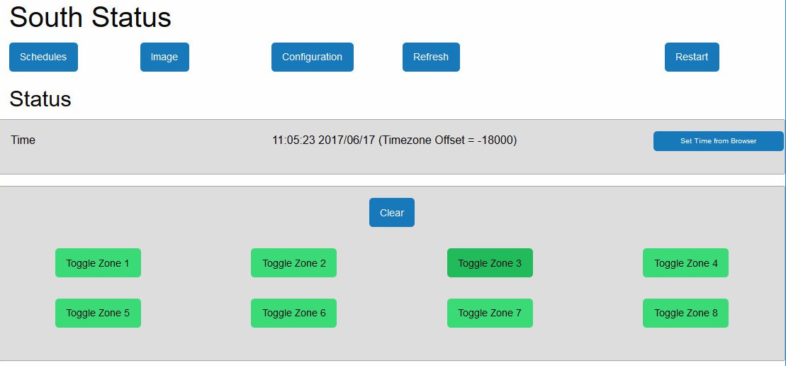
When initially powered on, the internet access point will not be setup.
The ESPrinkler will therefore switch to AP mode. It will be come an
access point in itself.So connect to ESPrinkler2_XXXXXX with a wifi enabled device (no
password).Browse to 192.168.4.1
The initial page will let you toggle the relays on/off to test.
But the first thing you'll want to do is click "Set Time from Browser". Both
the time and the correct time zone are now set up.Now go to the Configuration page
Set a host name. This will help allow you to access the device from your
browser (if you can use mDNS).Set your access point name and password. You have 2 choices here.
- If you want to connect the device to your network, fill in your access
point SSID and password.
- If you want to leave it as a stand alone access point all by itself,
fill in the second set of SSID and Password, to secure the access point.Click Save Configuration, then click Restart.
What is it's IP? If your computer supports mDNS (Anything but windows,
but even on windows it'll be there if you have loaded iTunes), you can
access it with the following url: http://.local/, where
<host> is the host you specified in your configuration. If you don't
have mDNS available, you must find the IP address of the ESPrinkler2
through one of the following methods (or make up your own method)- Look at the OLED display (if you're using one)
- Log into your router and look at the dhcp leases (sometimes called
dhcp client list) find the entry that shows ESP_xxxxxx
- Connect a serial ttl dongle to the ESPrinkler2, set the baud rate to
74880. During startup, you'll see the IP address shown.
- Get mDNS on your computer: here's some info for windows:
http://stackoverflow.com/questions/23624525/standard-mdns-service-on-windows
- ping from a computer that does handle mDNS -- ping <hostname>.local![]()
![]()
WiFi Lawn/Garden Sprinkler Controller (ESP8266)
An eight zone Wifi accessible, sprinkler valve controller based on an esp8266.

Discussions
Become a Hackaday.io Member
Create an account to leave a comment. Already have an account? Log In.