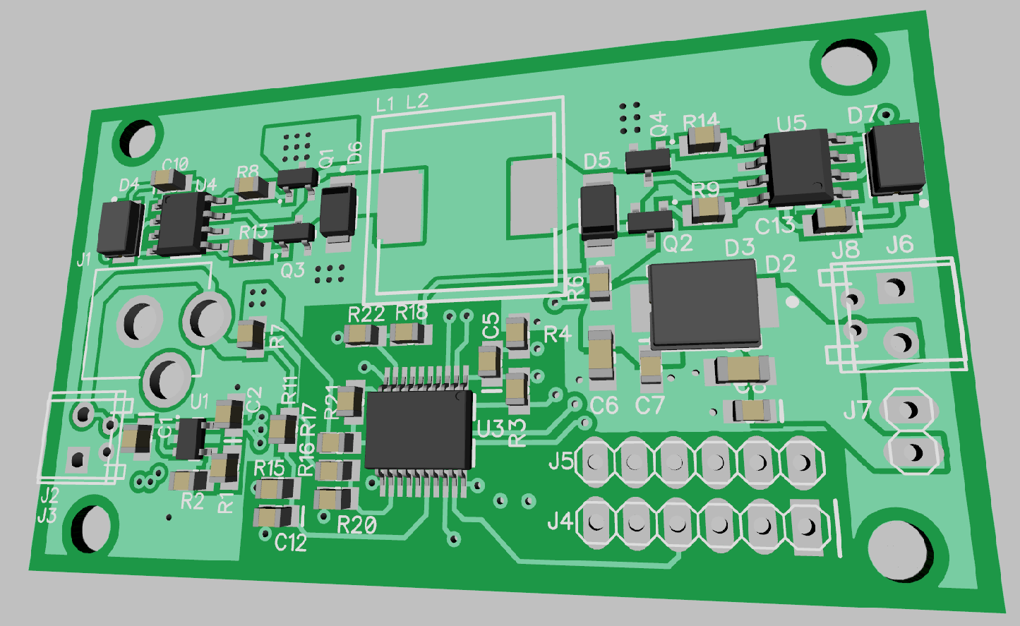
Small update to show you the layout for the V2 board. I changed the topology to be a Buck/Boost converter, as I'm not entirely sure which one I'd like to use. While the buck converter works just fine, it would fail to allow lower voltage higher-current solar panels to charge higher voltage sources, such as a 12V battery. This new version also has input and output over-current protection, which eliminates the need for the fuse which would blow too slowly anyways.
As long as the supply can output 5W as designed, we're looking at approximately $0.46/W.
At any rate, here's what the board currently looks like (some of the 3D models are missing).

 Jonathan Bruneau
Discussions
Become a Hackaday.io Member
Create an account to leave a comment. Already have an account? Log In.
Did you use the RT8299 as buck ?
I'm curious about test data ..... pwm control the enable pin ?
Are you sure? yes | no