As part of my weekly routine, I run a Digikey search in the "Voltage Regulator" and "Voltage Controller" sections in hopes of finding a better, cheaper alternative to the RT8299. I even have the searches saved: try them out if you're interested:
Why looks for a new regulator? Why hate on the RT8299? Because it tempts me.
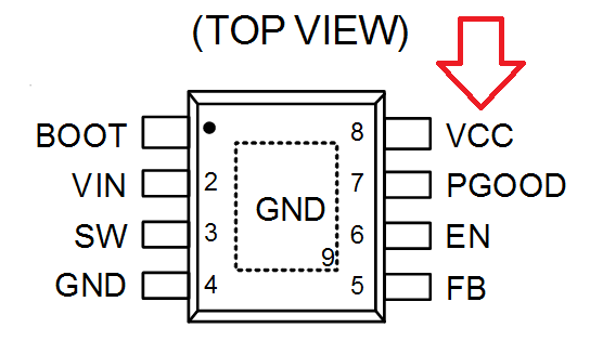
Here's why. Take a look at the pinout of the RT8299.

See the VCC pin? Well, dig deeper in the datasheet and you'll find that this pin is actually the output of an LDO.

For the astute (and long term memory) observer, my latest and greatest hack of this RT8299 requires an external LDO regulator to power the PIC MCU used to override the default behavior of the RT8299 (see this post if your memory fails you).
Given that the RT8299 has a LDO built in, and it's exposed to a pin... well damn, I "should" be able to use it and rid myself of this unholy external LDO! Yoohoo!
"Should" is the correct answer. The RT8299 fails us in two ways.
- The RT8299's internal regulator only powers on when the EN pin is high.
- The voltage coming out of the regulator is said to be 5V, but goes all the way to 9V as VIN rises.
I like how the datasheet discretely fails to mention point 2.

To make things worst, with the enable pin always high, there's no way for me to properly stop the RT8299. Stopping the regulator is crucial to sample the open-circuit voltage (Voc) and to prevent an over-voltage condition on the output.
This is where those weekly Digikey searches come in.
As part of my weekly ritual, I peruse the datasheet of new parts that crop up to see if anything juicy strikes my fancy. About a month ago I landed on this guy: the AP65452.
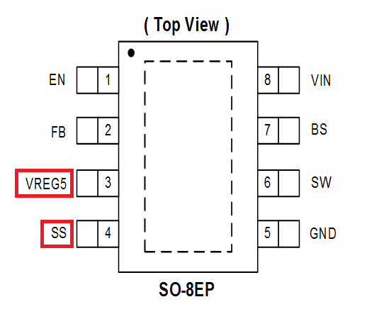
The specs aren't perfect, but the pinout certainly is: a stable 5V VCC, and a soft-start pin, exposed!

For the uninitiated, the soft-start pin usually connects to a capacitor and is charged with an internal constant current source. This voltage is then used to limit the rise time of the output of the regulator. All in all, it eliminate large inrushes of current, and that's a good thing.
It's especially a good thing since the 5V regulated output is, like its RT8299 cousin, only enabled when the EN pin is high. This means I cannot use the EN pin to start/stop the regulator. But thanks to the soft-start pin, I have an alternative way to keep the AP65452 disabled. With the help of a single N-channel MOSFET, I can keep the soft-start voltage close to GND (i.e. prevent the capacitor from charging) to prevent the AP65452 from turning on.
Now we're cooking with oil! The regulator can power up, enable the internal LDO, and stay off until the MCU wakes up and is ready to go.
This had enough legs to run, so I made a board and tried it out.

The same OpAmp feedback pin override technique was used to adjust the maximum power point, and it worked as expected. Horray!
Is the AP65452 the final solution? It depends. It's Vin range is smaller than the RT8299 (4.5V-18V vs 3V-24V) and the maximum output voltage is 6V, hardly enough to charge 12V batteries.
Do I need to care about 12V output? Maybe this is something you can tell me.
 Jonathan Bruneau
Discussions
Become a Hackaday.io Member
Create an account to leave a comment. Already have an account? Log In.