A long time ago (man, almost 1.5 years ago) I tried my hand at a SEPIC, with mixed results. While the topology indeed works as a MPPT, the two inductors required by the topology made the cost quickly go out of budget (switching at 31kHz). So, I canned the idea.
But after reflecting on the findings of my latest MPPT hack, I started thinking about the SEPIC once more. This latest hack works quite well, but suffers from a fatal flaw: the maximum output voltage can only go up to 6V. There are a lot of applications out there that require a 12V output, so 6V just wouldn't cut it.
I needed something that could output 12V, and in the spirit of this project, could output 12V irrespective of the input solar voltage (lower or higher than 12V). This naturally brought me back to buck-boost topologies.
So I started looking for boost or buck-boost regulators that could be hacked into MPPT controllers. The results were not encouraging. I found that in my price range, the regulators were one of more of the following:
- Unable to output enough current.
- Too expensive.
- Switching too slowly, requiring large inductors.
- Too inefficient
And on top of using hacking a regulator, I would still need a MCU to start/stop the regulator for Voc (Open-Circuit voltage) sampling, crucial in finding the MPP.
This is when I started turning my brain on.
Hey, if I need to have a MCU anyways, it would be a hell of a lot cheaper to replace a hacked-up regulator with a MOSFET (cheaper by an order of magnitude) and use a SEPIC as long as it was switched fast enough to keep the inductor sizes small (a.k.a. within budget).
How fast? Well, pretty fast actually. Anywhere in the 300kHz to 1MHz range. I made a spreadsheet to calculate exactly how fast I needed to go, using equations given from three reputable vendors. You can see it here (or just look at the pretty picture below).
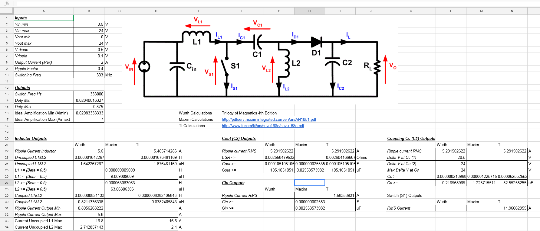
333kHz seemed to be as slow as I was willing to go, which gave me a 1.6uH inductor size. To my surprise, the amount of output decoupling is enormous, 105uF @ 333kHz! At 500kHz, that value thankfully went down to 70uF.
The key at this point was finding a MCU that could generate a >= 300kHz PWM signal with sufficient resolution at a price point lower than using an external boost regulator + MCU. I say sufficient resolution because with most (if not all) PWM peripherals, as the period decreases (i.e. increasing frequency), the number that can be used to represent the duty cycle also decreases. The fewer bits available, the coarser the MPPT becomes. If too coarse, the MPPT cannot successfully settle on the actual MPP. I ran into this issue in the past and talked about it in this blog post.
Turns out finding a sub $0.60 MCU that can switch at such high frequencies while retaining sufficient duty cycle precision is quite hard. I only found a handful:
- PIC12F1571
- PIC16F1764 (over budget)
- ATtiny25
- XMC1100
- XCM1301
- EFM8BB
- <insert your suggestion here>
Factor in other variables such as:
- The design needs to have at least 1 comparator, preferably 2.
- The design needs an OpAmp for over-current sensing.
- The design costs can be reduced if the external MOSFET driver can be replaced with MCU GPIO pins.
- The MCU needs to have a ADC for Voc sampling and tracking.
- I just want to prototype the damn thing at this point.
And I ended up using the PIC16F1764. The integrated OpAmp + 2 comparators + 16bit PWM operating at 32MHz + 100mA (not a typo) high current drive MCU pins + the fact that I already have some lying around tipped me over. For a 333kHz oscillation, I would end up with a period value of 96, meaning I would have 96 discrete steps for duty cycle. With a max of 24V input, this would give me a resolution of:
I found this acceptable enough to bother making a PCB for it. Here it is, in all it's glory.
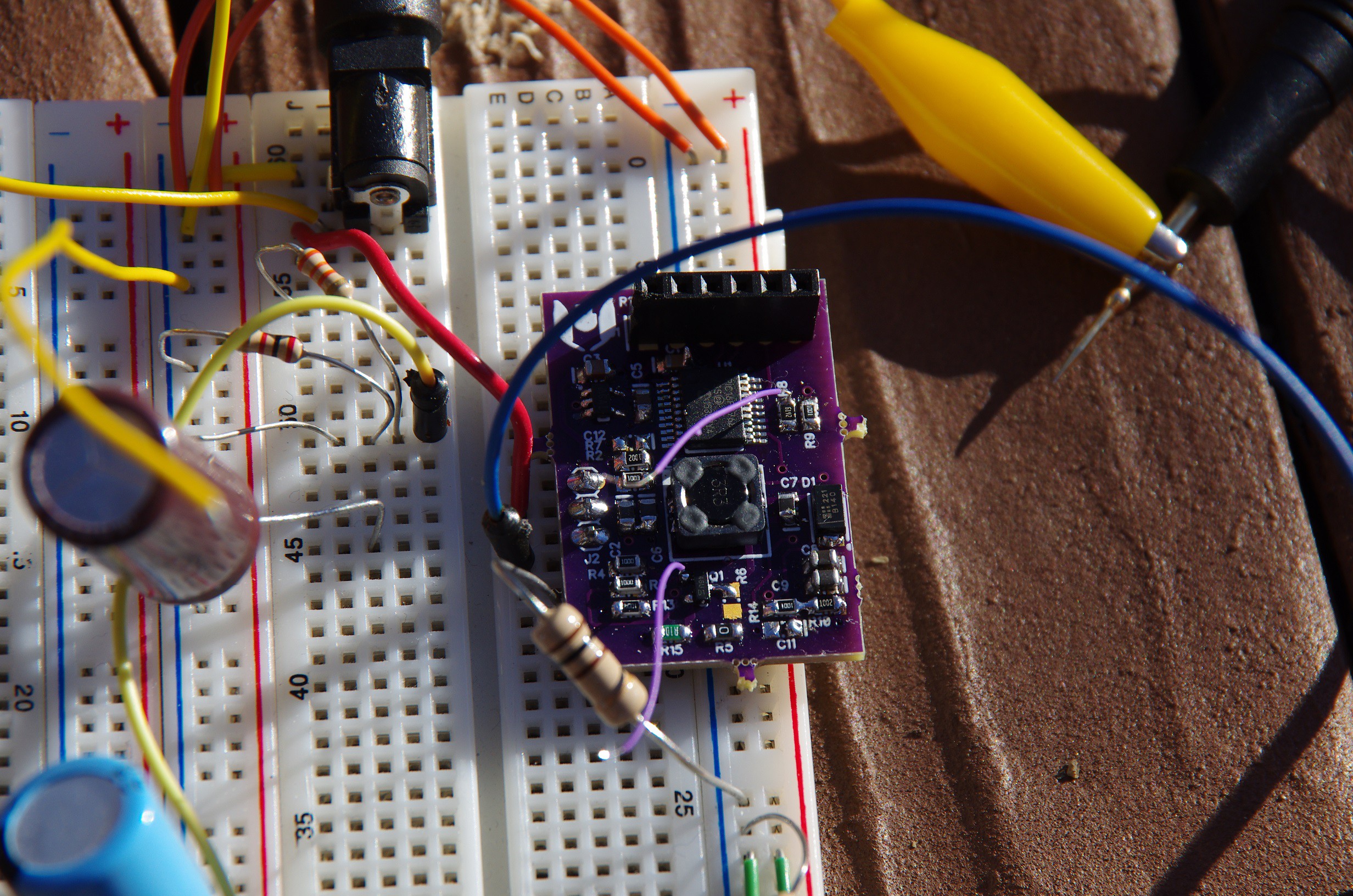
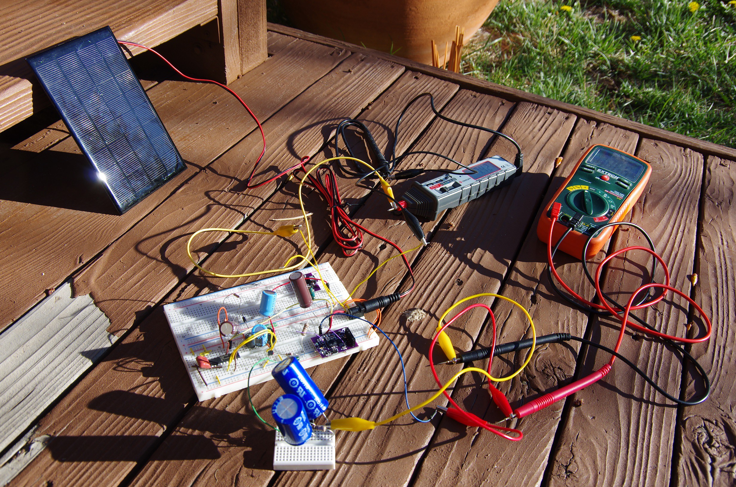
I ended up using a slightly larger inductor than calculated in my spreadsheet to give me a margin of error. I used SRF0703-3R3M, a 3.3uH coupled inductor. (The astute observer will also notice that I actually used a PIC16F1768, but that's a complicated story that's not relevant for this blog post).
This SEPIC works in fact quite well. I cheated just a touch though: I'm switching at 333kHz but the output capacitance is only 44uF as opposed to the 105uF. It seems to be working fine, so I don't know what the additional 61uF would do extra. Call me blissfully unaware.
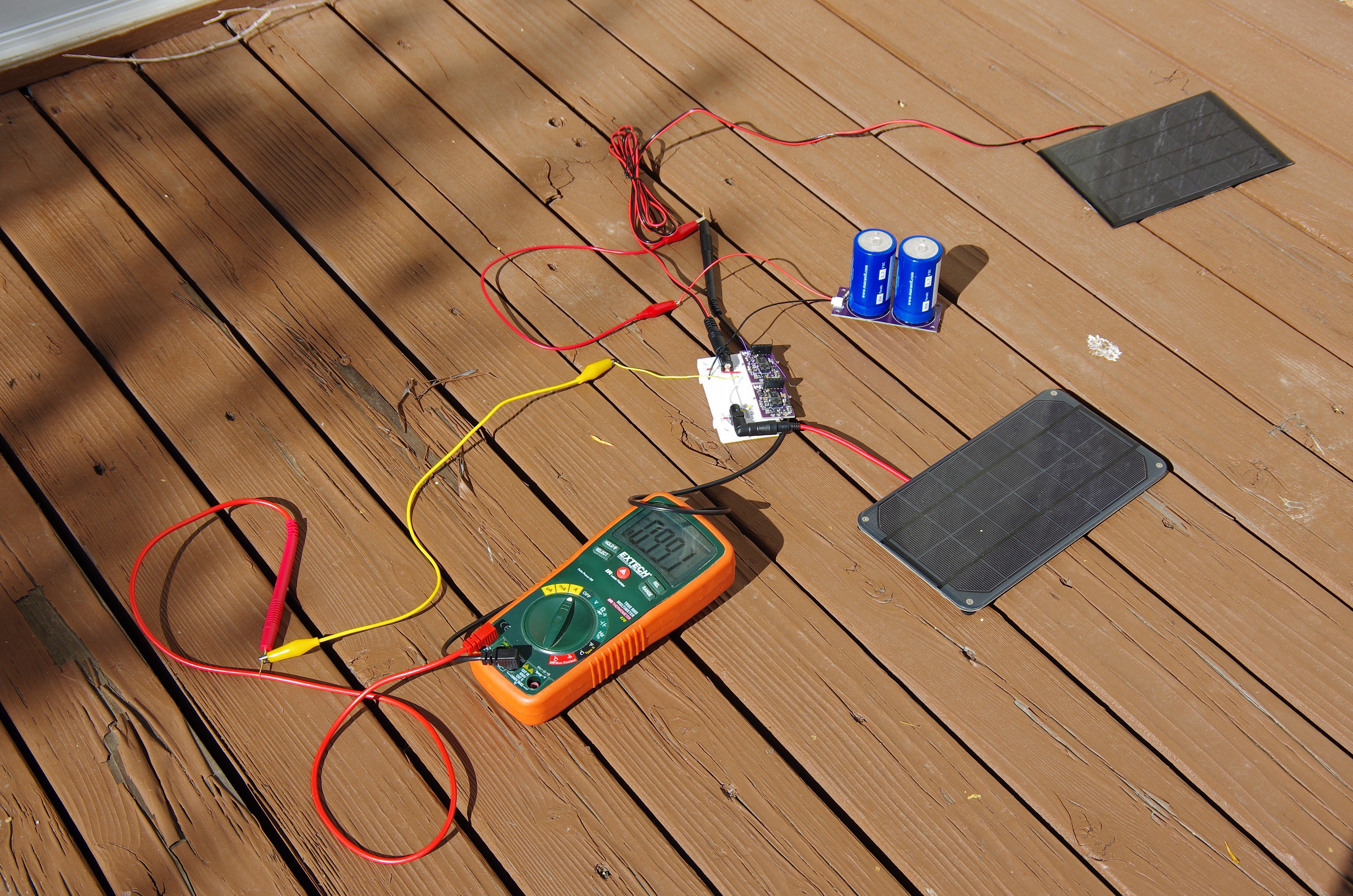
I took this SEPIC a step further and build two more to see how they behaved in parallel. I'm pleased to say that they parallel quite well. The pictures below illustrate two different solar panels of different MPP voltage working in parallel, each delivering about 0.5A for a total of 1A.

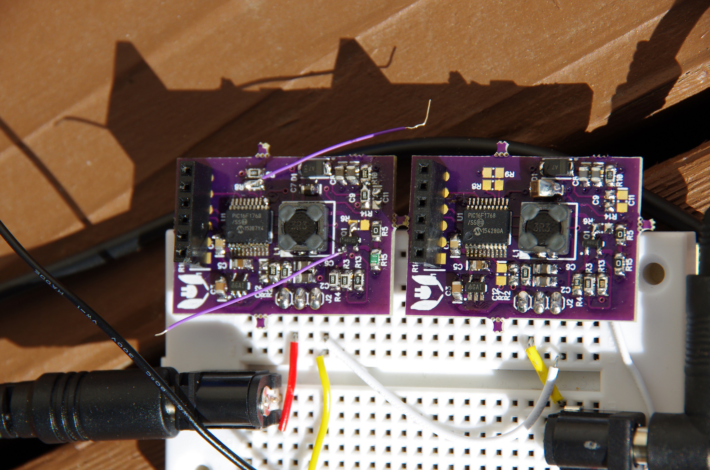
I'm really happy with the way this endeavor turned out. If it weren't for the pricey PIC16F1764 ($1 @ 1k), I'd call this design done. f there was something equivalent at half that price I would declare victory. The trick is the over-current protection. If I took that out, a cheaper solution would be readily available.
I'll be on the lookup for a cheaper MCU, but could use your help. Feel free to leave a comment or send me a PM with any suggestions you may have.
 Jonathan Bruneau
Discussions
Become a Hackaday.io Member
Create an account to leave a comment. Already have an account? Log In.
STM32F030F4 (48MHz ARM cortex M0) is around $0.44 a piece at QTY 10 from China. I use this part a lot for my projects here. https://hackaday.io/project/9469-misc-arm-projects
You can increase the PWM resolution by dithering. i.e. change LSB of PWM duty cycle on a cycle by cycle basis. On ARM chips, this can be done using DMA so using very few CPU cycles.
www.st.com/resource/en/application_note/dm00119042.pdf
Are you sure? yes | no