Mike Cochrane
-
Sea Trial Two update
07/08/2015 at 09:35 • 2 comments"Sea Trial" two has been going on since Sunday 14th of June. I installed two units, one on a buoy at St Heliers Beach and one at neighbouring Kohimarama Beach. The two units are slightly different, one has the same external antenna used in the first trial, the second has an internal antenna. The intention of this difference was to confirm if the signal strength was going to be sufficient without having to put another hole through the waterproof case.
See the results:
The battery life issue is solved!
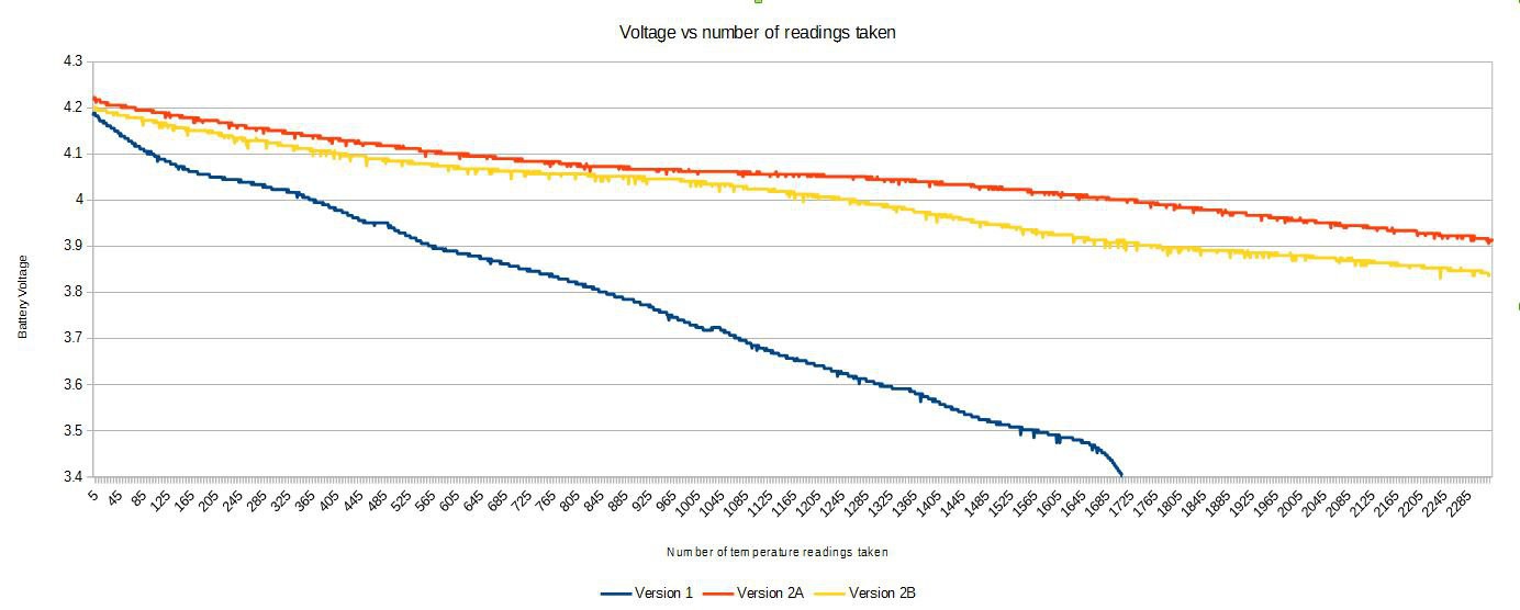
The changes between version one and two to extend the battery life have been more successful than I expected. Trial one lasted 12 days (sending 6 updates an hour) before the battery voltage dropped below 3.4v and it stopped transmitting data. Trial two both units have been running for 23.5 days (sending 4 updates an hour) and the battery levels are at 65% and 56%! So it looks like I'm going to get nearly four times the battery life this round!
Here's a graph of the battery voltage vs the number of readings the unit has sent back:
I'm guessing the difference in voltage between the two units is to do with the life history of the batteries. They were all out of my parts drawers and have had different uses and abuses in the past.![]()
Waterproofness
When I retrieved the unit after the first sea trial it wasn't 100% dry when I opened it. I wasn't sure if this was because it was damp when sealed or if water got in while deployed.
Yesterday as I was out swimming I checked on the unit installed at Kohimarama beach. It has was appears to be 2ml of water inside the enclosure. I've left the unit out, the way it's setup there's a margin inside the bottom of the enclosure without any electronics so the water is not directly impacting anything yet.
What's next?
I'm going to leave both units out until the batteries go flat or the water ingress gets too extreme. In the mean time Version 3 is underway, so far the only change is to add a light intensity sensor and start logging this too. When I close it up I'll add some O-ring grease (same as I use on my camera housings) and see if this helps the seal.
Got any ideas on other sensors to add? I2C or SPI.
-
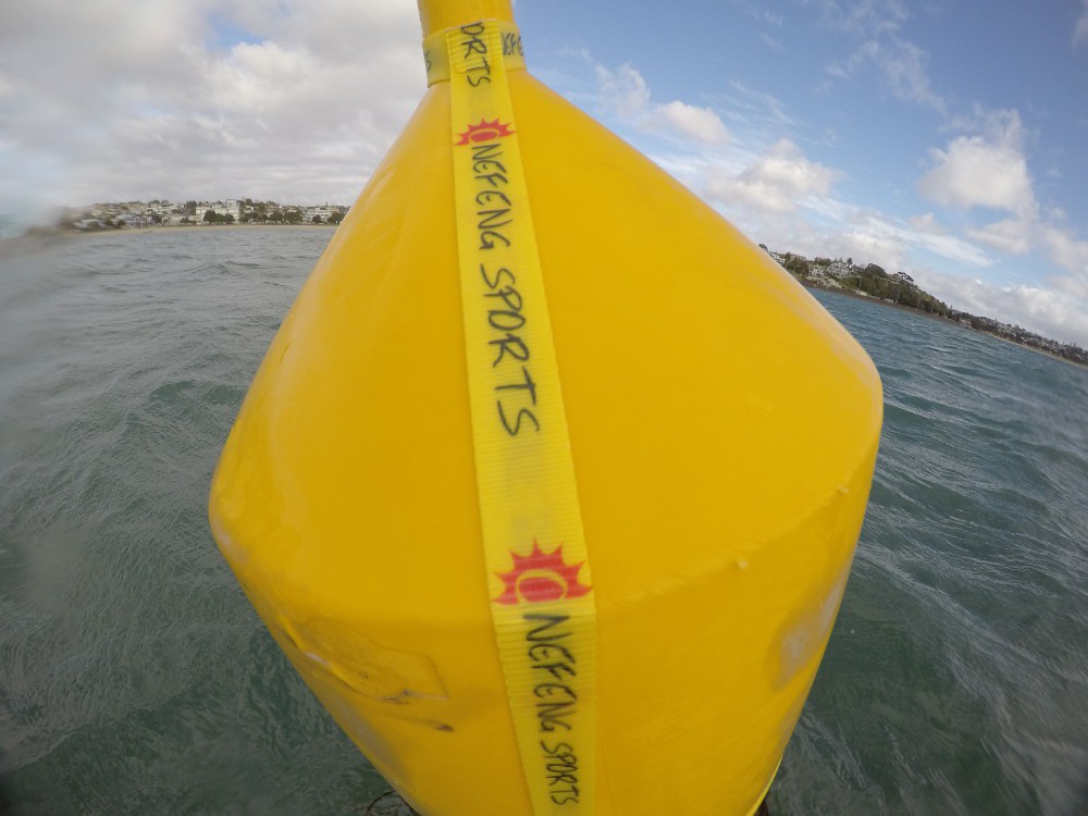
Version Two: Proper mounting straps
06/20/2015 at 11:08 • 0 commentsVersion one was tied to a "5 knot" marker buoy with some string:
![]()
This was effective, but not ideal. There's no way to remove the sensor without undoing everything. It's hard to tie knots when you're bobbing around in a wetsuit in the water. And it just doesn't look good.
So time to find something better!
How big does it need to be?
I've never swum out with the ruler to measure how big the marker is, but i figure they must be a "standard" size, right? So much Googling later, yeah there's not really a standard size for these in NZ. But they they look almost exactly like the "Marker Buoy 400" from an NZ company. They website has a handy drawing:
![]() I "verified" a couple of measurements by using hand spans while out swimming one day and it all matched up. The below the waterline section is different but that doesn't affect me.
I "verified" a couple of measurements by using hand spans while out swimming one day and it all matched up. The below the waterline section is different but that doesn't affect me.What to make it out of?
I need it to be kinda stealth (still haven't work out if I'm allowed to attach to the marker buoys) so needs to be yellow. I tried to buy some yellow webbing from my normal sources, 100m rolls was the shortest I could order as it's not a standard color. I don't need 100m :-(
I was also going to need a buckle of some sort, what has 25mm webbing and a solid buckle? Kayak tie downs, and they even come in yellow! Someone had bought some Multi-purpose Tie down Straps into NZ so I bought four for less then I could have paid for the webbing alone. I also got some polyester thread for my sewing machine so it didn't rot like cotton might.
Putting it all together
Maintaining the same basic idea as the tied version. A loop at the top, a loop around the middle with the buckle in it, and a vertical length between them. Then some loops and velcro to hold the enclosure firmly but also be removable. 30mins later it was all together and ready to take out and try.
![]() The top fitted great
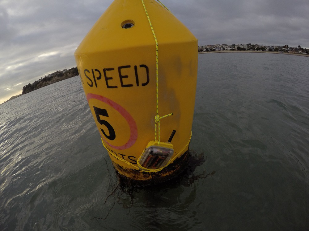
The top fitted great![]() The bottom was a bit high, next version the vertical piece will be longer so the lower loop doesn't cover the words on the buoy. Oh and I printed and laminated some labels and threaded them on the lower loop. The black velcro secures the enclosure very firmly.
The bottom was a bit high, next version the vertical piece will be longer so the lower loop doesn't cover the words on the buoy. Oh and I printed and laminated some labels and threaded them on the lower loop. The black velcro secures the enclosure very firmly.Sea trial two began Sunday 14th June with two units installed, each on different beaches. Both are sending data to http://oceanswims.nz/watertemp
-
Version Two: Stop eating batteries!
06/15/2015 at 09:40 • 1 commentAfter a successful first deployment it's time to work on the battery life.
I already had some ideas for how to reduce the power usage, so time to start working on them:
- Turn the Sim800l off and keep it off
- Hibernate the Teeny 3.0 instead of just delay()
- Reduce the time each send cycle takes
- Kill the blinky LED
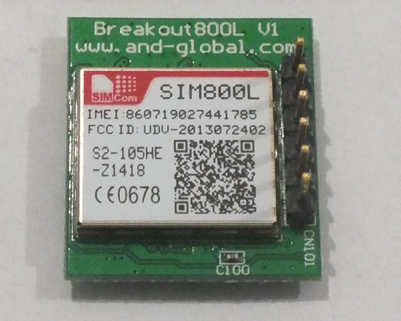
New Sim800l breakout board
The previous breakout board I was using was the only one I could get easily in New Zealand. It broke out pover, ground, Tx, Rx, and Reset. Turns out the Power Key pin is tied to ground forcing the module to stay power on.
After much searching I found an equally simple break out board from AND Technology on AliExpress that gives me the Power Key (PWRKEY) instead of Reset. I ordered three and handed over the extra cash to get the DHL'd (8 days) instead of snail mailed (probably a month).
![]()
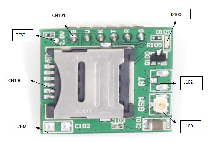
A welcome surprise I got email diagrams and documentation for the break out board in perfect english. It contained one critical piece of information about the PWRKEY pin "Shorted with GND via R104 by default". So I knew I had to remove R104 so I could use the PWRKEY, guess which is the only resistor not labeled on the diagram:
![]() So it's the unlabled one top left, by the 2.8v test point. So that got wiped off with the soldering iron and a 100R resistor from that to a I/O pin on the Teensy.
So it's the unlabled one top left, by the 2.8v test point. So that got wiped off with the soldering iron and a 100R resistor from that to a I/O pin on the Teensy.// Pull PWRKEY low pinMode(2, OUTPUT); digitalWrite(2, LOW); // For at least one second delay(1100); // Then let it go high again pinMode(2, INPUT);
Hibernate the TeensyThe Freescale MK20DX128VLH5 on the Teensy 3.0 has some awesome low power / hibernate modes available. Thankfully [duff2013] is more patient than I and has created an awesome Snooze library for the Teensy.
I added a watch crystal to the Teensy so I could use the RTC, not for the clock but for waking from hibernate.
So
for (int i = 0; i <= 9; i++) {
    delay(60000);
}
Changed to the way more accurate and low power// Update Every 15 mins #define UpdateTime 15 // Sleep #include <Snooze.h> SnoozeBlock config; // Timing elapsedMillis sinceWake; ... void setup() { ... } void loop() { // Reset ms since wake up timer sinceWake = 0; ... do the useful stuff ... // Sleep until next reading uint8_t sleepTime = 60 - sinceWake/1000; // number of seconds config.setAlarm(0, UpdateTime - 1, sleepTime); // how long to sleep for Snooze.deepSleep(config); // go to sleep }This now gave me very reliable 900 seconds between receiving readings, ever if the sim800l was a bit inconsistent with its response time.
Reduce the time things take
A lot of the code for the first version was about getting it working, so instead of waiting for an expected result from the Sim800L there was just a "wait 4 seconds". So time to get some real code in here:
/**
 * Wait for a define length of time for a
 * particular response from the Sim800l
 */
elapsedMillis waitTime;
bool waitFor(String searchString, int waitTimeMS) {
    waitTime = 0;
    String foundText;
    while (waitTime < waitTimeMS) {
        if (!HWSERIAL.available()) {
            // Nothing in the buffer, wait a bit
            delay(5);
            continue;
        }

        // Get the next character in the buffer
        incomingByte = HWSERIAL.read();
        if (incomingByte == 0) {
            // Ignore NULL character
            continue;
        }
        foundText += incomingByte;

        if (foundText.lastIndexOf(searchString) != -1) {
            // Found the search string
            return true;
        }
    }

    // Timed out before finding it
    return false;
}

/**
 * Wait for "OK" from the Sim800l
 */
bool waitForOK() {
    return waitFor("\nOK\r\n", 4000);
}
Now instead of delay(4000), I've got waitForOK(). Turns out some of the responses were coming back in 23ms where I was waiting 4000!With smart waits in place from Sim800l is now turned on for a little over 30 seconds where it was previously on for nearly 90 seconds. This saves a lot of power (the Sim800l can peak at 2A power usage).
Kill the Blinky LED
All the breakout boards have status LEDs on them, they flash at different rates depending on the status of the module. Really handy during testing, not so handy for conserving battery. So the three component top right of the board had to go too. I'm not sure how much this saves, but it seemed worth it.
That's it for power saving changes in this version. Full code is in the GitHub repo.
-
Version One: Sea Trail
06/14/2015 at 12:17 • 0 commentsTime to stick it out in the water!
Software
The code is unchanged from the bench test except for adding an extra 5 minutes to the delay to get ~10 minute updates instead of the 5 minute updates on the bench test.
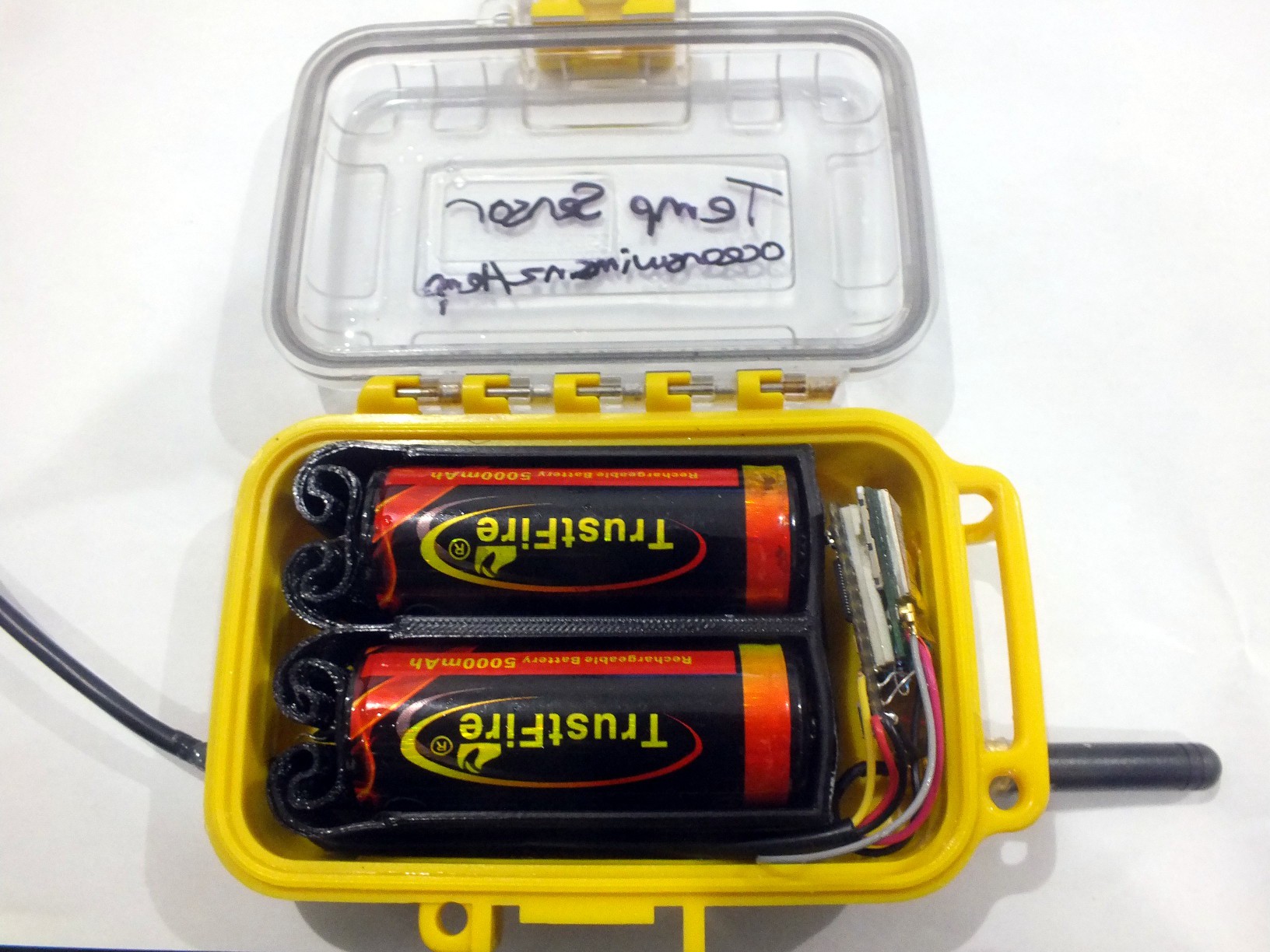
Hardware
The hardware is also basically unchanged from the bench test. It now has two batteries, fresh off the charger, wired in parallel. They are held in a 3D printed battery holder.
![]()
Mounting it in the sea
On Saturday 30th of May 2015 I threw the sensor and some cord in my swim bag and did a normal couple of kilometer training swim with friends. Afterwards Rosie and I swam back out to one of the "5 knot" marker buoys 200 meters offshore and "mounted" it.
![]()
Okay, so "mounted" is a bit generous. It's tied one with some cord, and has some labels scribbled on it so it doesn't look too much like a remote trigger for a bomb.
Test Results
It ran smoothly for a bit over 12 days!
Only a couple of data points were missing (likely GSM connectivity issues). The datasheet said the Sim800L would operate down to 3.4v and that was spot on. It sent three readings at 3.402v, then went quite for a while then one final reading at 3.391v.
A couple of days later a pre work swim allowed me to retrieve it. When inspected then enclosure was not 100% dry, there was some moisture present. I'm not sure if this was condensation from when it was closed up, or if it got in while installed. The gasket wasn't totally clean so it's possible that's how some water got in.
Let's call that a success and time for version two!
-
Version One: Bench Trial
06/14/2015 at 11:26 • 0 commentsBefore installing the first prototype in the sea I wanted to run it for a while to see what the battery life might be and ensure the code doesn't mysteriously die after a period of time.
Circuit
A teensy 3.0 connected to the cheapest Sim800L breakout I could find. This breakout has the Tx/Rx, Power and Reset pins broken out. A simple resistor voltage divider on the Rx input of the Sim800L takes care of level shifting the Teensy's 3.3v to the needed 2.8v IO.
Software
The way the breakout for the Sim800L is wired, the module turns on as soon as it gets power. The plan was to tell the module to power off when not being used then use the Reset pin to bring it back to life. I wrote some quick code, wired up the Reset pin to a digital IO pin on the Teensy and I could turn it off, then reset it to bring it back to life so moved on to the rest of the code thinking this was sorted - more on this later.
Next was making an HTTP request, there's plenty of code examples for making a TCP connection and sending HTTP requests with the Simcom GSM modules. Then I checked the datasheet and found it had HTTP request support build in (why doesn't everyone just use this?). So making an HTTP GET request is pretty trivial, I hacked that up and had it sending me temperatures ever minute shutting down the module in between, it worked okay (code was a mess but worked - optimised for implementation speed?).
Next was to leave it going longer with 10 minute updates. So I changed the delay at the end of the loop and tried it out, first a delay() that long was coming up short, 9 x 60 second delays worked so that's what I used. The first data came through, the Sim800L turned off. All looked good. Then the Sim800l turned back on! I checked the serial debugging, I didn't turn it on! Turns out the way the breakout board is wired it always turns back on about 30 seconds after being powered down. In my earlier tests I was resetting it before it had time to auto start so I didn't find this. Nothing I can do about this on this breakout, so I've got to live with it.
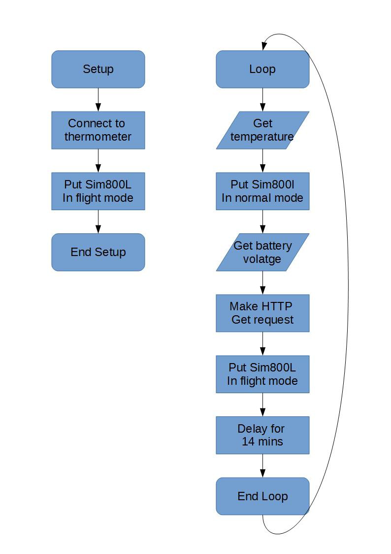
New plan, put it in flight mode when I don't need it - the lowest power mode in the datasheet that I could use - then put it back in normal mode when I need to send data. So that's what I did:
![]()
Test results
Everything worked fine! I set it at ~5 min updates and gave it a single half used battery and left it running for a couple of days outside in the rain and wind.
Extrapolating the battery voltage drop to two fully charged batteries and ~10min updates suggested 10 days battery life was possible. That was good enough for now, time for sea trials!
Sea Temperature Sensor using GSM
A template for battery powered sensors using GSM

 The top fitted great
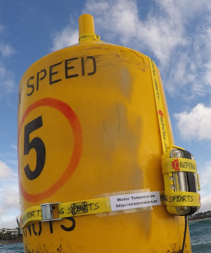
 So it's the unlabled one top left, by the 2.8v test point. So that got wiped off with the soldering iron and a 100R resistor from that to a I/O pin on the Teensy.