-
Raspberry Pi LoRaLAN gateway for Vinduino
12/24/2016 at 17:00 • 0 commentsLoRa Sensor Gateway
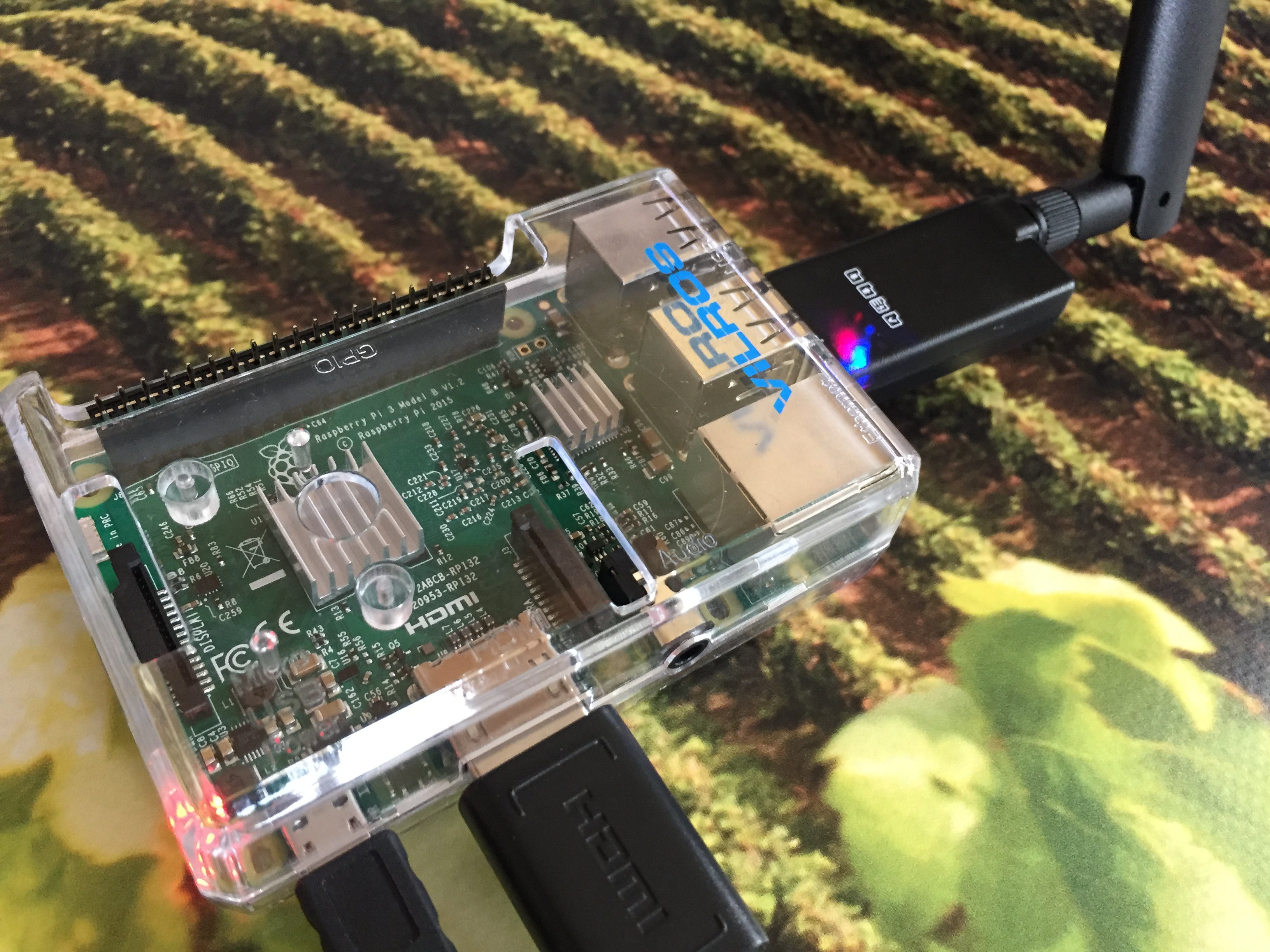
The Vinduino gateway receives LoRaLAN sensor data from the Vinduino sensor stations and forwards via WiFi to a ThingSpeak account.
To date, the Vinduino project has been using an Electric Imp solution, which required some soldering and PCB assembly.The following project update, describes a gateway that uses a LD20-H USB LoRa dongle from Globalsat, and does not require any electronics tinkering. This dongle is basically a USB version of the Globalsat LM-210 LoRa module used in the Vinduino sensor station, and, alike the module, works as a wireless UART. Combined with a serial terminal program, this dongle also makes a great debug tool to check out the LoRa network and sensor stations.
The Vinduino LoRa gateway can handle up to 300 sensor stations within a range of 5 miles, and can be made for less than $100, assuming that an old PC’s useful life can be extended for the task of working as gateway. Because the software is based on the operating agnostic Python-3 programming language, the supported PC platforms that can function as gateway include Windows, MacOS, Ubuntu Linux , and of course Raspberry Pi. For increased traffic handling, more USB dongles can be added, working on different frequencies.
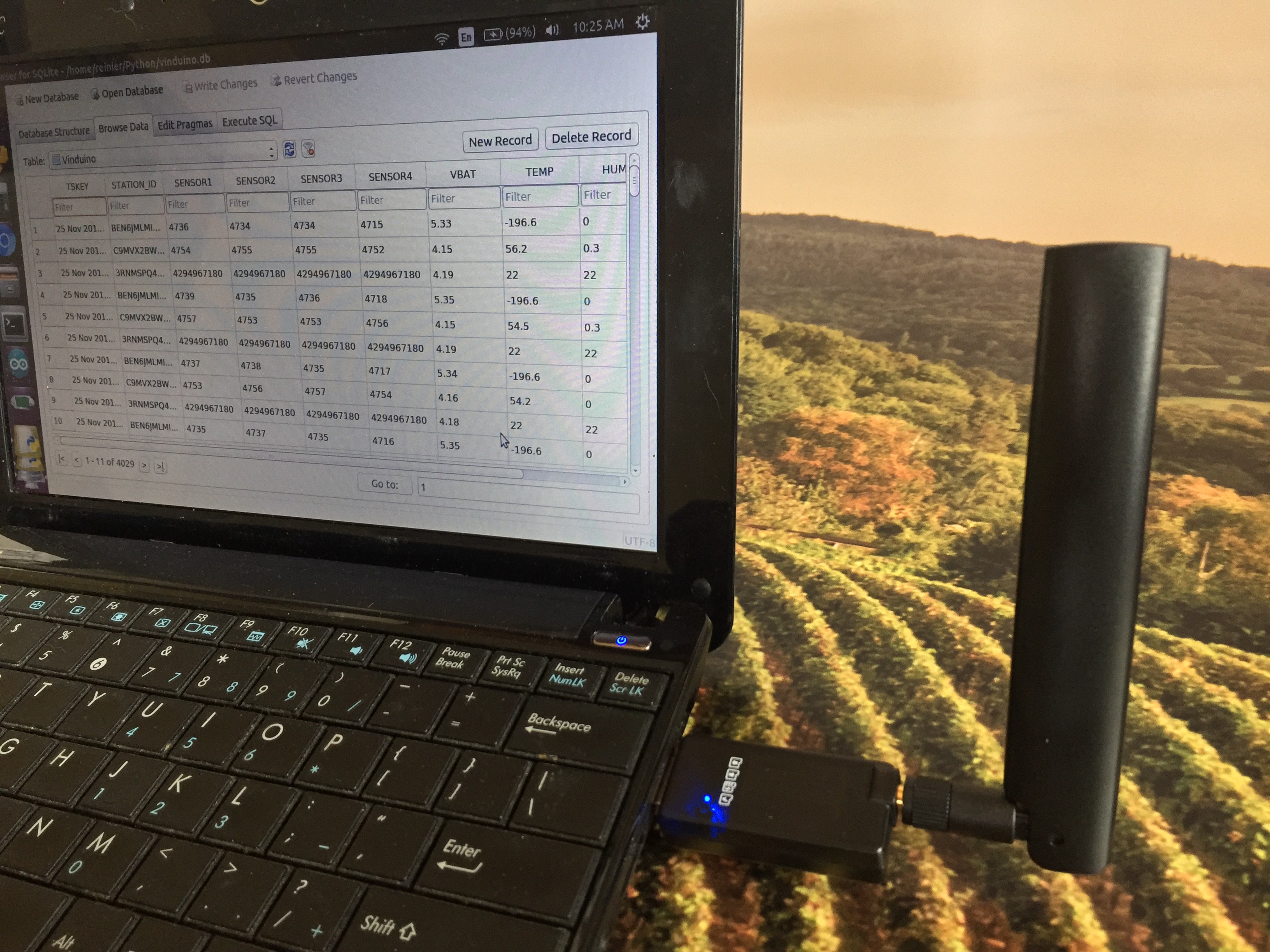
The Python-3 gateway script, although tested to be working reliable for its basic gateway function, can be customized/improved as needed. For locations where access to Internet is not reliable, or intermittent, we added a SQLite database to store all sensor data locally.
One possible application could be to store data locally and upload when an internet connection is available. This may also be a good starting point for developing smart irrigation algorithms.
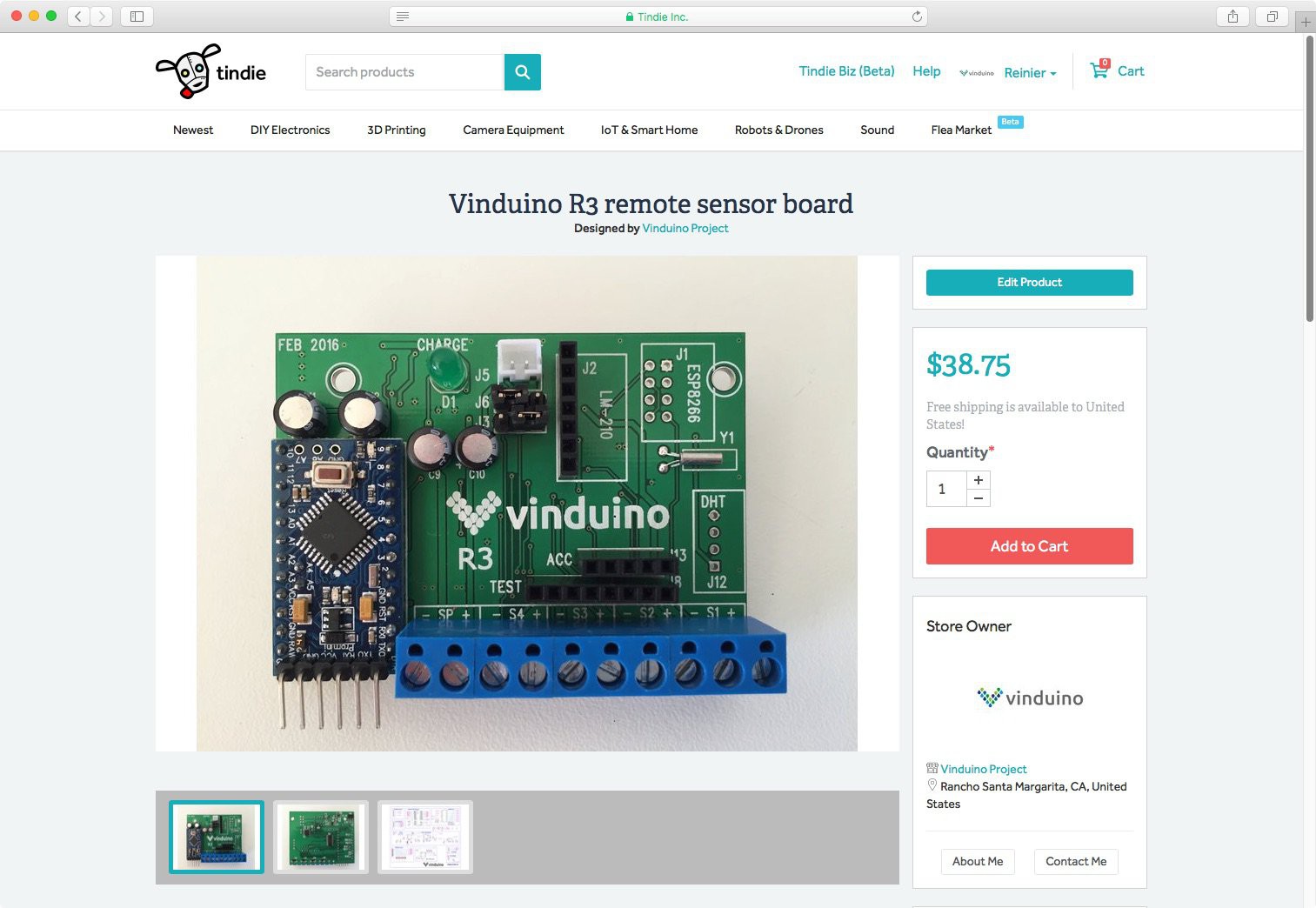
The Globalsat LD20-H is available on Tindie
PS: This LoRaLAN gateway is not compatible with LoRaWAN sensor stations.
LD-20H features
- Ultra-high sensitive receiving ability by LoRa spread spectrum modulation technology
- Long-distance transmission (1KM to 10KM)
- Easy to use and easy to configure
- Multiple dongles for multi-channel gateway
- Programmable parameters:
- Frequency: 862-1020 MHz
- RF data rate: 0.81K, 1.46K, 2.6K, 4.56K, 9.11K, 18.23K bps
- Max TX power: 5-20 dBm (100mW max)
- UART baud rate: 1200-57600 bps, parity non, odd, even
Installation
Python modules needed for the Vinduino gateway script:
- serial
- time
- thingspeak (linux install: $ sudo pip3 install thingspeak)
- sqlite3
DB browser for SQLite (http://sqlitebrowser.org) is a great program to manage the SQLite database.
Linux install: $ sudo apt-get install sqlitebrowser
For Windows, install the Cypress USB serial driver
For Linux:
Linux does not require a special drivers for the USB serial interface, however ensure that you have qt4, gcc, and libusb installed. The USB driver stack in Linux has a built-in driver for CDC-ACM class devices. The Cypress chip inside the LD-20 supports CDC-ACM class, CDC-ACM driver gets automatically bound to the device and creates a device node in /dev/ttyACM*(* -The name of device node will vary based on the number of devices connected).
Here is a good description for testing the USB serial connection in Linux:
I found that Ubuntu and RPI recognized the USB serial port, but assumed it was an AT-command modem.
A solution that worked for me is to bypass the ModemManager:
sudo systemctl mask ModemManager.service
-
Vinduino LoRa LAN Gateway
09/24/2016 at 22:20 • 0 commentsThis project log entry covers the LoRa gateway that receives and forwards data from Vinduino sensor stations to the ThingSpeak website where it can be displayed as graphs.
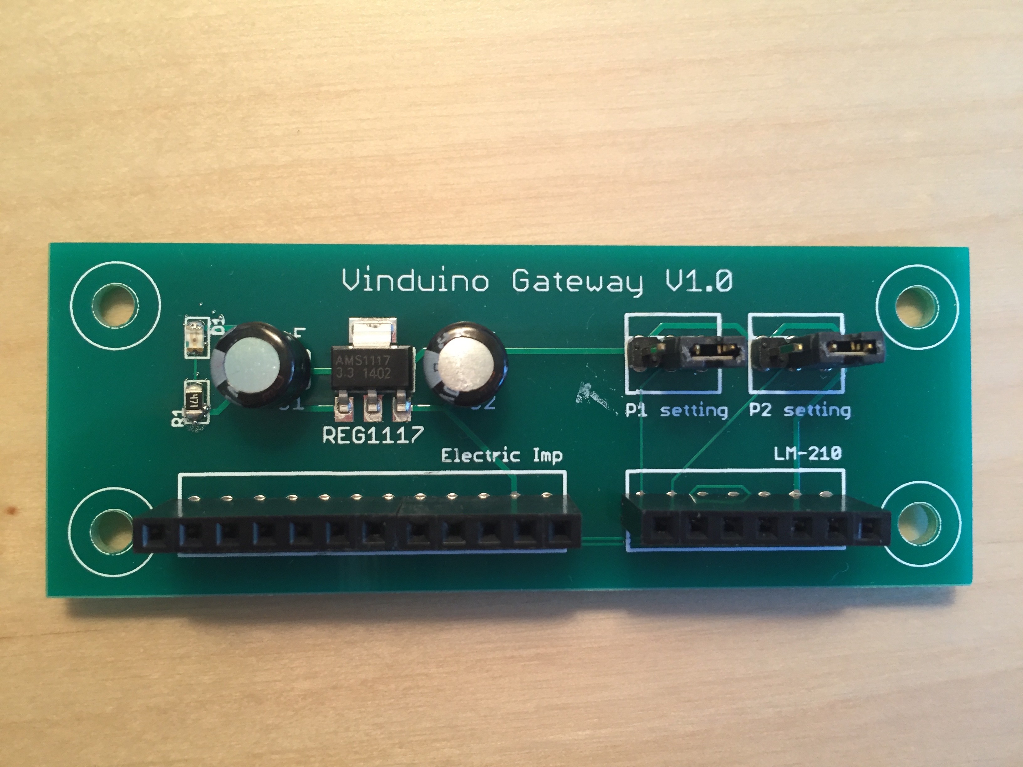
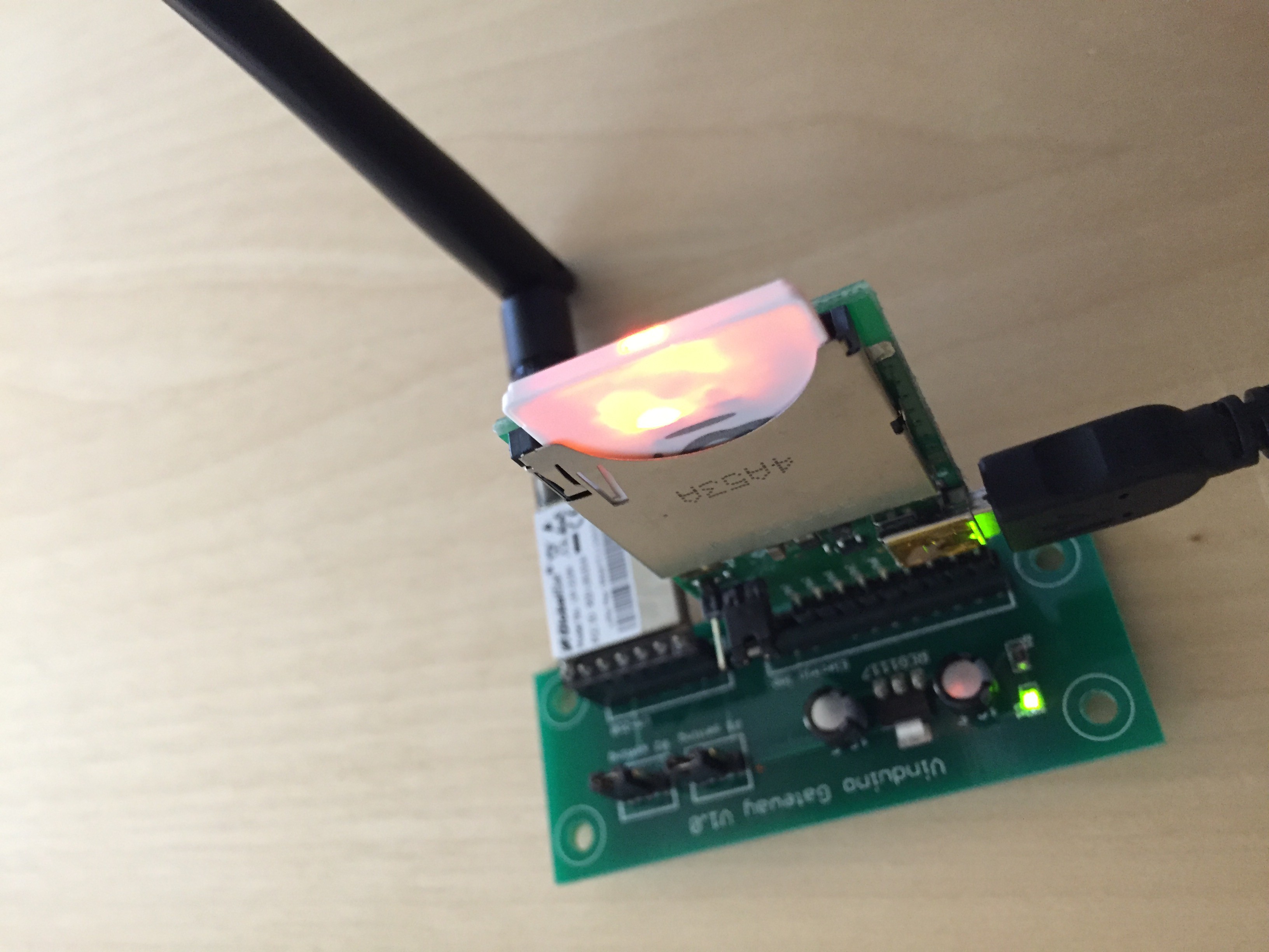
The gateway is based on the Electric Imp 1 and the matching April development board. Other components include a Globalsat LM-210H LoRa radio module, antenna, and Vinduino Gateway PCB. The unit works fine with a regular 5V USB wall adapter as power supply.
During this year's field trials we were able to make reliable data connections over a distance of up to 7 miles (10 km) under line of sight conditions.
As the Vinduino gateway is only receiving data, range can significantly be increased by using directional antennas without violating FCC regulations. The sensor stations (transmitting) only use the FCC approved antennas.
The Vinduino sensor stations are default set to 15 min transmission intervals. This allows for a max of 300 sensor stations to be supported by one single gateway, provided there is collision avoidance in the software.
We tested with multiple gateways and multiple stations this Summer in Temecula wine country, and found no issues with multiple gateways simultaneously receiving data from the same sensor station. The ThingSpeak network server accepts the first message and rejects identical messages coming within 15 seconds.
Components
The gateway is based on the Electric Imp 1 and its matching April development board, available at Amazon.com for around $20.
Other components include a Globalsat LM-210H LoRa radio module, antenna (available at Tindie.com as add-on option for the Vinduino sensor station board), and Vinduino Gateway PCB, available at OSHPark at this link: Order board
The unit works fine on a 5V USB wall adapter as power supply.Programming
Before you can program the unit, you will need to set up an account at electric imp and connect the electric imp using their interesting "Blink Up" procedure. The Electric Imp website has an excellent tutorial, so no need to elaborate here.
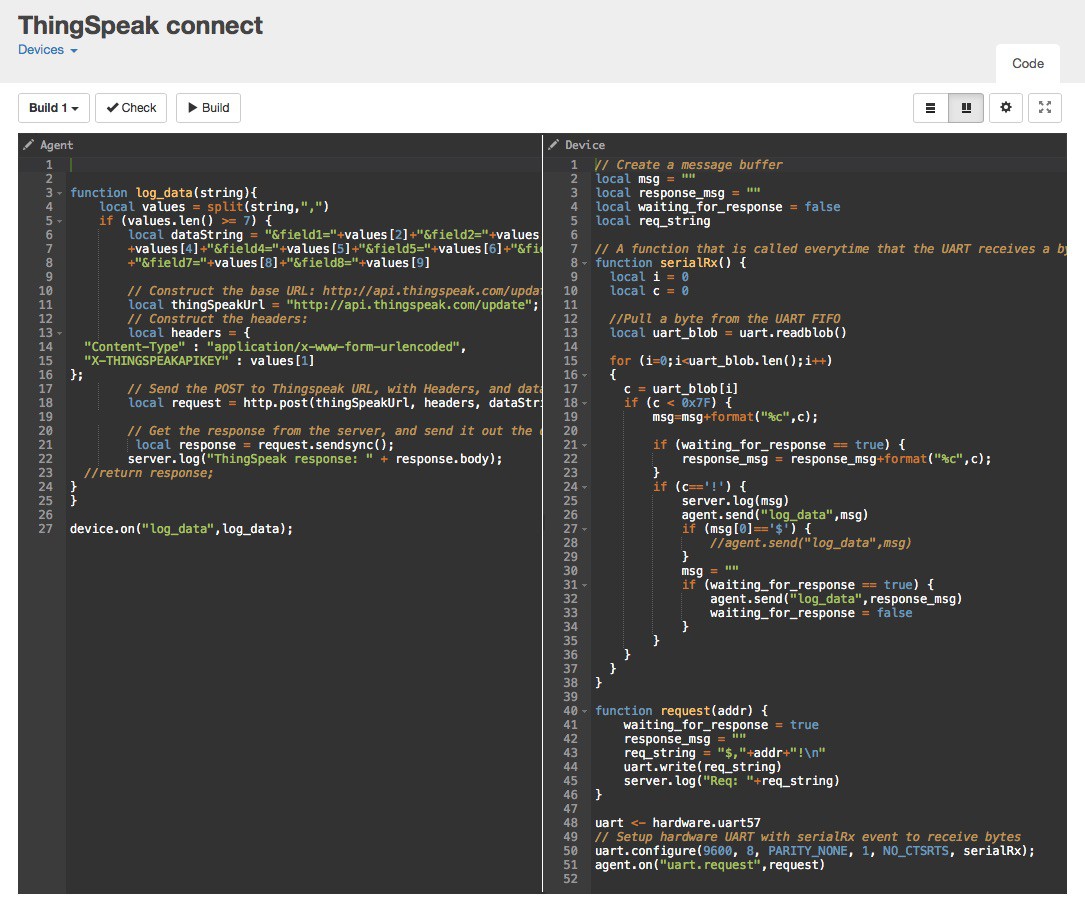
The editor is on line. You can change the software on-line and then activate it to run without physical access to the unit. There is a programming section that runs on the host system of electric imp (Agent), and there is a programming section for the device itself.
The latest code can be copied and pasted from the Vinduino Github page: Vinduino-GW
Luke Beno (analog.io) was the original author, and he kindly agreed to release it to the public domain.
I modified his code to make it work with ThinkSpeak.Testing the gateway and monitoring
The Electric Imp editor has a logging window that is very useful for the initial bring-up and monitoring of the gateway and stations data. As shown below, the device section displays the data as it is received from the sensor stations.
The sensor data comes in readable format. After the channel ID (blurred out in the picture below, there are 4 data fields for soil sensor 1-4, battery voltage, temperature, and
When received and processed correctly by the ThingSpeak server, there is a response from ThinkSpeak with an incrementing number representing the number of correct data lines received for that particular ThinkSpeak channel.Results
We tested during a full growing season in the Temecula wine region this year with 20 Vinduino sensor stations and 10 gateways, all operating at 915 MHz. Most of the issues encountered were related to the soil moisture sensors and their installation, not the sensor stations or the gateway. Although the 915 MHz ISM band is heavily used, we have not experienced interference from other users.
The use of LoRa technology without the overhead of the full LoRaWAN stack can be sufficient for use cases that only need monitoring of non-confidential sensor data over longer distance. For secure bi-directional communications, LoRaWAN may be a better option, but -as always- this comes at higher cost and complexity. -
Selling on Tindie!!
07/28/2016 at 02:20 • 0 commentsRemoving one more obstacle for growers to save irrigation water and cost. We are selling online!!
Vinduino remote sensor platform optimizing agricultural irrigation https://goo.gl/QRyVNu -
To Spray or not to Spray? Adding Anemometer
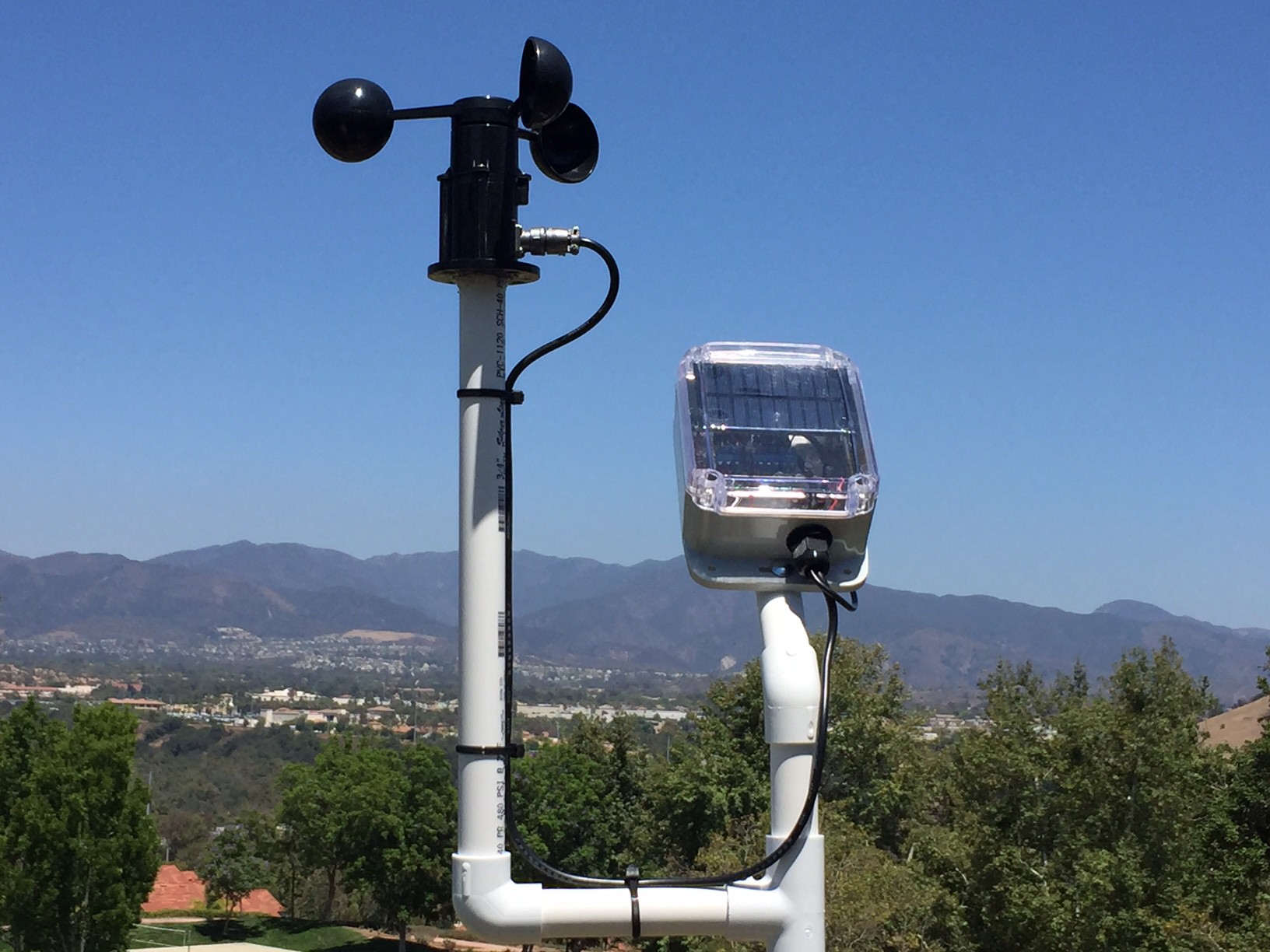
07/17/2016 at 21:12 • 0 commentsFor farmers who have remote fields, it's critical to know the wind speed conditions before setting up the equipment and riding out to spray. Too much wind , and you cannot accurately deliver the "goodness". Basically wasting time and materials and risk contamination of the surrounding properties.
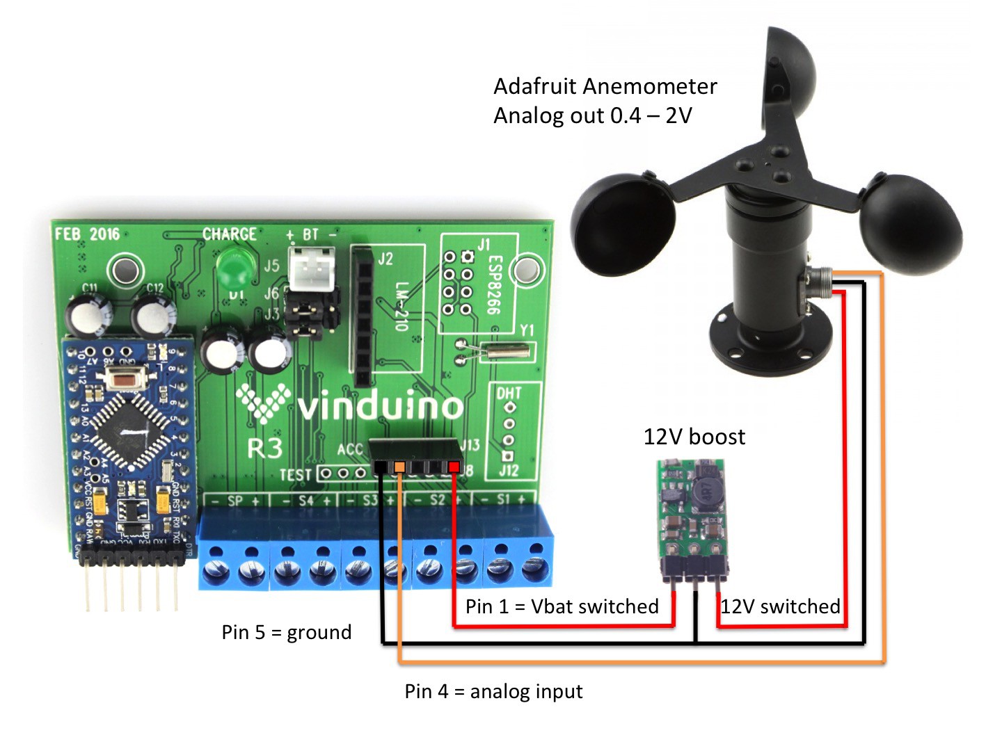
Luckily adding a wind speed sensor ( anemometer) to the Vinduino sensor station is an easy task. We used an Adafruit active anemometer with an analog output or 0.4 - 2 V. There are also passive anemometers with an intermittent contact interface. I prefer the active model as an analog read can be done very fast, and that helps to save battery power. The anemometer requires 12V or higher to operate, and the Vinduino station works with a single 3.8V Li ion battery.
So we added an external DC/DC boost converter module. For this example, we used a low cost SMAKN 5V to 12V module, available at Amazon.
To save battery power, the Vinduino system is kept in sleep mode until the RTC wakes it up. The Arduino then runs through the sensor measurements and sends the data via a LoRa radio modem to the Internet. We do not need to keep sensors powered on during the sleep period.
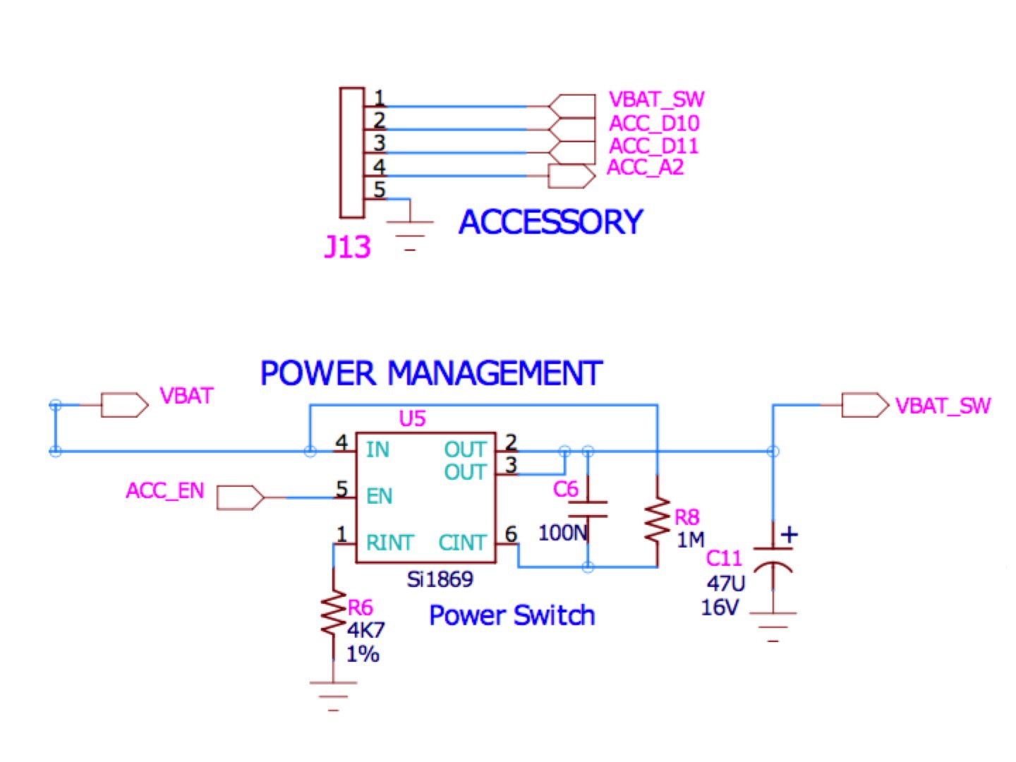
The Vinduino board has a load switch chip that can switch battery power to the accessory connector J13. The load switch is controlled using Arduino digital pin 13 (ACC_EN).
See Github for the full Vinduino schematic diagram. Below shows the simple wiring diagram for connecting the boost converter and anemometer.
The anemometer electronics take about one second to start up and stabilize after power is switched on.
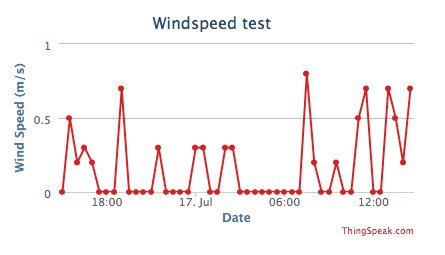
Windspeed calibration is taken from Adafruit data that 0 m/sec = 0.4V out ,and 32.4 m/sec at 2V. Because there is a small temperature drift, the wind speed < 0.2 m/sec s reported as 0.
Here are some initial results. So far, we only had moderate wind speeds during testing.
-
50% Irrigation Water Saved at Veraison
07/09/2016 at 18:32 • 0 commentsVeraison is here in Temecula!!
Veraison represents the transition from berry growth to berry ripening. An important milestone for grape growers.
The young green berries are still high in acidity, and hard to the touch. When the color of the berry changes, multiple changes start taking place. The skin becomes thinner, the color turns to purple, and the composition of the acids changes. Also, important for the alcohol level of the future wine, the berry sugar content increases. We're about two months from harvest now. Time to prepare for crush season.
Our goal for this season is to save 25% water and provide data for other growers helping with their irrigation decisions. By managing irrigation depth to percolate water only into the active root zone, we saved 50% irrigation water thus far this season vs. the two previous years. This is based on data we get from the water district.
We monitor soil moisture in and below the root zone, using our home-grown Vinduino system, to make sure that the vines have enough water to stay healthy and productive. After all we are growers!
Apart from damage from excessive heat that affected many vineyards in the area a few weeks ago, the vineyard looks good.
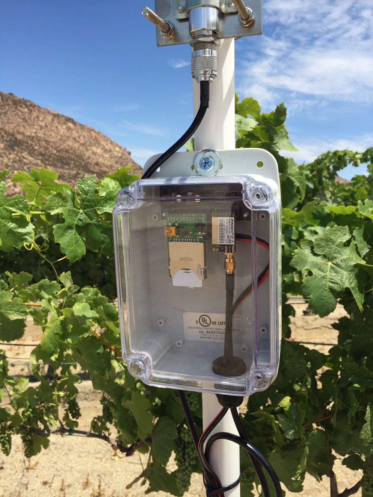
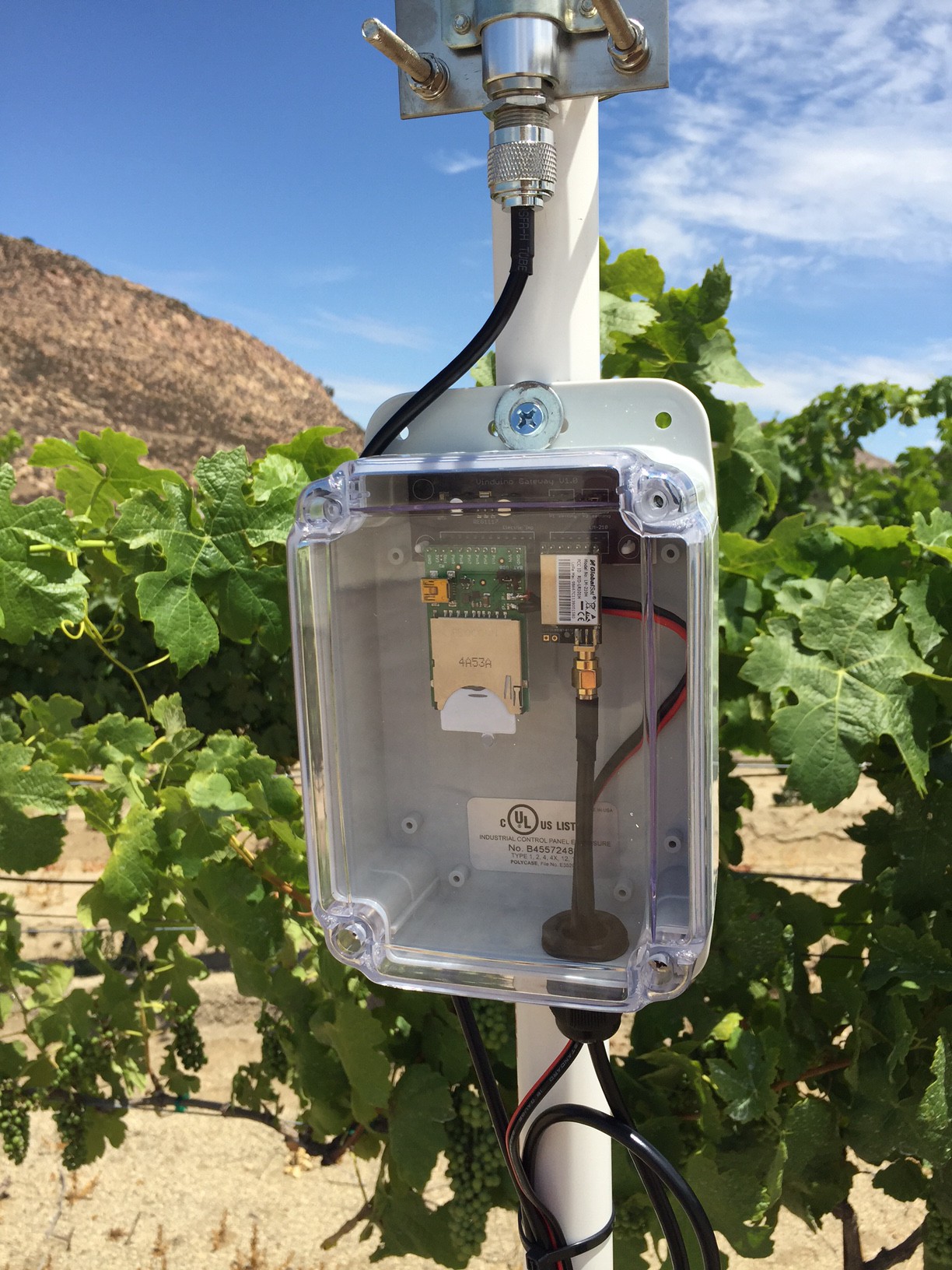
Below is a picture of the Vinduino gateway, which relays data from the remote sensor stations on the LoRa network via WiFi to the Internet.
-
LoRa network module review
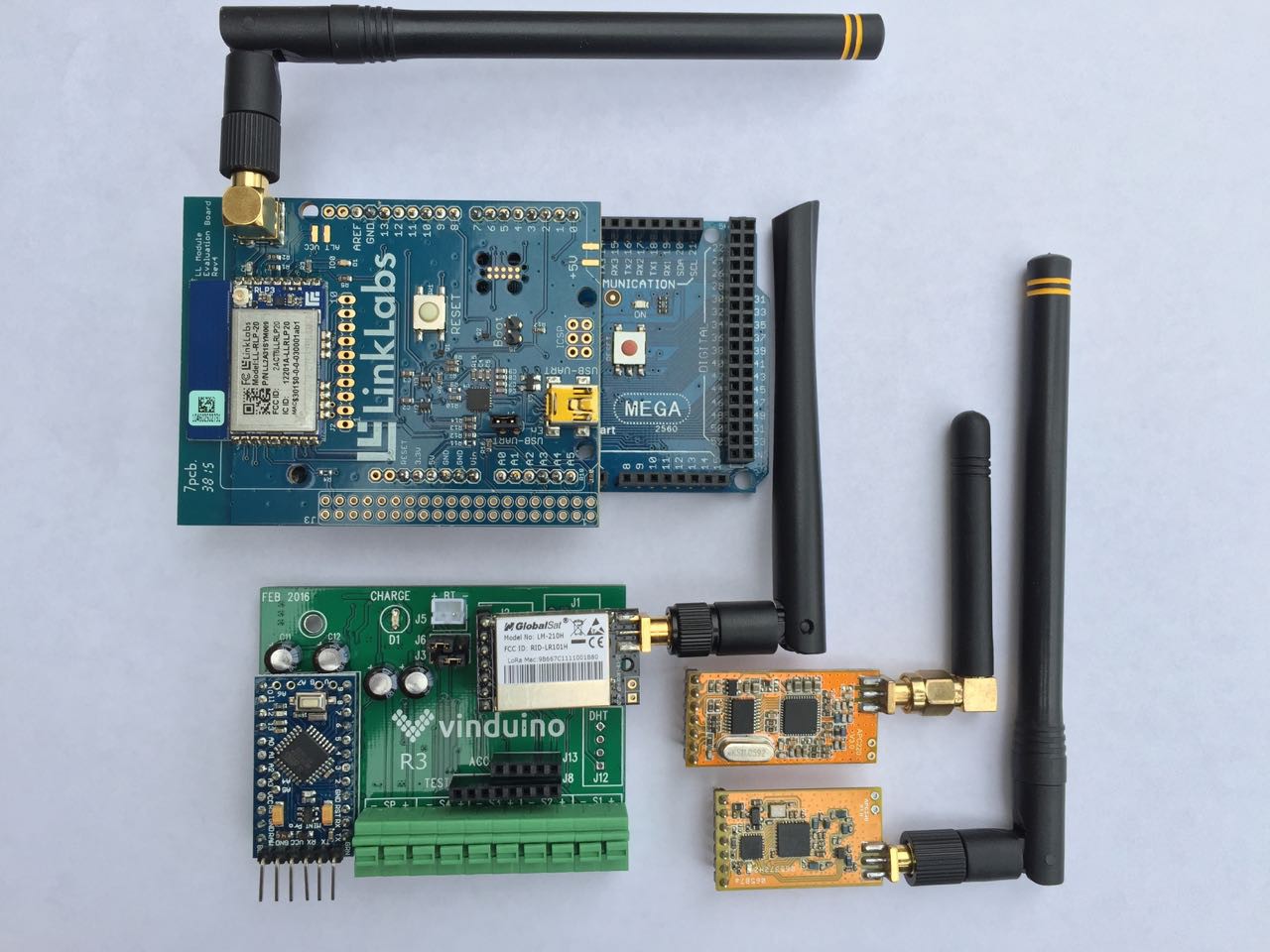
06/05/2016 at 23:37 • 1 commentIn this update, I cover experiences with 3 different modules, all using the same Semtech SX1276 LoRa chip, designed for use in the 915 MHz license-free band in the US and 868 MHz in Europe. The first generation of Vinduino remote sensor stations used ESP8266 WiFi modules. They work great in and around the house, but lack the range for agricultural work.
With the LoRa modules evaluated, a range of up to a few miles is easily achieved with standard "rubberduck" antennas and line of sight. When using antennas that provide gain, you can get some serious distance. When testing with a 9 dB gain directional antenna on the balcony, and a loRa module with a standard antenna mounted on my car roof, I got a 6 mile range. A Finnish team from the university of Oulu reported 30 km (20 mi) range over water and 15 km over land using standard antennas.
My requirements for the Vinduino telemetry were: long range (>1 mile), easy to work with, FCC approved, license free frequency use, robust communications, and low cost.
Model Arduino compatible Frequency FCC approved Estim price APC220 yes 430 MHz No $14 APC340 yes 915 MHz No $27 LinkLabs
LL-RLP-20Arduino Mega 915 MHz Yes $44 Globalsat
LM-210yes 915 MHz Yes $25 Before introduction of the ESP8266, the APC220 was the module of choice for making wireless Arduino projects.
They work as transparent wireless UARTS, serial data in = serial data out. Very easy to work with. Range of this module is just block away, and not being FCC aproved made me look at a new arrival from the same company, Appcon in Shenzen, APC340. I ordered some samples and they worked great, the only thing missing was FCC approval.
Next module evaluated was a new module from LinkLabs, also using the same Semtech LoRa chip as the APC340, and FCC approved. There is even an Arduino sketch available, but unfortunately this only works for their Symphony LoRa WAN architecture. You can write to the registers for making it work as a wireless UART, but that mode is not supported and not FCC approved.
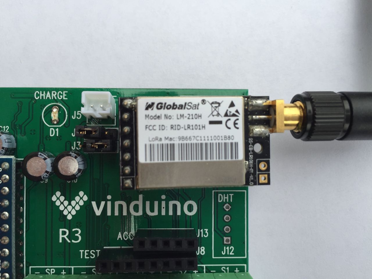
Finally, I met with the folks of Globalsat at CES. They were introducing a new range of products for LoRa and LoRa WAN, and all their products have FCC approval.
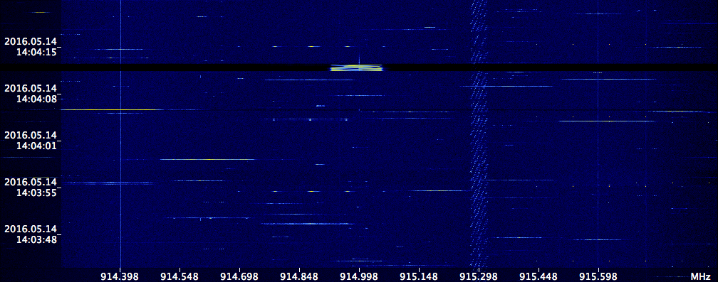
I have been using their LM-210 module for a few months now and had good results with field testing. The 915 MHz band has many users, all doing some kind of spread spectrum modulation. For use in Europe, I was able to program the module to work at 868 MHz, at 14 dBm output level. The LM-210 uses spread spectrum modulation as well, distributing the signal over 125kHz. Viewing with a SDR radio, the radio signal looks like this:
The radio link includes forward error correction, and in most situations that works well enough. In situations where the signal strength is not enough to maintain the connection, errors can slip through. To maintain data integrity in challenging environments it's therefore better to have a CRC check in the software.
The LM-210 connects with a 7-pin header. The I/O voltage should be 3.3V, the supply voltage can be up to 6V, but to be sure, I operate Arduino and LoRa module at 3.3V.
Working with the modules is straightforward, data in = data out. The interface bitrate comes as default 9600 bps. The RF signal rate can be programmed between 0.81 and 18.23 Kbps. RF output power is 20 dBm (100mW), and can be reduced in 7 steps of 2 dB.
The module has two mode selection pins, that are pretty interesting to play with.
Mode 1, Pin 1=0 and Pin2=0: the channel is opened and the module is active. This is also the mode with highest power consumption: 13 mA typical for receive and 120 mA for transmit.Mode 2, P1=0 and Pin2=1: difference with mode 1 is that every transmission now starts with a preamble needed to wake up a receiver in wake-up mode (see mode 3), and RSSI data is added.
Mode 3, P1=1 and P2=0: Power saving mode. The receiver is in sleep mode and wakes up at a set interval. If a transmission preamble is detected, receiving starts until the transmission is ended.
Mode 4, P1=1 and P2=1, Setup mode. Changing frequency, output power etc is done by sending hexadecimal string in this mode. This is also the setting that takes the least power (2.2uA) as RF and UART as closed. For Vinduino I have the Arduino board in the remote stations toggle between Mode 4 (sleeping) and Mode 1 (transmission). The Vinduino gateway is always on, actively receiving, and remains in Mode 1.
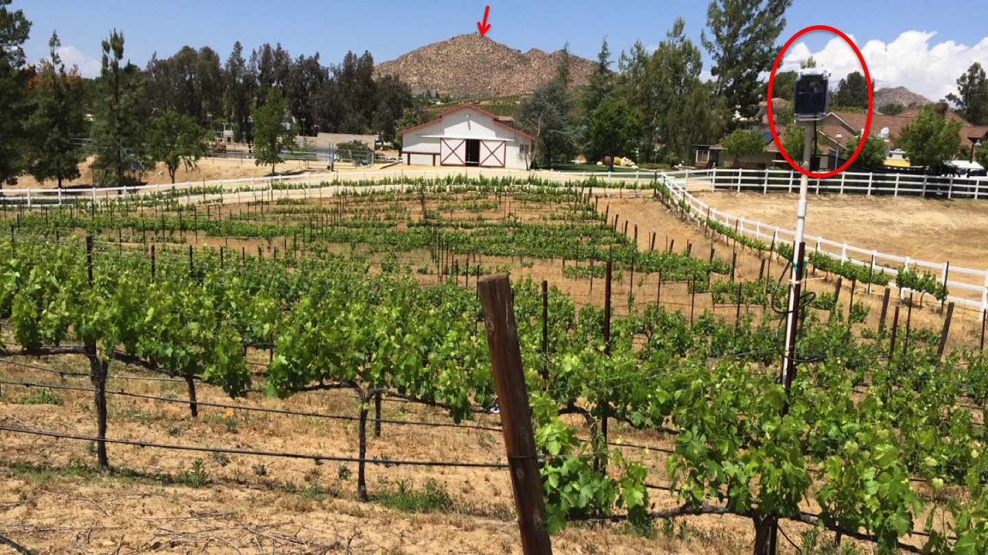
The 915 MHz band has some interesting properties. Radio signals bounce off objects, the Navy used the 915 MHz band for RADAR detection of low flying objects over water.
In the vineyard shown below, there was no direct line-of-sight between the sensor station (circled) and the LoRa gateway which is behind a hill. Nevertheless, a reliable communication path was established by bouncing the radio signal off a nearby mountain (arrow).
Thus far we have successfully installed Vinduino sensor stations at 7 vineyards in the Temecula wine area, and the choice for using LoRa technology for our telemetry has not been a disappointment.
The range of LoRa makes it also an ideal technology for community IoT networks. We think one well located LoRa gateway can support hundreds of IoT stations in a few miles radius, and forward sensor data to -for example- ThingSpeak. Adding a fiberglass omni-directional antenna brings out the best of the module when used in a gateway configuration.
An opportunity for citizen network providers?The Globalsat LM-210 is available from Embedded Works for $19.99 excl. antenna. For the record: I have no commercial ties with this company.
-
Using a Solder Paste Stencil
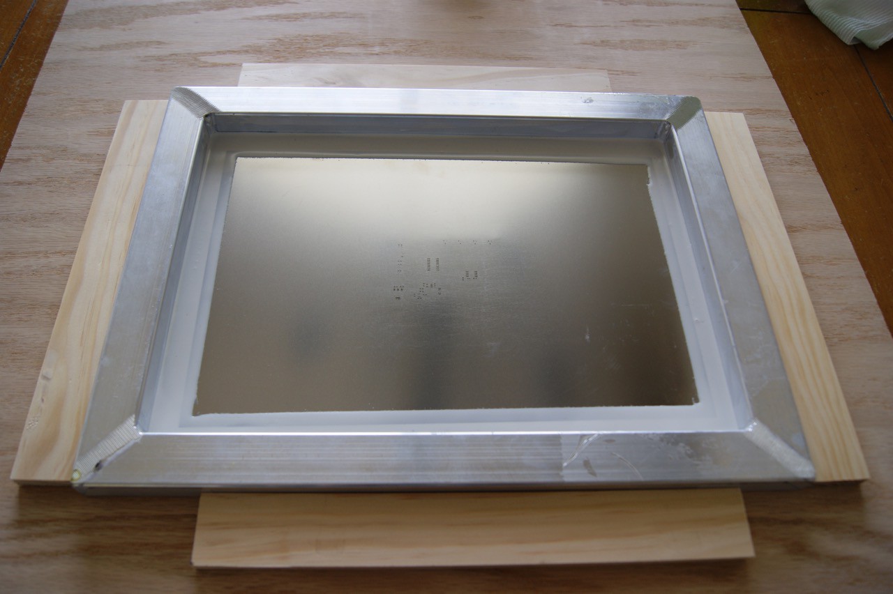
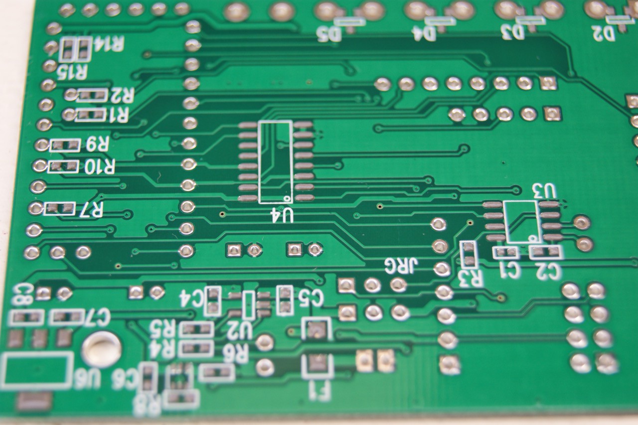
03/20/2016 at 17:37 • 3 commentsFor upcoming trial installations, I need 25 Vinduino printed circuit boards. Not a sufficient enough quantity for cost effective outsourcing of assembly. The new version of the Vinduino board has a good number of SMD components, and after building the first board with solder paste, toothpick, and hot air tool, I knew I had to find a faster way. So when I ordered PCBs @ Elecrow.com, I clicked on the option for having a 30 x 40 cm framed metal stencil. Added cost for the metal stencil is $18 + shipping, a bargain!
The PCBs and stencil arrived one week later, and I was pleased with the quality of the stencil and the frame. Now I was in the market for a stencil printer. A unit with good reviews will cost you over $500 + $200 shipping (weighs 17 kilo) from China. The $150 units on Ebay get mixed reviews, so was not sure if I wanted to squander HackaDay prize money on that.
I ended up not buying a stencil printer (for now), but instead made a $20 wooden positioning frame that works accurately, and gives repeatable results.
To fix the position of the PCB, I used iron-on edge tape. Then I moved the frame until it was perfectly aligned with the PCB pads. The frame position is fixed with pieces of wood glued to the base board.
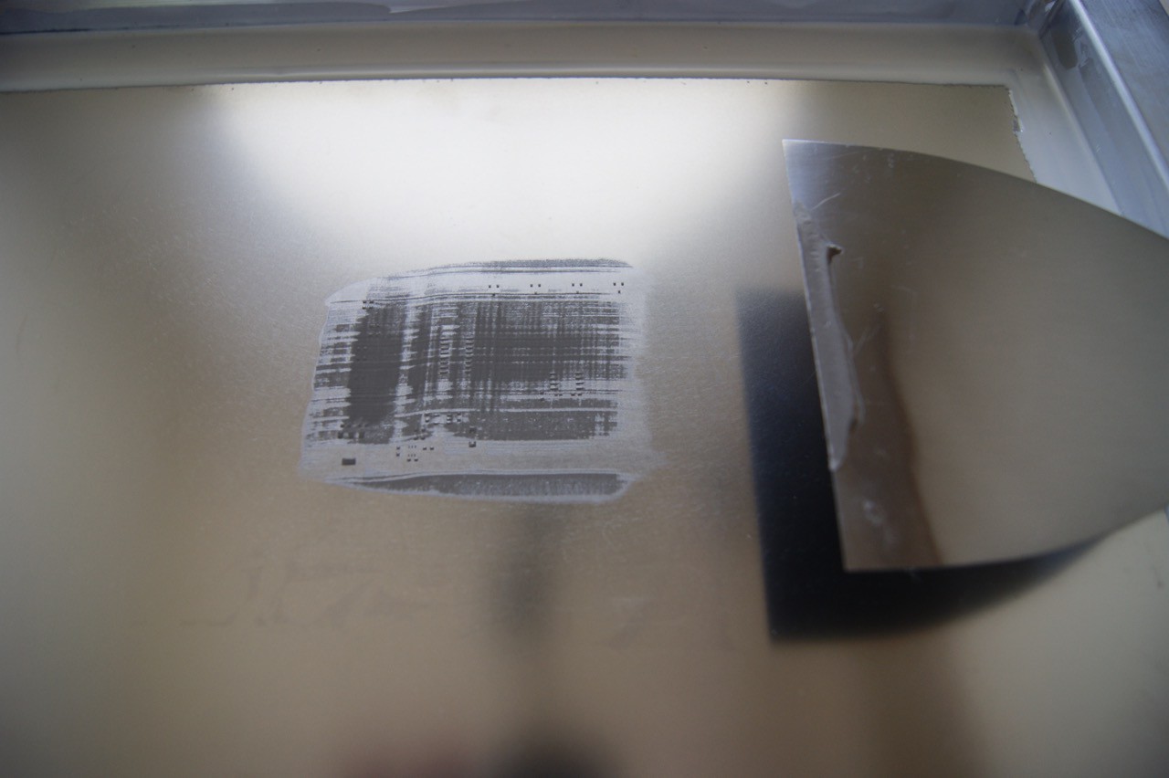
For first tests, I used low temperature lead free solder paste, and a putty knife to apply the solder paste. One single pass should be enough.
The method gets me good solder paste dosage, and accurate alignment.
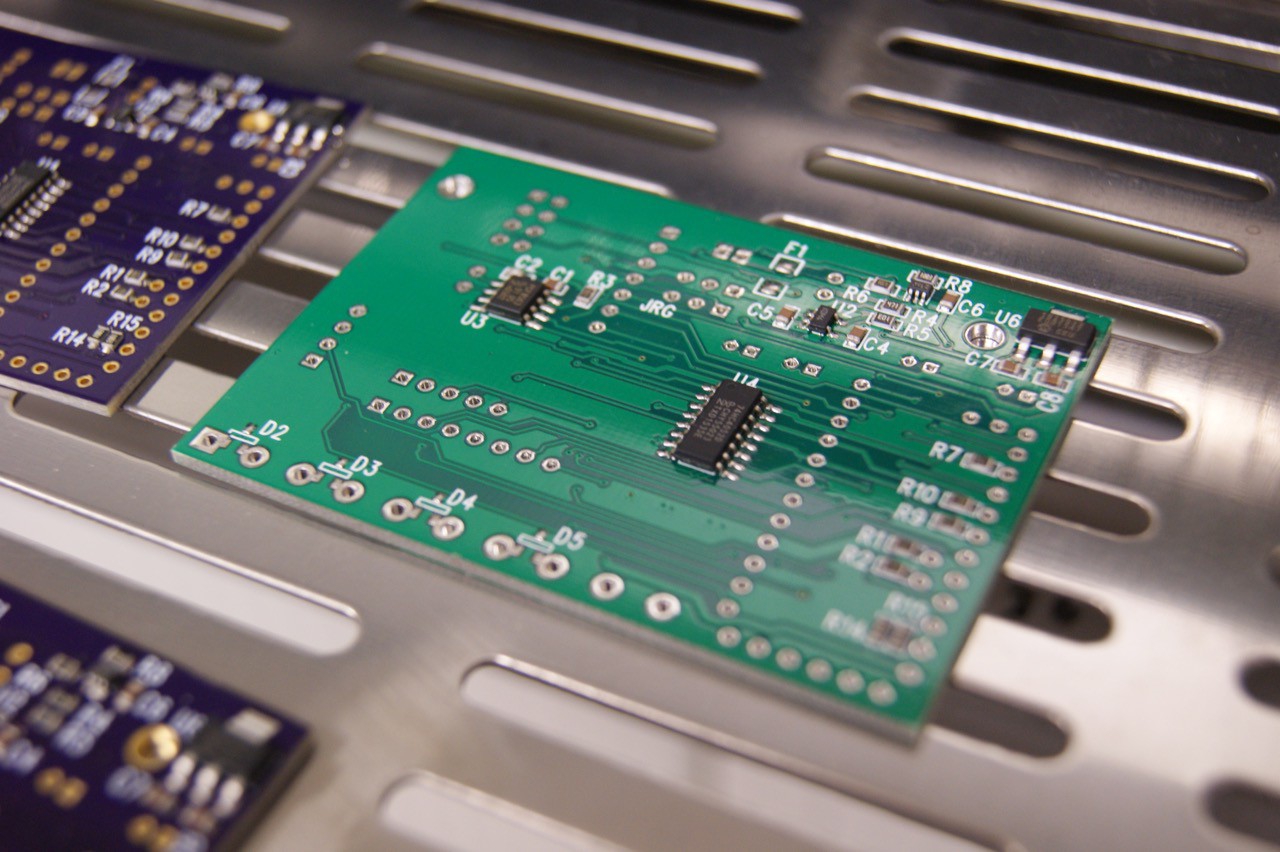
Fresh from the T962A oven, all solder pads passed visual inspection. Looks much cleaner than the manually applied solder paste build I did on the very first board.
No rework was needed.
After assembly of the top side through-hole components, all boards work as expected. -
More green coming to vineyards soon
03/13/2016 at 16:07 • 0 commentsIt's March, and we have budbreak in our vineyard. Spring is in the air, smell of jasmin everywhere.
This is a great time to be in the vineyard.
We were hopeful that this Winter would see a lot of rain, but so far El Nino did not bring the much needed relief from a multi-year drought.
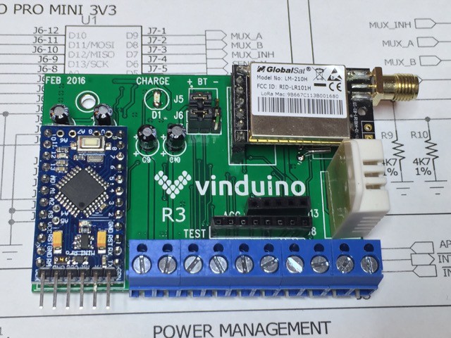
There is more fresh green coming to vineyards this year. In preparation of the new season, and with help of our Hackaday friends and Analog.io, the Vinduino project has been developing a new generation of the Vinduino soil moisture monitor.
The new Vinduino R3 (Remote, 3rd generation) has the following features:- 4 inputs for (gypsum) soil moisture sensors
- built in (solar) battery charger
- support for 6 mile long range (Globalsat LM-210, LoRa) radio module or ESP8266 WiFi
- clock module for precise irrigation timing
- on board temperature and relative humidity sensor
- accessories port for optional irrigation valve control and extra sensor
- power management circuits, resulting in lower power consumption
- open source (of course)
For LoRa operation, we are developing a low cost gateway capable of handling 300 end nodes within a 6-mile radius.
More on that later.
Vineyard trial installations start next month. We'll keep you updated on our progress.
-
Planning ahead to replace gypsum sensors
03/06/2016 at 19:34 • 1 commentGypsum sensors slowly dissolve in water, and while doing so provide a salinity level around the electrodes that makes the sensor less sensitive to soil salinity.
While their active life may be a few years, gypsum sensors will not last forever. So while installing, it's good to plan ahead for their replacement.
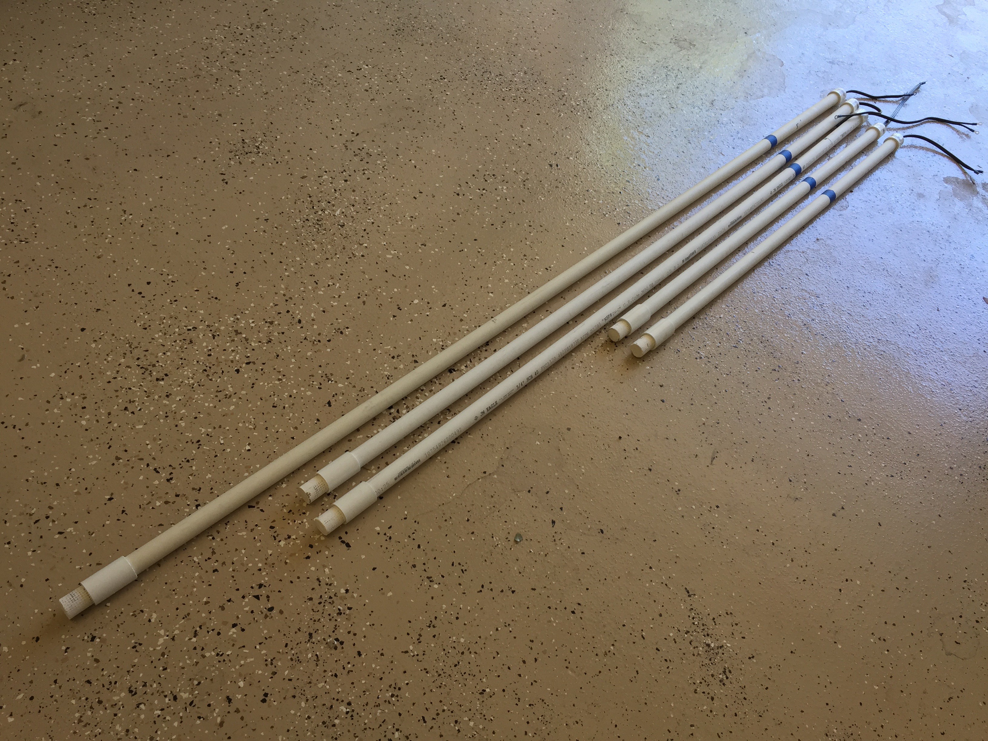
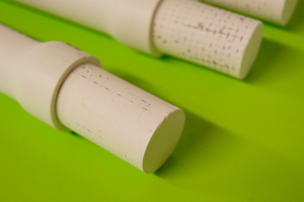
The way I installed my sensors before is show below, using pipe couplers at the end of the required length PVC pice.
In this case, I installed sensors at 2 feet, 4 feet, and 5 feet depth.Pulling them out improved an impossible task, as the couplers provide too much friction in the soil. The only way to replace is dig them out.
A solution is to forego using couplers, and integrate the sensors with the pipe.
The PVC pipe can be stretched to a wider diameter after heating with a heat gun. I found a temperature of 150-175C, makes the PVC flexible enough without burning or releasing fumes. A hot air rework stations works fine for this.
After stretching, let it cool at it's wider diameter and place the sensors inside. Then heat the pipe again. The PVC pipe will shrink around the sensor, forming a tight fit after cooling. Now removing a sensor pipe is "only" a matter of applying sufficient force. -
Vinduino Low Power Wide Area Network
02/21/2016 at 21:47 • 0 commentsWe are hard at work to get first vineyard trial installations done by early April.
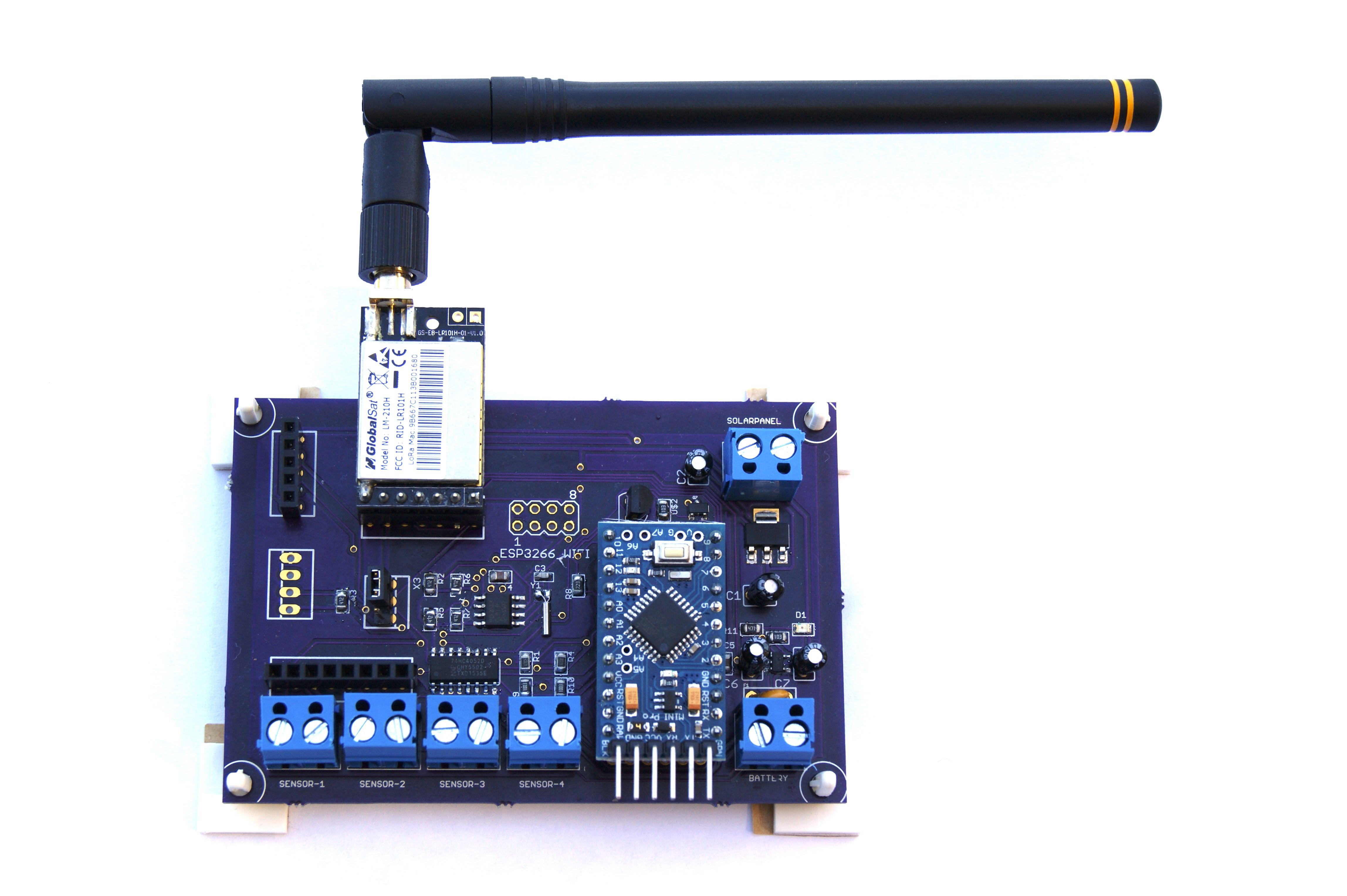
Too busy for frequent update logs, but here's a snapshot of what's going on.There will be an updated design for the Vinduino remote node. See picture below.
Updates include:
- 4 sensor inputs (previously 3)
- integrated RTC
- integrated battery charger and solar panel support
- lower power design
- support for Globaltech LM-210 LoRa radio modem (licence free 915 MHz band)
- lower cost components

As I am still working on finalizing the schematics and PCB, there is no update on Github yet.
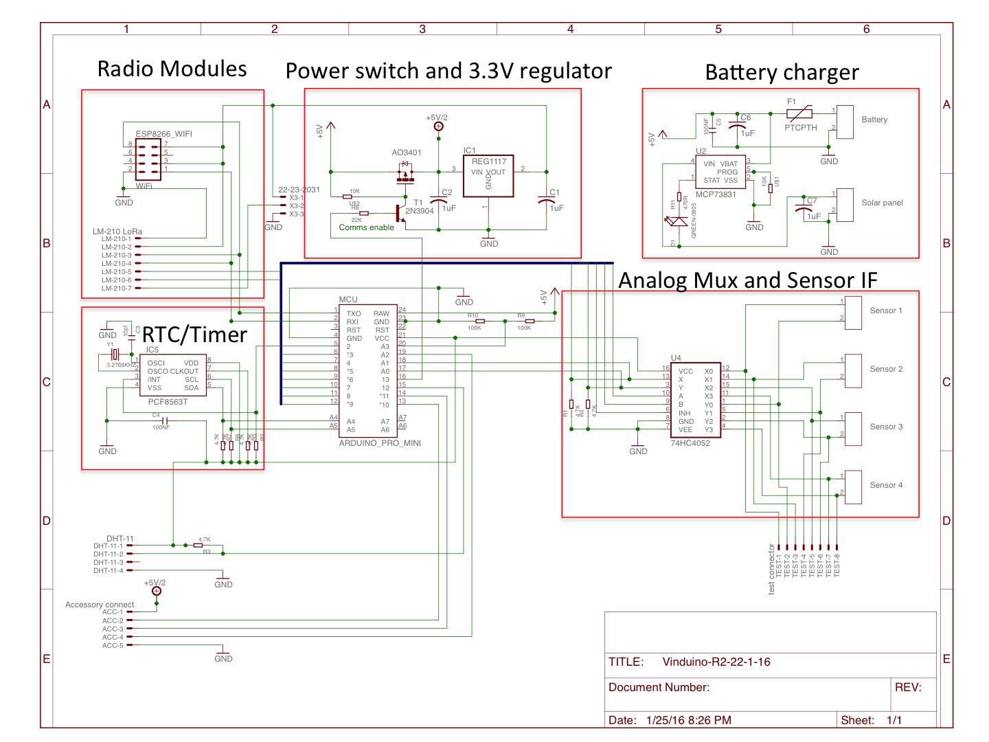
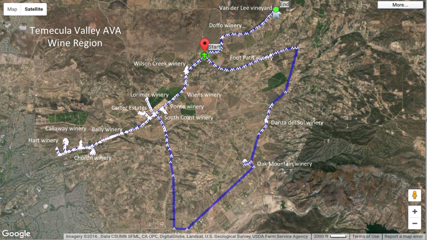
Below schematic is not finalized, but provided here for a high level impression.Range experiments using the FCC approved GlobalTech modules show a range of at least 6 miles. I had one unit set up on the balcony of our house in Temecula, and the other unit was connected to a GPS receiver on the roof of my car, reporting GPS coordinates and RSSI (radio signal strength) every 10 seconds. The data was imported in Google maps, showing the coverage. See picture below.
Basically, for all the wineries located around the main winery road, Rancho California road, there is good coverage. There is another wine trail road, De Portola, that does not have full line-of-sight coverage from my vineyard location. Based this data, we assume that the whole wine region can be covered with a star topology using only 2-3 central hubs. Assuming hourly transmissions per node, we can support up to 300 remote nodes per hub.
In collaboration with Luke Beno's Analog.IO project we are step-by-step resolving the issues of managing a network of this scale.
Vinduino, a wine grower's water saving project
Monitoring soil moisture at different depths to determine when to irrigate, and - more importantly - how much water is needed. Save 25%!
 Reinier van der Lee